
 ?Mathematical formulae have been encoded as MathML and are displayed in this HTML version using MathJax in order to improve their display. Uncheck the box to turn MathJax off. This feature requires Javascript. Click on a formula to zoom.
Abstract
The molten salt reactor is characterized by its use of the fluid-fuel, which serves both as a fuel and as a coolant simultaneously. The position of delayed neutron precursors continuously changes both in the core and in the external loop due to the fuel circulation, and the fission products are extracted by an online fuel reprocessing unit, which all lead to the modeling methods for the conventional reactors using solid fuel not applicable. This study establishes suitable calculation models for the neutronics analysis of the molten salt reactor and develops a new code named MOREL based on the three-dimensional diffusion steady and transient calculations. Some numerical tests are chosen to verify the code and the numerical results indicate that MOREL can be used for the analysis of the molten salt reactor. After verification, it is applied to analyze the characteristics of a typical molten salt reactor, including the steady characteristics, the influence of fuel circulation on the kinetic behaviors. Besides, the influence of online fuel reprocessing simulation is also examined. The results show that inherent safety is the character of the molten salt reactor from the aspect of reactivity feedback and the fuel circulation has great influence on the kinetic characteristics of molten salt reactor.
1. Introduction
The molten salt reactor (MSR), one of the six candidates for the Generation IV reactor types, was first developed in the Oak Ridge National Laboratory (ORNL) in the late 1940s and has been studied in the past 60 years with intermittent attention [Citation1]. The remarkable advantages in terms of safety, economics and nuclear proliferation resistance encouraged many researchers to put renewed efforts in the study of such reactor recently [Citation2].
The MSR concept was initially proposed by ORNL in the projects of aircraft reactor experiment, which was constructed in 1954 and become the first MSR in the world. Afterwards, the molten salt reactor experiment (MSRE) was constructed to research vessel complexity and limited graphite lifetime. The favorable experience gained from the MSRE test reactor led to the concept design of a reference breeder design with a thermal spectrum and thorium fuel cycle, the 1000 MWe molten salt breeder reactor [Citation1]. In Japan, the concept of a small molten salt reactor (SMSR) was proposed to utilize the thorium and plutonium from light water reactors [Citation3]. In Russia, the concept of the molten salt advanced reactor transmuter (MOSART) was proposed to reduce long-lived waste toxicity and produce electricity simultaneously [Citation4]. In the close cooperation with MOSART project, the MSR technology has been evaluated in the frame of EU Program MOST [Citation5]. Several national or international MSR concepts were conceived and new research programs were launched. The performances and design parameters of MSR concepts have been extensively revisited in Europe in the EURATOM 6th and 7th Framework Programs (assessment of liquid salts for innovative applications [ALISIA] and evaluation and viability of liquid fuel fast reactor system [EVOL] projects) [Citation6]. These studies led to the design of fast spectrum concepts: fast neutron spectrum molten salt reactors (MSFR), which have a good breeding capability when using the thorium fuel cycle but high power densities would be required to avoid excessive fissile inventories [Citation7]. From 2011, the Shanghai Institute of Applied Physics started the “Thorium Molten Salt Reactor Nuclear Energy System” project in China and aimed to develop the TMSR to realize the effective utilization of thorium and hydrogen production by nuclear energy within 20–30 years [Citation8].
The MSR has many characteristics such as using fluid-fuel, online fuel reprocessing, etc. The fuels like UF4 or ThF4 are dissolved in the fluoride salt which serves as fuel and coolant simultaneously. The fission products are released into the molten salt and flow with the salt through the core and primary loops, and then extracted by an online fuel reprocessing unit. In the process, the delayed neutron precursors (DNPs) are carried to change the positions and some of them decay in the external loops. It makes the behavior of delayed neutrons significantly different from the ones in traditional reactor using solid fuels. To investigate the flow effect of fluid-fuels, new methods should be proposed for the MSRs.
Efforts on the investigations of transient behavior and fuel cycle performance of the MSR had been carried out by many researchers based on different hypotheses and simplifications. Lapenta et al. analyzed the neutronics of MSR using the point kinetic model [Citation9], while Dulla et al. adopted the quasi-static method in two-dimensional (2D) cylindrical geometry to simulate some transient processes like pump coast down and overcooled inlet temperature [Citation10,11]. Kophazi et al. modified the MCNP4C (A Monte Carlo N-Particle Transport Code, Version 4C) code to calculate the loss of DNPs considering the transport of DNPs [Citation12]. Wang et al. focused on the simulation of fluid dynamic and the optimization of MOSART design in the steady-state condition by using the extension models based on the SIMMER-III code which employed 2D R–Z geometry [Citation13]. Yamamoto et al. performed the steady-state and transient analyses on the SMSR by coupling the neutron diffusion equation with the heat transfer equation in fuel salt and graphite [Citation14,15]. Křepel et al. developed the DYN1D-MSR and DYN3D-MSR codes for the safety analysis on graphite-moderated channel-type MSR, in which the one-dimensional (1D) flow model was adopted in the three-dimensional (3D) code [Citation16,17]. The DYN1D-MSR and DYN3D-MSR codes adopted nodal expand method in the hexagonal geometry. Zhang et al. performed the safety analysis on MOSART by employing simplified heat transfer and neutronic models [Citation18,19]. Lecarpentier develop a safety code employing 1D thermal-hydraulic and 3D neutron diffusion equation to study the AMSTER system [Citation20]. In respect of fuel cycle and online fuel reprocessing simulation, ORNL developed ROD code, based on multi-group and 1D or synthetic 2D diffusion theory, to perform a fuel cycle analysis, including costs either at equilibrium, for continuous processing, or time-dependent for batch or continuous processing [Citation21]. Manuele Aufiero extended SERPENT-2 Monte Carlo code to study MSR fuel burnup (BU) [Citation22]. S. Delpech coupled the MCNP and REM (a home-made materials evolution code) depletion codes to study the breeding and transmutation performance of MSFR system [Citation23]. Despite the Monte Carlo transport code has advantages in modeling complex geometry and performing the whole core heterogeneous calculation, it is too costly to simulate the fuel cycle and be applied in optimizing the design of the core.
It should be noted that most previous studies were carried on by using various hypotheses or simplified models. In order to provide a deeper insight into the steady-state and transient characteristics of an MSR, this study focuses on the suitable calculation models and developed a new code named MOREL, which is a comprehensive but special code for the neutronics calculation of MSR. MOREL is based on the 3D diffusion calculation and the triangular prism nodes, which can be applied for different geometry. It can be easily used for different MSR designs and different aspects including the steady-state evaluation, the depletion analysis or neutron kinetics simulation, etc.
The calculation models are introduced in Section 2. The verification of the code is presented in Section 3 and the application of the code for MSR analysis is shown in Section 4. Finally, some conclusions are summarized.
2. Methods and code development
A new code, named MOREL, for the neutronics studies on MSR is newly developed, consisting of the functions for steady and transient analysis and the potential for fuel cycle performance evaluation. The calculation scheme of MOREL is divided into two steps: the generation of few-group constants and kinetics parameters, and then the 3D in-core neutron diffusion calculation, depletion calculation or space-dependent kinetic calculation. The few-group constants and kinetics parameters are generated by the lattice code HELIOS in 2D assembly calculation and the 3D in-core neutron diffusion calculation is performed by the code TABFEN, which is based on the analytic basis functions expansion nodal method for arbitrary triangular-z node and suitable for different geometries used in current MSR designs. In the kinetics calculation, also the 3D model considering the axial flow effects of DNPs is established, using the method of characteristics to solve the DNP equations in the primary loop considering part of DNP decay on the external loop and reenter the core. In the depletion calculation, all nuclides considered in the burnup chains are tracked to simulate the online fuel reprocessing process and prepared for the fuel cycle analysis. The transmutation trajectory analysis method (TTA) is employed in this calculation.
2.1. Few group constants and kinetics parameters
The few-group constants of assemblies include the homogenized microscopic cross sections of nuclides in the burnup chains, homogenized macroscopic absorption cross section of the residual nuclides in the fuel assembly and homogenized macroscopic cross sections of other material. The anisotropic scattering is considered using transport correction method. The interpolation tables for the few-group constants are established by 2D assembly calculations considering assembly parameters such as fuel temperature (TF), graphite temperature (TG) and burnup, which are used in the nuclides depletion and online fuel reprocessing simulation.
The decay constants and fractions of DNPs for family i are defined as follows:
(1)
(1)
(2)
(2)
In which the subscript m stands for the nuclide type and Nm is the nuclear density of m nuclide.
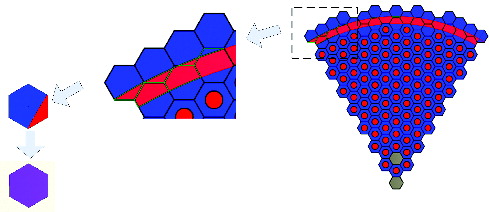
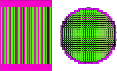
The 2D infinite assembly calculations using HELIOS are executed based on the multi-group cross sections from ENDF/B-VI [Citation24]. In HELIOS, the sub-group method is used to perform the resonance calculation and the transport method involved is the current-coupling collision probability method. The few-group cross sections are generated based on different models; for instance, the single assembly model is used for the calculation of traditional fuels while different cell or super-cell models are used for the complex structures. For example, illustrates one of the homogenization models. It is used for a kind of MSR using circular fuel channels around the active core. All the nuclides in this model will be mixed based on the volume weight and then the mixed assembly will be homogenized as the traditional fuel assembly.
Figure 1. The homogenized process of circular fuel channels.
2.2. 3D core calculation method
In order to be applied to the complex geometry in different MSR designs, the 3D neutron diffusion calculation based on arbitrary triangle-z node is adopted. The MOREL code employs the 3D neutron diffusion solver TABFEN. It is a home-developed nodal diffusion code based on the analytic basis functions expansion method using triangle-z node [Citation25]. The triangle nodes are generated by ANSYS-14.0. The few group constants are interpolated according to the current core parameters, i.e. TF, TG and BU.
2.3. Neutron kinetic calculation method
The 3D neutron diffusion equation and 1D balance equation of DNP considering fuel circulation are established in this research. Due to those precursors flow along with the fuel circulation, both in the reactor core and in the external loop, part of DNP decay on the external loop and reenter the core, which makes the kinetics of MSR different from that of conventional reactors using solid fuel. As is shown in the previous research, the fuel circulation brings little effects on the neutron flux for MSR [Citation26]. Therefore, those effects are represented by an additional convective term only in the balance equation of DNP and considered both in the core and the loop.
The space-depended neutron kinetics equation consists of G groups of neutron diffusion equation and I families of DNP balance equations, which can be derived based on the conservation law in a control volume. They are described as follows:
(3)
(3)
(4)
(4)
Standard notations are used and U is the vector of fuel velocity. Only the axial fuel flow is considered in the present research.
The implicit finite difference method is applied to discrete the time-derivative term in Equation (3) and the TABFEN code is employed in every discrete time step as
(5)
(5) where
; the elements in matrix
can be represented as following:
(6)
(6) In which
and
The element in vector is represented as
(7)
(7) Standard notations are used. The item containing Ci(r, tn) in Seffg(r, tn) couples the neutron equations and the DNP balance equations.
in Equation (5) can be got by TABFEN solver. The solution of the diffusion equation (5) depends on the eigenvalues λm and corresponding eigenvetors
of the matrix
. For simplicity, we present out derivation here only for the case in which the eigenvalues are real. In fact, the eigenvalues are real for two-group problem and this kinetic method can be applied to multi-group. The solution
of Equation (5) consists of a general solution and a particular solution [Citation27]:
(8)
(8)
(9)
(9) where
and s(r) is the particular solution of the inhomogeneous equation (5).
When the flux at tn − 1 is known, the flux is assumed as a form of exponential function with the corresponding time in every node between tn − 1 and tn:
(10)
(10) where ϕg(z, t) is Equation (8) which is integrated in the X–Y direction in every node, tI is the beginning of the calculated time step; here it is tn − 1. Ω is the constant about flux changing along with time and determined by the nodal flux between two times steps.
The source item in the DNP balance equation is marked as Q(z, t). Equation (4) has the same form for different families of DNPs in each node with only axial direction consideration. Consequently, the index i will be neglected in the following equation:
(11)
(11)
The method of characteristics is used to solve Equation (11) through the core and external loop in every time step [Citation16].
As the velocity of fuel in each node is assumed to be constant in every time step, Q(z, t) can be written as Q(z) by transformation:
(12)
(12)
(13)
(13) where t0 is the node entering time, z0 is the height of node bottom, ϵ is the position at initial time, Rml and s(z) are values after the general solution and particular solution being integrated along the X–Y direction, respectively.
The solution of Equation (11) can be obtained by using total differential form of C(z, t):
(14)
(14) where v is the velocity of fuel.
The fictitious fluid particle of present node will be tracked on its upstream through one or more nodes during one time step.
From Equations (12) and (14), the DNP outgoing concentration can be written as
(15)
(15) where N1, NA, m and NB, m are the constants after the integration of Equation (12).
In the external loop, there only exists a decay for DNP as follows:
(16)
(16) The reactor core is treated as multichannel model for DNP transport along with fuel circulation. Because the assembly is homogenized at the first step and then divided into several triangle-z nodes in core calculation, all the triangle-z node which belong to the same channel should keep fuel velocity and fuel density the same in each layer. In these channels of active core, the same mass flow rate is considered. Fuel mixing takes place in the upper plenum. Thermal hydraulics is not considered in this research, all the velocity and density of fuel used in the Section 3.2 is referred from MSRE operation reports.
2.4. The loss of effective delayed neutron fraction
Part of the DNPs decay outside the reactor core due to the circulation of fuel. It reduces the effective delayed neutron fraction (βeff). Consequently, the effective delayed neutron fraction for family i is defined as Equation (17) by introducing the ratio between total importance of delayed emissions from family i and total importance of all fission neutrons [Citation28]:
(17)
(17)
Standard notations are used, ϕ*g(r) is the adjoint flux without considering the reduction of delayed neutron worth due to the change of position.
The loss of effective delayed neutron fraction βloss is defined as
(18)
(18) where βi, staticeff and βi, fuel floweff are the effective delayed neutron fraction of family i when the fuel velocity is neglected and considered, respectively.
2.5. Boundary conditions
Two boundary conditions are considered in the calculations as:
Inlet boundary: The vacuum boundary condition is employed for neutron flux at the inlet, since the neutron extrapolation distance is negligible compared to the dimension of the whole core. The DNPs which do not decay in the external loop and return to the core are taken into account.
(19)
Outlet boundary: The vacuum boundary condition is also employed for neutron flux at the outlet of the channel. The flow of DNP keeps constant between core outlet and external loop inlet.
2.6. Nuclides depletion
Online fuel reprocessing makes the variation of fuel composition complex, therefore more fine nuclides depletion models need to be developed. In the depletion calculation module of MOREL, every fuel assembly is divided into several segments along axis direction, which are also the nodes used in the core diffusion calculation, and every segment will be regarded as an independent burnup region, in which the depletion equation system is solved with TTA algorithm based on the fine depletion chains to obtain the mass change of individual actinides during the fuel cycle [Citation29].
The typical scheme of MSR online fuel reprocessing is shown in . For the purpose of removing most of the fission products, an online reprocessing is required. Thus, periodically, batches of salt have to be removed and then sent back to the core to be consumed. Homogeneous mixing of all nuclides is employed after the batches of fuel reprocessing. The consumption ratio of fissile nuclide represents the level of burnup, which isused for microscopic cross section interpolation at the next diffusion calculation and micro-burnup calculation. As the few-group homogenized microscopic cross sections of nuclides of the fine depletion chains are used in the depletion calculation, the macroscopic cross section of assembly can be obtained from the nuclides density which can be changed by the scheme of refueling and then whole core depletion calculation will be performed. The scheme of refuel is not designed in this research but some nuclides density is directly changed to simulate online reprocessing like Section 4.2.
Figure 2. The flow chart of fuel reprocessing process.
To consider the flux amplitude variation in the certain burnup step, a sub-step method is performed. Each burnup step is divided into some sub-steps, in which the flux amplitude is supposed to be constant. At the beginning of every sub-step calculation, the flux amplitude is renormalized based on the total thermal power.
3. Code verification
In this section, the new code is verified with two group constants. The TMSR core depletion problem was chosen to verify the depletion module, in which the reference results are calculated by a code package named MCNT/ORIGEN2 which couples the Monte Carlo transport code and the depletion code [Citation30]. For the neutron kinetic module verification, the data from MSRE experiments are referred, which contains the data of effective loss of DNP in steady state and two-transient state including protected fuel pump startup and coast down.
3.1. Verification of steady core calculation
The TMSR project was proposed by Shanghai Institute of Applied Physics (SINAP) in China considering the remarkable advantages of MSRs. The preliminary design of TMSR is employed in this paper to verify the MOREL code. The reference results are calculated by a Monte Carlo transport code coupled with a depletion code. The simplified reactor core configuration is shown in (left) and the parameters are list in .
Table 1. Parameters of TMSR.
Figure 3. TMSR geometry and core configure (left) and geometry of TMSR pin cell (right).
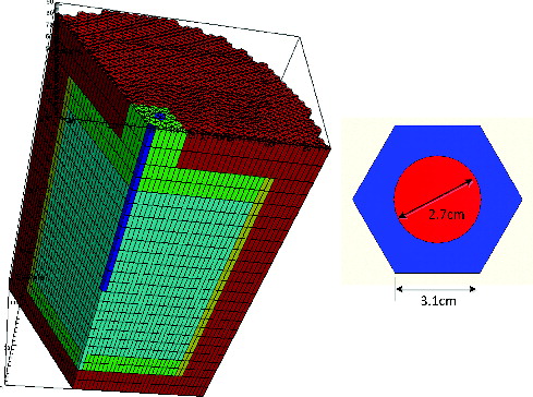
The TMSR is a 10 MWth thermal reactor moderated by graphite. The fuel circulates through the core filled with hexagonal graphite tube, which is shown in (right). There is a circular passage between arrays of hexagonal graphite tube and the graphite reflector. The inner and outer radius is 70 and 73 cm, respectively. The radius of whole core is 93 cm. The upper and lower plenums of 20-cm height are filled with fluid-fuel to cover the top and bottom of fuel tubes.
In the calculation, the reactor core is discretized into triangular prisms. It makes that some nodes overlap the circular fuel passage inevitably. Special treatments in the homogenization, as presented in the Section 2.1, are adopted in generating the few-group constants in those nodes based on the weight of nuclear density of fuel and graphite. The cross sections in different operating conditions are prepared by HELIOS, which are made into interpolating table of temperature and burnup.
displays the comparisons between the MOREL code and Monte Carlo code. It indicates that the depletion module in MOREL is capable of predicting the evolution of depletion. However, some differences still exist between two codes and the maximum error is 0.004 at 150 days of full power operation. The differences come from: (1) the burnup region division used in the Monte Carlo calculation that is slightly rougher than that used in MOREL; (2) the inherent differences between the Monte Carlo calculation and diffusion calculation; and (3) the different nuclear data library used in the calculations.
Figure 4. TMSR keff variation with burn-up.
3.2. Verification of dynamic calculation
The data from MSRE were employed to verify the code. The MSRE was an 8MWth reactor in which the molten fluoride salt at 922 K circulates through a core of graphite bars. Its operation with U-235 (93% enrichment) fuel salt began in June 1965 and U-233 was then added to the carrier salt. A calculation model is established based on the reports from ORNL. The data measured during the MSRE experiment are cited to verify the kinetic module especially the delayed neutron model in the MOREL code [Citation31].
As shown in , the calculation model is simplified with geometrical characteristics (radius R = 71.2 cm and height H = 200.7 cm), which is filled with the graphite lattice structure. The upper and lower plenums of 17.15-cm height with only fuel are placed at the top and bottom of reactor [Citation32]. The fuel velocity in the core is different from that in the plenum. The hydraulic parameters used in the calculation are referred directly from the literatures as following [Citation31]:
Figure 5. The approximated geometry of MSRE benchmark model.
The fuel velocity in the graphite lattice is 19.7 cm/s.
The fuel velocity in the upper and lower plenum is 5.1 cm/s.
The time of the fuel salt circulate the primary loop outside is 10 s.
3.2.1. The loss of DNP in steady state
The first case is preformed to calculate the loss of delayed neutron in the steady operation due to fuel circulation. The loss of delayed neutron is represented in terms of reactivity loss. The measured data in ORNL and calculated results from participants in MOST project serve as the reference results [Citation31,Citation33]. The reactivity loss of MSRE fueled by both U-233 and U-235 are all calculated. The comparisons are shown in and . FZK participates with two codes, SIMMER and SimADS: results are identified in the following with (a) and (b), respectively. MSRE and ORNL indicated in and are the experimental values of MSRE and the results of calculations performed at ORNL, respectively. The DNP data produced by HELIOS with ENDF/B-VI and offered by ORNL are indicated by (ENDF/B-VI) and (ORNL data), respectively.
Table 2. Loss in the delayed neutron precursor fractions (pcm) due to the fuel circulation for U-235 fuel compared to the reference [Citation31,32].
Table 3. Loss in the delayed neutron precursor fractions (pcm) due to the fuel circulation for U-233 fuel compared to the reference [Citation31,32].
and show the evaluated βloss of the six precursor families for the two types of fuel considered in the benchmark. It can be seen that the results calculated in this paper agree well with the results obtained by other codes, and most of the numerical results are larger than the experimental results. Some differences can be found by comparing the results obtained by different codes. Those differences may be caused by the different models used for evaluating the loss of importance of delayed neutrons and by different simplifications of the core geometry.
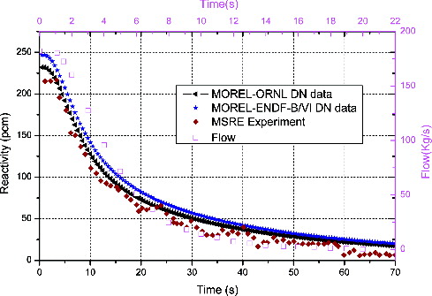
3.2.2. Fuel pump startup and coast-down
The other cases are performed to calculate the protected fuel pump startup and coast-down transients. The constant power is maintained during these two transient experiments. During the transient experiments, the central rod was withdrawn to maintain criticality and the experimental values used for the benchmark are the position of the control rod. Two groups of DNP data are used in this simulation: the DNP data from ORNL and the values by HELIOS calculation. The velocity of fuel changes from zero to the nominal value of 10 s and decreases from nominal value to zero during 22 s in the case of fuel pump startup and coast-down transient, respectively. The comparisons are shown in the and . In this benchmark simulation, the variation of flow in fuel pump startup and coast down is referred from the early research [Citation34]. As shown in and , the MOREL code system can be able to follow the physical behavior of the system in both cases. In the MSRE experiments, there was a limitation on the control rods’ withdrawal speed, which is not considered in this calculation and may cause the overshooting of the reactivity. The fluctuation is observed at about 13 s, which is due to the re-entering of the undecayed precursors from the external loop, but some differences in the amplitude of oscillations can be observed between calculations and experimental results. This is probably due to the mode of flow pattern and its effects on the smoothening of oscillations.
Figure 6. Reactivity compensation in the cases of fuel pump startup transients.
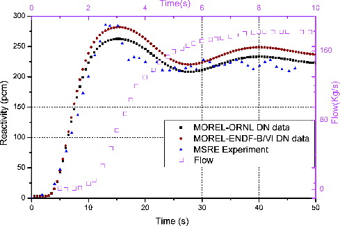
Figure 7. Reactivity compensation in the cases of fuel pump coast-down transients.
4. Applications in the neutronics analysis in TMSR
Based on the new MOREL code, some characteristics are investigated for the preliminary core design of TMSR by SINAP including the steady-state characteristics, the influence of fuel circulation on the kinetic of TMSR and fuel online reprocessing simulation. Two groups are used in this analysis and the modeling of TMSR core is shown in Section 3.1
4.1. Analysis of the steady-state characteristics
In this section, the reactivity feedback coefficient, DNP distribution and reactivity loss considering fuel circulation are analyzed for the stable fuel velocity.
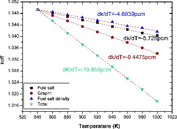
4.1.1. Reactivity feedback coefficient
The temperature reactivity coefficient in this paper is defined as . While calculating the temperature coefficient of fuel or graphite, the temperature of graphite or fuel keeps constant. Then, the temperature of fuel or graphite is changed to obtain the slopes of Keff variation. The expansion of graphite is not considered in calculation. For the fuel density coefficient, the graphite temperature keeps constant. The density and temperature of fuel salt has the following relationship.
(20)
(20) displays the reactivity coefficient of fuel salt temperature, graphite temperature and fuel salt density. We can find that those reactivity feedback coefficients are all negative and the feedback of graphite temperature is obviously stronger than that of TF and DF. From the aspect of reactivity feedback, the inherent safety is one of the characters of TMSR.
Figure 8. Reactivity coefficient of fuel salt temperature, graphite temperature and fuel salt density.
4.1.2. Delayed neutron precursors distribution and reactivity loss
In the DNP distribution and reactivity loss calculations, the fuel velocity in TMSR core is assumed to be 1 m/s with the length and diameter of external loop being 4 m and 36 cm, respectively. The fuel velocity in every graphite tube is assumed to be the same and the mass flow keeps constant in the whole loop.
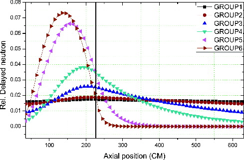
illustrates the distribution of DNPs in six families considering the fuel circulation in the external loop. It indicates that the fuel salt flow has significant influence on the DNP distribution especially for the ones with small decay constant, which decay in the reactor core before flowing back to the core.
Figure 9. Distribution of six families of delayed neutron precursor.
shows the reactivity loss of TMSR for different fuel velocity. The reactivity loss increases along with the increase of fuel velocity but tends to be stable beyond a certain fuel velocity, because the DNPs flowing out of the core are equal to that of reentering the core. It indicates that the fuel flow can be controlled to adjust the reactivity in TMSR, which is useful in accident conditions.
Figure 10. Reactivity loss under different fuel velocities in TMSR.
4.1.3. Influence of fuel circulation on the kinetic characteristics of TMSR
When the height positions of three control rods are 115 cm, the TMSR reaches criticality, which is assumed to be the beginning of neutron kinetic simulation. The same step perturbation at different fuel velocity is introduced to investigate the influence of fuel circulation on the kinetic characteristics of TMSR. The power density of the whole core is normalized to be unit at the initial time.
In the simulation, the step perturbation is introduced by the control rod withdrawal of 5 cm at the initial time and the whole transient process keeps 0.5 s. The fuel velocity keeps constant before perturbation and during the transient process. The variation of relative power is shown in .
Figure 11. Variation of relative power with step perturbation.
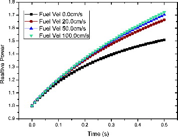
It can be seen from that the relative power increases along with time and then tend to be smooth and steady. The higher the fuel velocity, the faster the relative power increases. It is due to this reason that the effective delayed neutron fractions decrease along with the increasing fuel velocity, which is shown in .
Table 4. Changes of the effective delayed neutron fractions with different fuel velocities.
The reactivity of 249.5 pcm is introduced due to the control rods’ withdrawal. It can be seen that the introduced reactivity is more close to the effective delayed neutron fraction, the relative power of core increases more sharply and that even prompt supercritical phenomenon occurs when the introduced reactivity is larger than 459 pcm (100 cm/s fuel velocity).
The simulation shows that, for TMSR, the decrease of effective delayed neutron fraction for fuel circulation makes the neutron kinetics significantly different from that of the conventional reactor using solid fuels. Therefore, the influence of fuel circulation is not ignored in MSR transient process.
4.2. Fuel online reprocessing simulation
Fuel online reprocessing is one of the characteristics of MSR. In this section, some fuel reprocessing schemes are employed to find the characteristics of TMSR considering fuel reprocessing. We assumed all the nuclides in the core are mixed after fuel reprocessing and the consumption ratio of U-235 represents the level of burnup. The reprocessing schemes are listed in . The daily reprocessing volume is assumed to be 40 liters and the whole simulation time is nine days. Three cases are calculated and the results are shown in .
Table 5. Fuel online reprocessing schemes.
Figure 12. keff variation with burnup in three cases.
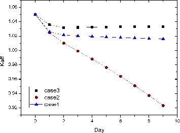
Three cases of reprocessing schemes are simulated. In case 1, there is no difference between TMSR and traditional solid fuel reactor in the burnup calculation. In case 2, all the nuclides in the fuel are mixed. In case 3, some nuclides are injected into the fuel and the density of nuclides is kept the same everywhere in the core. As shown in , we can find that the Keff of case 2 decreases faster than other two cases and case 3 changes more gently than case 1. It comes from that, after a period of time, the larger amounts of fissile nuclide in the regions with low power are redistributed into the high-power area, so more fissile nuclides will be burnt in the next period. When new fissile nuclides are added and the fission products are extracted, the Keff of reactor decreases slowly, which should be determined by the design goals to keep the reactor critical.
5. Conclusion
The MSR is characterized using the fluid-fuel, which serves as fuel and coolant simultaneously. The analytical methods used for the conventional reactors with solid fuel are not applicable for the MSRs. A new code named MOREL including 3D neutron kinetics calculation and nuclides depletion calculation is developed in this paper for the analysis of MSR. Several numerical comparisons and the experiment data gained from MSRE are used to verify MOREL. The results prove that the MOREL code can be used for the analysis of MSR.
A typical molten salt reactor TMSR designed by SINAP is analyzed in this paper, including its steady characteristics, fuel online reprocessing and neutron kinetic characteristics. For TMSR, the reactivity coefficients of temperature and salt density are all negative, which prove the inherent safety potential of MSR. The fuel salt circulation has significant influence on the DNP distribution especially for the ones with small decay constant and the reactivity loss increases along with the increase of fuel velocity.
The fuel flow makes the neutron kinetics of MSR significantly different from that of conventional reactors. For TMSR design, the power increases differently when introducing the same positive reactivity at different fuel velocities. It will be more severe when the fuel velocity becomes larger, since more DNPs are washed away in the high-speed flow.
The simulation of fuel online reprocessing is performed. The depletion of nuclides after mixing all the nuclides is faster than the one without any fuel reprocessing. Certain amount of fissile nuclides and fission products need to be injected and extracted, respectively, to keep TMSR critical.
Acknowledgements
The MSRE experimental data used in the article are referred to from MSRE operation reports of Oak Ridge National Laboratory.
Additional information
Funding
References
- MacPherson HG. The molten salt reactor adventure. Nucl Sci Eng. 1985;90:374–380.
- LeBlanc David. Molten salt reactors: a new beginning for an old idea. Nucl Eng Des. 2009;240:1644–1656.
- Mitachi K, Yamana Y, Suzuki T, Furukawa K. Neutronic examination on plutonium transmutation by a small molten-salt fission power station technical report. 1995. ( IAEA-TECDOC – 840).
- Ignatiev V. MOSART fuels and container materials study: case for Na, Li, Be/F solvent system. Paper presented at: Proceedings of the 2003 ANS/ENS International Winter Meeting (GLOBAL 2003); 2003 November; New Orleans, LA.
- MOST PROJECT. Molten salt reactor technology phase 1. Paper presented at: Proceedings of the 5th Framework Programme of European Commission; 2004.
- Serp J, Allibert Michel, Beneš Ondřej, Delpech Sylvie, Feynberg Olga, Ghetta Véronique, Heuer Daniel, Holcomb David, Ignatiev Victor, Leen Kloosterman Jan, Luzzi Lelio, Merle-Lucotte Elsa, Uhlíř Jan, Yoshioka Ritsuo, Dai Zhimin. The molten salt reactor (MSR) in generation IV: overview and perspectives. Prog Nucl Energy. 2014; Available from: http://dx.doi.org/10.1016/j.pnucene.2014.02.014
- Delpech S, Merle-Lucotte E, Heuer D, Allibert M, Ghetta V, Le-Brun C.. Reactor physic and reprocessing scheme for innovative molten salt reactor system. J Fluor Chem. 2009;130:11–17.
- Mianheng Jiang, Hongjie Xu, Zhimin Dai. [Advanced fission energy program-TMSR nuclear energy system]. Bull Chin Acad Sci. 2012;3:366–374. Chinese.
- Lapenta G, Mattioda F, Ravetto P. Point kinetic model for fluid fuel systems. Ann Nucl Energy. 2001;28:1759–1772.
- Dulla S, Ravetto P, Rostagno MM. Neutron kinetics of fluid-fuel systems by the quasi-static method. Ann Nucl Energy. 2004;31:1709–1733.
- Dulla S, Ravetto P. Interactions between fluid-dynamics and neutronics phenomena in the physics of molten-salt systems. Nucl Sci Eng. 2007;155:475–488.
- Kophazi J, Szieberth M, Feher S.. MCNP-based calculation of reactivity loss in circulating fuel reactors. Paper presented at: Proceedings of the International Conference on Nuclear Mathematical and Computational Sciences: A Century in Review-A Century Anew; 2003 April 6–10; Gatlinburg, TN.
- Wang S, Rineiski A, Maschek W. Molten salt related extensions of the SIMMER-III code and its application for a burner reactor. Nucl Eng Des. 2006;236:1580–1588.
- Yamamoto T, Mitachi K, Suzuki T. Steady state analysis of small molten salt reactor. JSME Int J Ser B. 2005;48(3):610–717.
- Yamamoto T, Mitachi K, Ikeuchi K, Suzuki T. Transient characteristics of small molten salt reactor during blockage accident. Heat Transf Asian Res. 2006;35:434–450.
- Křepel U, Grundmann J, Rohde U, Weiss FP. DYN1D-MSR dynamics code for molten salt reactors. Ann Nucl Energy. 2005;32:1799–1824.
- Křepel J, Rohde U, Grundmann U, Weiss FP. DYN3D-MSR spatial dynamics code for molten salt reactors. Ann Nucl Energy. 2007;34:449–462.
- Zhang DL, Qiu SZ, Su GH, Liu CL, Qian LB. Analysis on the neutron kinetics for a molten salt reactor. Prog Nucl Energy. 2009;51:624–636.
- Zhang DL, Qiu SZ, Su GH. Development of a safety analysis code for molten salt reactors. Nucl Eng Des. 2009;239:2778–2785.
- Lecarpentier D, Carpentier V. A neutronics program for critical and nonequilibrium study of mobile fuel reactors: the Cinsf1D code. Nucl Sci Eng. 2003;143:33–46.
- Bauman HF, Cunningham GW, Lucius JL, Kerr HT, Craven CW. ROD: a nuclear and fuel-cycle analysis code for circulating-fuel reactors. Oak Ridge (TN): Oak Ridge National Laboratory; 1971. ORNL-TM-3359.
- Aufiero Manuele. Development of advanced simulation tools for circulating-fuel nuclear reactors [ Doctoral Dissertation]. Politecnico DiMilano, Milano, Italy; 2014.
- Heuer D, Merle-Lucotte E, Allibert M, Brovchenko M, Ghetta V, Rubiolo P. Towards the thorium fuel cycle with molten salt fast reactors. Ann Nucl Energy. 2014;64:421–429.
- Stamm’ler RJJ. HELIOS methods. Studsvik Scandpower. 1998.
- Wang K, Wu H, Cao L. Analytic basis function expansion nodal method for neutron diffusion equations in triangular geometry. In : Proceedings of PHYSOR2010; 2010; Pittsburgh (PA). p. 444–455.
- Zhang DL, Qiu SZ, Su GH. Development of a steady state analysis code for a molten salt reactor. Ann Nucl Energy. 2009;36:590–603.
- Wang Kunpeng. Analytic basis function expansion method in arbitrary triangular-z node for neutron diffusion equation and its application to kinetics analysis [ Doctoral Dissertation]. Xi’an Jiaotong University, Xi'an, P.R. China; 2013.
- Lapenta G, Ravetto P, Ritter G. Effective delayed neutron fraction for fluid-fuel systems. Ann Nucl Energy. 2000;27:1523–1532.
- Huang K, Wu HC. Study on improvement of analytic depletion calculation method. Paper presented at: Proceedings of the 21st International Conference on Nuclear Engineering; 2013 Jul 29–Aug 2; Chengdu, China.
- Jiang XF, Xie ZS. Transport-burnup code systems and their applications for IAEAADS benchmark. Ann Nucl Energy. 2004;31:213–225.
- Prince BE, Engel JR, Ball SJ, Haubenreich PN, Kerlin TW. Zero-power physics experiments on molten-salt reactor experiment. Oak Ridge (TN): Oak Ridge National Laboratory; 1968. ( ORNL-4233).
- Haubenreich PN, Engel JR, Prince BE, Claiborne HC. MSRE design and operations report, Part III, nucliear analysis. Oak Ridge (TN): Oak Ridge National Laboratory; 1964. ( ORNL-TM-730).
- Delpech M, Dulla S, Garzenne C, Kophazi J, Krepel J, Lebrun C, Lecarpentier D, Mattioda F, Ravetto P, Rineiski A, Schikorr M, Szieberth M. Benchmark of dynamic simulation tools for molten salt reactors. Paper presented at: Proc. GLOBAL 2003-11-16; 2003; New Orleans, LA.
- Zhang Dalin. Research on neutronics, thermal hydraulics and safety characteristics of molten salt reactors [ Doctoral dissertation]. Xi’an Jiaotong University, Xi'an, P.R. China; 2009.