
 ?Mathematical formulae have been encoded as MathML and are displayed in this HTML version using MathJax in order to improve their display. Uncheck the box to turn MathJax off. This feature requires Javascript. Click on a formula to zoom.
Abstract
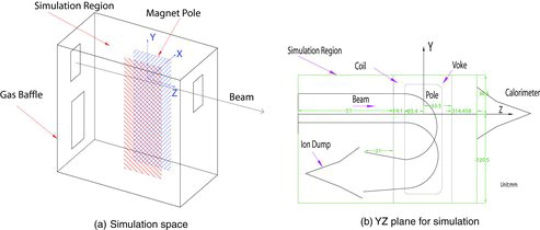
Detailed trajectories of the residual ion passing through a reflection magnet, which is installed in the Experimental Advanced Superconducting Tokamak (EAST) neutral beam injector (NBI) system to remove the residual ion from the beam path, are reported. Monte Carlo simulation has been performed to obtain estimations of the beam density on the high heat flux elements of reflection magnet. On magnet pole shielding, there are three high beam power density regions, resulting from beam line focus and corresponding to the full energy, half energy and third energy. These high heat flux regions will bring a serious challenge for steady-state operation. The simulation result indicates that the re-ionization loss is about 2.43% and the magnet pole shielding encounters a problem of beam line focus, which should be taken seriously during the steady-state operation.
1. Introduction
Neutral beam injection is a main adjuvant heating method for magnetic confining fusion research. It has been successfully adopted in different magnetic confinement devices [Citation1,2]. A positive ion-based neutral beam injector (NBI) is designed for Experimental Advanced Superconducting Tokamak (EAST).
As shown in , an NBI for a magnetic confinement device involves three stages; powerful ion beam generation, ion beam neutralization, separation and treatment of the residual ion [Citation3]. One beam line of the EAST NBI system includes two high current ion sources and it will provide 4 MW neutral deuterium beam for heating plasma and attaining an advanced tokamak operation [Citation4–6].
Figure 1. Block diagram of a neutral beam injector.
In order to accelerate the particles to the required energy, it is necessary that they are charged. Then, the resulting energetic ion beam must be neutralized to produce a neutral beam, which is capable of crossing the tokamak magnetic field and entering the plasma. The neutralization is achieved by passing the ion beam through a cold gas, in which charge exchange collisions occur. After the neutralizer, the beam includes two kinds of ion composition. One is energetic atom and the other is still charged, which is called residual ion. Due to the stray magnetic field of tokamak, the residual ion would be deflected in an uncontrolled manner and even cause significant damage to the device through a thermal overload [Citation3,Citation7]. Thus, the reflection magnet is employed for separation of residual ion before the beam passing through the injection port. Finally, the residual ion is delivered to the ion dump system.
The higher the beam energy, the lower the neutralization efficiency, and the greater the ion residual beam power. The beam will bring the heat loads for the high heat flux elements, such as magnet pole shielding, ion dump, collimator, calorimeter and so on. During the beam reflection, a few collision between beam particle and background molecule will take place. The collision will make the energetic atom ionization (named re-ionization). At the same time, it will also make the residual ion neutralization. Both of them will pose stray energetic ions and bring dicey heat load for inner elements. During the ion source conditioning, the reflection magnet has to withstand higher heat load, due to poor beam divergence angle. Therefore, the beam optics should be analyzed to confirm the heat loads on the high heat flux elements of reflection magnet. In this paper, design concepts of the reflection magnet of the EAST NBI system are described. The beam transmission is simulated by direct simulation Monte Carlo (DSMC) method and estimates of the heat loads on the high heat flux elements of reflection magnet are reported.
2. Ion beam optics analysis
2.1. Reflection of the residual ion in the reflection magnet
For positive ion-based ion source, there are three different original ion species, D1+, D2+ and D3+ [Citation8]. These ions are extracted and accelerated by the same accelerator system. Thus, they acquired the same kinetic energy. In the gas neutralizer, the reaction responsible for changing the abundance of each species is illustrated in . Symbols inside the circle denote the particle species, the superscript indicates the charge state, the subscript indicates the amount of the atom in the particle and the sign in the bracket denotes the energy of the particle. The symbol δcdab denotes the cross section of reaction, involving charge state change from a to b and the amount change of atom from c to d. When ion beam pass through the gas target, 14 sorts of particles are formed [Citation9–12]. The ion species produced in the beam path are: three major positive ions – D+(E), D+(E/2), D+(E/3); minor negative ions – D−(E), D−(E/2), D−(E/3) and minute molecular ions – D2+(E), D3+(E), D2+(2E/3), where E means the beam energy.
In order to make full use of the space of the vacuum vessel, the residual ion is reflected into an ion dump by a 180° reflecting magnet. When the ions traverse through the magnetic field of the reflecting magnet, the relationship of the ion kinetic energy and the bending radius is expressed as
(1)
(1) where m is the mass of the ion, E is the kinetic energy of the ion, B is the magnetic field intensity and the charge of the ion is q. Equation (1) shows that the reflection radius is proportional to the square root of the ion's energy, when the particle has the same charge-to-mass ratio. For the energetic beam from the neutralizer, there are three energy components for major positive ions; the full energy, the half energy and the third energy. shows the practically expected trajectories of dominant ions. The direction of the magnetic field is chosen so that the positive ions move downward to the primary ion dump, which is located under the entrance of the reflection magnet. The negative ions move upward during passing through the same magnetic field.
The dimension of beam is 12 cm×48 cm. In order to separate the residual ion from the beam path and make full use of the space in the vacuum tank, the residual ion is deflected along longitudinal direction. At the same time, the radius of the third energy ion is not less than 24 cm. When the third energy ion has the radius at 24 cm, the radii for the half energy and the full energy ion are 29.4 and 41.5 cm, respectively. Consequently, 42 cm is chosen as the reflection radius for the full energy ion.
2.2. Neutralization of the residual ion and its protection in the reflection magnet
In the reflection magnet region, the background vacuum pressure is expected as low as possible to reduce the re-ionization losses [Citation13]. However, in order to generate the ion beam and form the neutralization gas target, large amount of residual gas is puffed into the vacuum vessel from the neutralizer. Empirically, the vacuum pressure at the reflection magnet region is about 10−2 Pascal. Therefore, during bending of the residual ion, a few ions are neutralized by collision with background gas in the magnet gap, forming energetic atoms moving along the tangent direction of the bending track. The parameters of the particle tracks in the magnet gap are shown in , and the injection angles of the energetic atom in the louver region are expressed by the following equations:
(2)
(2)
(3)
(3)
(4)
(4)
(5)
(5)
Figure 2. Schematics for particle species evolution for neutral-beam injection line.
Figure 3. Major positive ions and minor negative ions hitting beam stoppers.
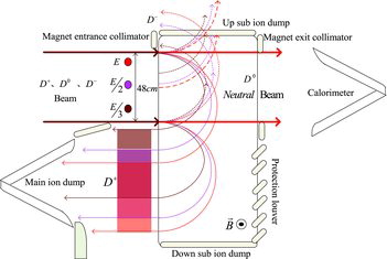
Figure 4. Trajectories of energetic atoms from neutralization of the residual ions.
For EAST NBI device, in order to pump out the gas in the magnet gap, the cryopanel is located behind the reflection magnet. Hence, at the downstream of the reflection magnet, besides the main beam path, the protection louver should be employed to prevent energetic atom from impacting on the cryopanel.
3. DSMC for beam transmission
3.1. 3D DSMC modeling
The geometric model employed in this simulation consisted of a fairly detailed representation of EAST NBI reflection magnet, as shown in . The simulation space is approximately 1.5 m in height, 0.6 m in width and 1.5 m in length. The height, width and length of the reflection magnet gap are approximately 1.5×0.18×0.71 m, respectively.
Figure 5. Three-dimensional geometric model for DSMC simulation.
Direct simulation Monte Carlo (DSMC) is a probabilistic simulation method [Citation14], which is particularly suited to the research on rarified gas dynamics. DSMC has been fully proved against plenty of experiments and become a benchmarking for other new methods used in molecular flow simulation [Citation15]. In a typical NBI, the molecular mean free path within the gas is comparable to or much larger than the distances between the components within the injector. The behavior path of an individual particle does not depend on the behavior of other molecules.
During beam operation, the incident particle on high heat flux elements will give rise to an additional source of gas due to desorption, outgassing and recombination. A crude estimate shows that a pressure of less than 10−1 Pascal must be maintained in the beam reflection region in order to keep re-ionization at an acceptable level. For EAST NBI device, two large-area cryo-condensation pumps are fixed at the upstream and downstream of the reflection magnet. Consequently, the background vacuum pressure of the beam line maintains a dynamic balance. Uniform distribution of the background gas molecules is considered for a simulation code. For those particles impacted the surface of the inner elements, the simulation progress is stopped without considering desorption, outgassing and recombination.
The behavior of the energetic ion is determined by Lorentz force, and the trajectories can be described by kinematic equations of charged particles in electromagnetic fields. For energetic atoms, the initial velocity of the particles determines their trajectories. For half-energy particles, at the same initial position, two particles will be simulated to keep the number of particle conservation. This approach is applied equally to the one-third energy particles.
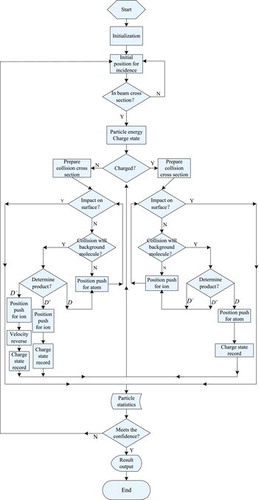
On the basis of the above analysis, the simulation code by DSMC method is developed, including one main function, 14 sub-functions and two databases for collision cross section and magnetic shielding. The flow chart of the simulation by DSMC method is shown in . At first, the initialization work for simulation is carried out, including the calculation of the reflection magnetic field, construction of cell network, preparation of the background vacuum values, setting of the initial values for simulation parameters and so on. Then, using the random number, the location of one simulation particle is determined. Through this method, the distribution of simulated particle will meet the beam intensity distribution formula [Citation16]. The validity of the simulation is determined by judging the simulated particle within the beam cross section. After that, new random number is employed to determine charge state and energy. According to the charge state, the simulated particle is treated using two different manners; kinematic equations of charged particles in electromagnetic fields and kinematic equations of uniform motion in a straight line. This simulation step has been executed until the simulated particles reach the calorimeter or ion dump or surface of inner elements. Finally, the final results of simulated particle will be recorded and a statistic calculation will be made. If the statistic result can meet the requirement of the confidence level, the simulation will be end and output the result. Or, one more simulated particle will be required and simulation will be carried out, until the confidence of the simulation is sufficed by statistic result.
Figure 6. Three-flow chart of the main function of simulation by DSMC method.
In the simulation program, several artifices are employed to resolve the details of the simulation.
From the simulation results of the vacuum distribution, it takes about 50 ms to reach the dynamic equilibrium state. Thus, for the simulation code, the background molecule is taken as the static distribution. Collisions between the particles will easily be considered.
During the beam transmission, the energetic D2+, D3+ and D2 will dissociate. The dissociation of D2+ will form two energetic single-atomic particles. To account for the conservation of the number of particles, these two energetic particles will be simulated, respectively, and its charge state, energy, trajectories and deposition position will be recorded.
The majority of the collision occurs between energetic particles and the background molecule. For non-central collision, the collision will take a small change in the direction of movement of energetic particles. During the simulation, the angular distribution is not considered for this collision process. For central collision, the stray energetic particles will be formed. The angular distribution of the production of collision is determined by evenly distributed random number between 0 and 1. The collision, between the energetic particles and inner element surface, was taken as the end of the movement of the energetic particles.
3.2. Simulation results and discussion
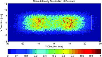
Deuterium beam at 80 keV was simulated in this study. The design value for beam parameter is applied for simulation, beam species E:E/2:E/3 = 80:14:6, and divergence angle 0.6°(X) 1.2° (Y). 0.5% was taken as the confidence requirement for the distribution of incident particles at the entrance of simulation region. About 42,000 particles were considered for the simulation, 4880 particles were located at the outside of the beam cross section, which cannot enter the simulation region and 37120 particles were simulated for its movement in the reflection magnet. The distribution of the incident particles is shown in . Using the simulation cell as standard, the beam density is normalized to the maximal value.
Figure 7. Normalized distribution of the incident particles for simulation code.
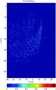
shows the deposit position for the simulated particles. The trajectories of most of the simulated particles end on the calorimeter and main ion dump. At the gap of reflection magnet, 49 particles are blocked off at the up sub ion dump and it is about 0.13%. The simulation progress shows that all of them are negative ions that are formed during passing from simulation entrance to the entrance of the reflection magnet. Besides, 74 particles are recorded at other position. All of them are scattered by the collision or the change of charge state. The simulation result is investigated at the charge state. At up ion dump, most of the particles are negatively charged, only one scattered particle is deposited at this region. For main ion dump, all of the deposited particles are positively charged. In the case of the scattering particles are not considered, position of the particle deposition is consistent with the analysis result of ion beam optics. shows the simulation result of deposit position on magnet pole shielding. In the upper half of the figure, from right to left, there are three line focus regions that are corresponding to the full energy, half-energy and third energy. These line focus region is due to the 180° deflection of the beam. At the same time, error field of reflection magnet, stray magnetic field of tokamak device and beam divergence angle will make the beam to move toward the pole shielding. This makes the beam power density to become very high and causes significant damage due to thermal overload on the pole shielding.
Table 1. Deposit position for the simulated particles.
Figure 8. Normalized deposit position on magnet pole shielding.
From the statistical result, there are 4254 collisions during the simulation progress, involving 4022 simulated particles. In these particles, 7 particles have collision with the background molecule for three times, 218 particles have collision for two times and 3797 particles just have one collision with background molecule. gives the changes in the charge state during the collision. As shown in the table, the re-ionization occurred with about 902 particles, about 2.43%. The quantity of the newly formed negative ion is very small, just 0.03%, which is consistent with the size of the reaction cross sections.
Table 2. The changes in the charge state during the collision.
4. Conclusion
The ion beam optics of the reflection magnet to be installed in the EAST NBI device to remove the residual ion from the main beam path was briefly described. The detail trajectories of the major positive ions and minor negative ions were reported. The incident angles of neutralized particle of the residual ion on the magnet protection louver were described with four formulae.
The simulation code for beam transmission in reflection region was developed by DSMC method. The beam density deposited on the inner elements was estimated. The majority of the beam power will be deposited on the calorimeter and the main ion dump, which is consistent with the experimental result. However, there is a grievous problem on the magnet pole shielding. This needs to be taken seriously during the operation, especially in the steady-state operation. From the simulation result, the re-ionization loss during passing the beam through the deflection region is about 2.43%.
From the simulation result, at the line focus region, the beam power is very high, which is much greater than that can be handled by engineering practice. Thus, in the beam operation, beam divergence angle is required to be as small as possible, which is significant to reduce lateral displacement of the beam. However the experimental results from our test bench show that it is difficult to achieve steady-state operation. Consequently, in order to meet the requirement of the steady-state operation, on one hand, the gap of the reflection magnet is increased or, on the other hand, the water-cooling structure of magnet pole shielding is improved. Hypervapotron high heat flux elements will be employed in the optimization design for the second neutral beam line for EAST.
Additional information
Funding
Reference
- Wesson J. Tokamaks. Oxford: Oxford Clarendon Press; 1997. Chapter 5, Heating; p. 273–290.
- Gibson G, Lamb W, Lauer E. Injection into thermonuclear machines using beams of neutral deuterium atoms in the range from 100 Kev to 1 Mev. Phys Rev. 1959;114:937–941.
- Speth E. Neutral beam heating of fusion plasmas. Rep Prog Phys. 1989;52:57–121.
- Hu CD. NBI team, conceptual design of neutral beam injection system for EAS. Plasma Sci Technol. 2012;14:567–572.
- Wu B, Wang JF, Li JB, et al. Neutral beam injection simulation of EAST. Fusion Eng Des. 2011;86:947–950.
- Hu CD, Liang LZ, Xie YL, Wet JL, Xie YH, Li J, Liu ZM, Liu S, Jiang CC, Sheng P, Xu YJ. Design of neutral beam-line of EAST. Plasma Sci Technol. 2011;13:541–545.
- Liang LZ, Hu CD, Liu ZM, Hu LQ. Effect of neutral beam quality on design of window in bending system. High Power Laser Part Beams. 2008;20:849–853.
- Uhlemann R, Hemsworth RS, Wang G, Euringer. Hydrogen and deuterium ion species mix and injected neutral beam power fractions of the textor-pinis for 20–60 Kv determined by doppler-shift spectroscopy. Rev Sci Instrum. 1993;64:974–982.
- Kim J, Haselton HH. Analysis of particle species evolution in neutral-beam injection lines. J Appl Phys. 1979;50:3802–3807.
- Williams ID, Geddes J, Gilbody HB. Balmer alpha emission in collisions of H, H+, H2+ and H3+ with H2. J Phys B At Mol Opt Phys. 1982;15:1377–1389.
- Williams D, Geddes J, Gilbody HB. Balmer alpha-emission in H2–H2 collisions. J Phys B At Mol Opt Phy. 1983;16:L765–L768.
- Williams JF, Dunbar DNF. Charge exchange and dissociation cross sections for H1+ H2+ and H3+ ions of 2- to 50-Kev energy incident upon hydrogen and inert gases. Phys Rev. 1966;149:62–66.
- Liang LZ, Hu CD, Xie YL, Xie YH. Modeling process of the neutral beam re-ionization loss. Chin Phys C. 2010;34:972–977.
- Bird GA. Molecular gas dynamics and the direct simulation of gas flows. Oxford: Clarendon Press; 1994. Chapter 9, Numerical methods for transition regime flows; p. 199–207.
- Shen C. Rarefied gas dynamics: fundamentals, simulations and microflows. Berlin: Springer Press; Chapter 3, Interaction of molecules with solid surface; p. 131–158.
- Liang LZ, Hu CD, Xie YL, Guo Q, Xie Y. Calculation of beam intensity distribution for the neutral beam injection in EAST. Plasma Sci Technol. 2011;13:502–505.