
Abstract
The welding of zirconium alloy components is one of the most critical processes in the fabrication of nuclear fuel rods used in pressurized water reactors. For this, various welding processes, such as gas tungsten arc welding, electron beam welding, laser beam welding, and resistance pressure welding (RPW), are used around the world. In Korea, the RPW process is being used to fabricate nuclear fuel assembly fuel rods. This study investigated changes in the weldment shape owing to welding conditions such as welding current, welding force, and overlapping. The welding soundness of the weldment was evaluated by hydraulic burst test. The welding temperature of the weld zone was measured using a thermal infrared method. Discontinuous black spots in the weld line, regarded as a non-bonding defect, were confirmed as spots caused by the carbide precipitation of zirconium during welding.
1. Introduction
Nuclear fuel rods used in pressurized water reactors (PWRs) are manufactured by loading pellets into a Zircaloy-4 tube, fitting end plugs at the ends of the tube, and sealing those parts by welding them together. The Zircaloy-4, which is the main material of nuclear fuel rods, has a narrow thermal neutron absorption cross section, exhibits adequate physical and mechanical properties in the high temperatures, and has a strong corrosion resistance for coolants [Citation1–3]. Generally, because Zircaloy-4 has a low thermal expansion coefficient, residual stress is small after welding, and as a result, there is a low probability of welding defects, such as weld cracks [Citation4]. On the other hand, Zircaloy-4 has a weakness in which it causes contamination in the nuclear reactor because of its high affinity with oxygen and nitrogen [Citation5].
One of the fuel rod's functions is to deliver the heat generated by nuclear fission in the pellet to the coolant, and in the safety side it plays a role as the primary protective barrier to shield the coolant from irradiated pellets and fission products. The nuclear fuel rod consists of UO2 pellets, a ZIRLO tube, top and bottom end plugs, plenum spring, helium gas, etc., and depending on the design, axial blanket pellets are also components of the nuclear fuel rod. Basically, the cladding materials of these nuclear fuel rods containing UO2 pellets should not be damaged during power plant operation [Citation6]. Moreover, the nuclear fuel rods act as a pressure vessel that prevents the leakage of radioactive fission products [Citation7,8]. For such reasons, the welding soundness of end plug weldment of nuclear fuel rod should be secured. Welding methods applied to the nuclear fuel assembly are gas tungsten welding (GTAW) [Citation9], resistance pressure welding (RPW) [Citation1], laser beam welding (LBW) [Citation10], electron beam welding (EBW) [Citation11], and spot welding [Citation12], as shown in . GTAW has been used in Westinghouse in USA, ENUSA in Spain, and NRI in Japan. Resistance welding has been used in AREVA in France and INB in Brazil. In case of AREVA, GTAW and LBW had been used. However, they had many trouble in reactor, so they changed welding method to resistance welding like RPW. The welding method applied to the PWR-type nuclear fuel rods in Korea is the RPW process which is highly productive and enables welding quality to be good. As for the RPW, the specific resistance and contact resistance of tubes and end plugs generate welding heat; this heat causes plastic deformation, which in turn results in weld reinforcement. There is a high possibility of the fission products leakage in the weld zone between the tubes and end plugs because internal pressure is increased by the generated fission products. Stress corrosion cracking (SCC) could be caused by weld line defects on the weld interface and the change of micro-structure in the long-time nuclear reactor environment.
Table 1. Welding methods used on different fuel assembly components.
Many researchers in Korea have been researching phenomena and features observed after welding between nuclear fuel rod end plug and tube, using methods such as LBW, GTAW, etc., since the middle of the 1980s [Citation8,Citation13–15]. However, the phenomena and features observed during the RPW process for PWR-type nuclear fuel rod have not been systematically researched, whereas most studies on the RPW process are on the non-destructive inspection application to test the welding soundness between nuclear fuel rod end plug and tube.
As mentioned above, when the extended fuel cycle and high burnup nuclear fuel rods are loaded into a nuclear reactor, the stress concentration phenomenon caused by the notched effect in the weld reinforcement by RPW can be occurred by internal pressure [Citation16]. Accordingly, the possibility of SCC occurrence is increased. Also, the residual stress generated from the weld line appeared on the weld interface by welding conditions and the change in the micro-structure, crystal structure, etc., is the cause for SCC. shows SCC induced by fuel rod end plug weldment fracture in the nuclear power plant. If SCC occurs in the weld zone of fuel rod during the operation, fission products are possible to leak in the fuel rod. This could directly lead to reactor shutdown and nuclear safety accidents.
Figure 1. Fuel rod weldment SCC fracture.
In this study, the shape changes of weld reinforcement formed between ZIRLO tube and Zircaloy-4 end plug were investigated according to welding parameters such as welding current, welding force, and cladding tube overlapping. Basic data were obtained to research SCC depending on the weld zone status after the RPW process. The welding soundness of the weld zone was verified through the burst test.
2. Manuscript preparation
2.1. Materials and welding conditions
Materials used in this study are ZIRLO tube and Zircaloy-4 end plugs. These chemical compositions are shown in . Experiment materials were selected among materials currently used for manufacturing nuclear fuel rods. The welding machine installed in the fuel rod manufacturing process was used for the test. Welding parameters chosen for this study were the welding current, welding force, and tube overlapping. Welding time was fixed at only 1 cycle (1/60 sec). It was a very short time in comparison to other welding methods. According to the change of each welding parameter, welding soundness evaluations were carried out by weld reinforcement shape and burst test. Two samples were welded under the same conditions. For one of the two samples, a burst test was carried out. For the other sample, the weld zone cross section was checked after polishing the cross section of the nuclear fuel rod specimen cut in longitudinal direction. The conditions of the nuclear fuel rod end plug welding for RPW are shown in .
Table 2. Chemical composition of ZIRLO and Zircaloy-4.
Table 3. Welding conditions for nuclear fuel rod RPW.
2.2. Weld zone temperature measurement
Welding temperature was measured by ![]() thermographic camera to improve the accuracy of temperature measurement in the non-contact way. Infrared (IR) light is electromagnetic radiation with wavelengths longer than those of visible light, extending from the nominal red edge of the visible spectrum at 700 nm to 1 mm. This range of wavelengths corresponds to a frequency range of approximately 430 THz to 300 GHz, and includes most of the thermal radiation emitted by objects near room temperature. IR light is emitted or absorbed by molecules when their rotational–vibrational movements are changed. Different detectors are used depending on IR wavelength bands (e.g. short wave, long wave). If the temperature of objects is high, then its IR wave is short; if the temperature of objects is low, then its IR wave is long. Although the thermographic camera operates like a video camera, it detects “IR energy” not “light” for imaging. After IR energy is concentrated by IR ray transmitting lenses made of materials, such as germanium, silicon, sapphire, etc., the energy collected by the sensor (IR detector) is converted into electronic signals and are shown as an image.
thermographic camera to improve the accuracy of temperature measurement in the non-contact way. Infrared (IR) light is electromagnetic radiation with wavelengths longer than those of visible light, extending from the nominal red edge of the visible spectrum at 700 nm to 1 mm. This range of wavelengths corresponds to a frequency range of approximately 430 THz to 300 GHz, and includes most of the thermal radiation emitted by objects near room temperature. IR light is emitted or absorbed by molecules when their rotational–vibrational movements are changed. Different detectors are used depending on IR wavelength bands (e.g. short wave, long wave). If the temperature of objects is high, then its IR wave is short; if the temperature of objects is low, then its IR wave is long. Although the thermographic camera operates like a video camera, it detects “IR energy” not “light” for imaging. After IR energy is concentrated by IR ray transmitting lenses made of materials, such as germanium, silicon, sapphire, etc., the energy collected by the sensor (IR detector) is converted into electronic signals and are shown as an image.
The measuring method of welding temperature is divided into two main methods: (1) the passive method in which the object generates energy by itself, and (2) the active method, which measures the response of collected energy. In the case of nuclear fuel rod end plug welding, its energy is released depending on the heat input generated by the welding current and welding force during welding. Therefore, we selected the passive method, which is more appropriate for this case. The passive methods monitor the IR emission associated with the temperature changes by the heating and cooling phenomena naturally occurring in the investigated system. The passive approach has been successfully applied, for instance, to the study of buildings and to the inspection of structures in important archaeological sites by taking advantage of the temperature variation occurred during a daily thermal cycle.
2.3. Burst test
The weld soundness of the nuclear fuel rod weldment was evaluated by the hydraulic pressure burst test. The hydraulic pressure equipment for this burst test has a special pump to apply the pressure up to a maximum of 2000 bar instantaneously. The pressure measuring program was Labview 9.0 in order to control the time and pressure during the burst test. For this experiment 6-mm welding samples were prepared. After the burst test, the macro-picture of the burst cross section was examined by the optical microscope.
2.4. Analysis equipment
After welding, the fracture shapes and types after the burst test were checked to evaluate the welding soundness of the nuclear fuel rod weldment and used optical microscopy (OLYMPUS BX51M) to check the weld reinforcement cross section. The cross-section test was performed in accordance with the quality standards for nuclear fuel rod. When a non-bonding welding defect occurred in the weld line, it was determined whether it is non-bonding after magnifying them with high magnification by the scanning electron microscopy (SEM, JEOL-7001F) analysis and its qualitative chemical composition was checked by the energy-dispersive X-ray spectroscopy (EDS, JEOL-7001F). Also, a quantitative analysis was performed by X-ray diffractometer (XRD, X’ Pert-Pro MPD) at the angle between 20° and 80° for zirconium and zirconium carbide.
3. Results and discussion
3.1. Weld reinforcement shapes and burst test results
The welding current used in this study was 10 kA and the effect of variations in the welding current was also studied in the range of 5–15 kA (±5 kA). The welding current was changed in the same condition. Hence, the welding current was increased gradually in 0.5 kA intervals. The applied welding force and overlapping were fixed as 2800 N and 0.8 mm respectively, which were found to be the appropriate values in the manufacturing process. shows the results of the hydraulic burst test results. It is confirmed that the fractures in the weld zone are occurred when the current is 9.5 kA or less. When the current is more than 9.5 kA, the burst test results meet the requirements of the rupture pressure 1200 bar. The rupture image after the burst test was observed to examine the reason why low rupture pressure was shown in the low welding current. shows an image after the burst test and the macro-section in the end plug weld zone. Fracture is observed (a) because of low heat input at the low welding current of 5 kA. When the welding current is increased from 5 to 9.5 kA, a partial fracture of the weld zone is found in the longitudinal direction at the center of end plug, which is evaluated as a defect in the weld line. This is occurred because of the concentration of hoop stress during the burst test by insufficient melting on the end plug side and poor inner reinforcement. The sound weld zone is welded with stronger welding current of 13.5 kA as shown in (c).
Figure 2. Fracture according to welding current change (electrode force: 2800 N).
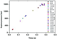
Figure 3. Image after burst test and macro-section in end plug weld zone: (a) 5 kA; (b) 9.5 kA; (c) 13.5 kA.
As already explained influence of welding current, this study confirmed that the weld reinforcement depends on the cutting position of welding specimens and the thickness of internal and external reinforcements over the current of 10 kA. This study could not confirm the existence of a proper welding condition and scope by only examining the shape of weld reinforcement. It is difficult to maintain uniform welding current and force. shows the variation of rupture pressure according to the welding force ranging from 2000 to 4000 N under the welding current of 11 kA and the overlapping of 0.8 mm. There is no significant tendency of rupture pressure according to welding force. For example, the highest rupture pressure is 3500 N, while the rupture pressure of the welding force 4000 N decreases. In general, the fracture is occurred in the base metal (tube area) and not in the weld zone. This result means that sound weldment depends on appropriate welding current. In other words, the welding current is more influential than the welding force. It can be interpreted that under the welding conditions, the interface between the tube and the end plug is partially melted, then the weld part exhibits viscos flow, which is not significantly influenced by the applied force. shows an image after the burst test and a macro-section in weld zone. Under the sufficient current of 11 kA, there were no significant differences in burst test results between the weakest welding force of 2000 N and the strongest welding force of 4000 N. However, the weld reinforcement shape becomes large when the welding force is increased. It is confirmed that end plug and tube in the PWR type nuclear fuel rods are welded by excessive welding force. The stress concentration can be made by defects in the welding zone, such as SCC during plant operation.
Figure 4. Fracture graph according to welding force change (welding current: 11 kA).
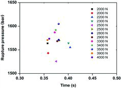
Figure 5. Image after burst test and macro-section metallographic in weld zone: (a) 2000 N; (b) 2200; N; (c) 4000 N.
The hydraulic burst test is performed to check the effects of welding overlapping. It is confirmed that the sound experimental values of the burst test are obtained under sufficient current values. shows a graph of the fracture and an image after the burst test. Weld zone fracture is occurred under welding current of 9.27 kA and the overlapping of 0.9 mm. It is confirmed that the overlapping value has no effect on weld reinforcement shape under sufficient welding current.
Figure 6. Fracture graph and image after burst test: (a) welding current 9.27 kA, overlapping 0.9 mm, welding force 3030 N; (b) welding current 8.19 kA, overlapping 0.9 mm, welding force 2991 N;(c) welding current 6.66 kA, overlapping 0.9 mm, welding force 3107 N.
3.2. Result of welding temperature measured by thermal IR camera
RPW is regarded as a solid-phase welding. It is different from GATW and LBW. Therefore, it is not easy to clearly interpret non-bonding occurred in the weld line. In addition, if there are discontinuities in the weld zone, it is usually evaluated as a defect following the quality standards. Therefore, clear evaluation criteria must be prepared. As a result, to check whether RPW is a solid-phase welding or melting welding, it was attempted to measure the welding temperature using a non-contact thermal IR camera to identify whether welding temperature is risen up to the melting temperature of 1800 °C in ZIRLO and Zircaloy-4. To calculate the exact temperature values, the temperature of the reference standard specimen is measured by induction heating and then the emissivity is determined. An STS 304 tube is used to determine the emissivity. The exact temperature is measured by a glass plate during the welding time. The thermal IR camera measures the temperature increased up to 1200 °C. shows the temperature of the reference specimen by the emissivity of 0.8.
Figure 7. Temperature of the reference specimen (emissivity: 0.84).
The temperature of the end plug is increased because electrodes wrap the whole end plug during the RPW process as shown . The welding temperature was measured directly during the welding time. The temperature is risen over the melting point (1800 °C) regardless of the value of the welding current as shown in . As for this result, it is confirmed that in the RPW process, the tube and end plug are instantaneously fusion-welded. The weld line at macro-section shown in actually is the fusion line.
Figure 8. Thermal IR image during the RPW process: (a) image of the thermal IR measurement; (b) temperature image of weldment.
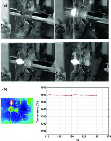
Figure 9. Temperature of welding zone during the RPW process.
Figure 10. Marco-section metallographic of fuel rod weldment.
3.3. Microstructure of weld zone
After performing the burst test of welding specimens, black dots were observed on the cross-section metallographic specimen as shown in . It was evaluated as a defect in the weld zone because it looked like non-bonding. However, in general, the cause ![]() of these black dots are known as porosity or precipitate made by oxide or carbide. The black dots in the fusion line were magnified by SEM to identify it. The EDS analysis of the black dots was performed to identify the compound of this area.
of these black dots are known as porosity or precipitate made by oxide or carbide. The black dots in the fusion line were magnified by SEM to identify it. The EDS analysis of the black dots was performed to identify the compound of this area.
Figure 11. Weld line defect of the fusion line in the fuel rod weld zone.
The black dots were magnified 10,000 times using SEM as shown in . The black dots were not non-bonding but precipitate covered on the weld zone. Several cracks were found in the middle of the precipitate. Cracks of precipitate did not show the burst test failure in the weld zone. Those things had no effect on the burst test, but they could exert influence on a negative effect, such as stress corrosion in the reactor. The welding quality standards have to be prepared so that precipitates are not allowed in the welding process. Furthermore, the EDS analysis was performed to identify the cause of the fusion line defect as shown in . shows the results of the EDS analysis in the fusion line defect. The XRD analysis was performed to confirm the compound of fusion line defect. shows the results of the XRD analysis of the weldment. The main diffraction peak of XRD analysis is zirconium material, while there is a weak diffraction peak at 32.3° indicating zirconium carbide as depicted in . This result means that the precipitation of zirconium carbide is made by carbon impurities during the welding process.
Table 4. Results of the EDS analysis in the fusion line defect.
Figure 12. Crack of the weld line defect in fuel rod weld zone: (a) x10000 (SEM image); (b) x3000 (TOPO method); (c) positions of EDS analysis.
Figure 13. XRD pattern of weld part (inset is XRD pattern of “B” section).
As a result of SEM data with compo mode on the defect in the weld part, the dark dots are shown like black because of carbon. In positions 8 and 10 analyzed with EDS in , it is found that the carbon content is higher than zirconium content, and carbon content in position 11 is also high. Therefore, the crack is assumed to be occurred in the welding zone because of carbon-induced precipitation of zirconium carbide. Zirconium alloys usually contain zirconium and carbon. Therefore, this carbide precipitation is not a foreign material but zirconium alloy's material.
4. Conclusion
In this study, the welding was performed by several welding parameters in order to obtain basic data for the RPW process used in the fabrication of the PWR-type nuclear fuel rods. This study found that the most important parameter in the RPW process was the welding current. Also, after performing burst tests on the weld zone and examining the cross sections of specimen, discontinuous black spots were observed on the weld zone. Therefore, it is considered that new standards should be prepared to evaluate the effects of carbide precipitate on discontinuous black spots. The welding temperature of end plug welding in RPW was measured by the thermal IR imaging. The temperature of the weld zone was higher than zirconium alloy's melting temperature of 1800 °C. The welding is basically performed by melting. It was confirmed that the welding temperature was close to the melting temperature of the base materials of PWR fuel rods, although the welding time of 1 cycle (1/60 sec.) was short in the weld of PWR-type nuclear fuel rods. The discontinuous black spots in the weld line were regarded as non-bonding defects. This study confirmed that the black spots were caused by carbide precipitation of zirconium during welding by SEM, EDS, and XRD analyses. Zirconium alloys usually contain zirconium and carbon. Therefore, this carbide precipitation is not a foreign material but zirconium alloy's material.
Acknowledgements
This work was supported by the National Research Foundation of Korea (NRF-2014M2A8A5021935) grant funded by the Korea government (MISP).
References
- Kumar NAPK, Azpunar JA, He Z. Microstructural studies and crystallographic orientation of different zones and δ-hydrides in resistance welded zircaloy-4 sheets. J Nucl Mater. 2011;414:341–351.
- Cheadle BA, Coleman CE, Licht H. CANDU-PHE pressure tubes: their manufacture, inspection, and properties. Nucl Technol. 1982;57:413–425.
- Murty KL, Charit I. Texture development and anisotropic deformation of zircaloys. Prog Nucl Energy. 2006;48:325–359.
- Raj B, Mudali UK. Materials development and corrosion problems in nuclear fuel reprocessing plants. Prog Nucl Energy. 2006;48:283–313.
- Selmi N, Sari A. Study of oxidation kinetics in air of zircaloy-4 by in situ X-ray diffraction. Adv Mater Phys Chem. 2013;3:168–173.
- Herranz LE, Feria F. Spent fuel rod splitting due to UO2 oxidation during dry storage: assessment of the database. Prog Nucl Energy. 2009;51:201–206.
- Ram V, Kohn G, Stem A. CO2 laser beam weldability of zircaloy-2. Weld J. 1986;65:33–37.
- Kim SS, Kim DH, Kim CJ, Lee JM. Investigation of zircaloy-4 weldability using a pulsed Nd: YAG laser. J KWJS. 1991;9:23–31.
- Perez TE, Saggese ME. Welding structures in gas tungsten arc-welded zircaloy-4. Metallography. 1982;15:43–52.
- Song KN, Kim SS, Lee SH, Lee SB. Laser welding unit for intersection line welding of spacer grid inner straps and its application. J Laser Micro/Nano Eng. 2007;4:11–17.
- Shankar AR, Raju VR, Rao MN, Mundali UK, Khatak HS, Ray B. Corrosion of zircaloy-4 and its welds in nitric acid medium. Corros Sci. 2007;49:3527–3538.
- Tao W, Cai C, Li L, Chen T, Wang TL. Pulsed laser spot welding of intersection points for zircaloy-4 spacer grid assembly. Mater Des. 2013;52:487–494.
- Kim SS, Kim JH, Kim HK. Evaluation of endcap welding test for a nuclear fuel rod having external and internal tube structure. In: Kim SS, Kim, JH, Kim HK, editors. Proceedings of KSME; 2008 Jun 4–5; Daejeon, Korea: KAERI. 2008.
- Kim WG, Kim SS, Lee YC, Lee YD, Lee WJ. A study on the non-destructive inspection for end closure welding of nuclear fuel elements of irradiation test. Proceeding of Spring Conference of KWJS; 2004 May 20–21; Jeju, Korea.
- Kim SS, Kim EG, Lee JW, Yang MS, Lee YH. A study on Zr-4 laser welding for attachment of bearing pads of nuclear fuel element. Proceeding of Conference of KWJS; 2001 May 3–4; Seoul, Korea.
- Was GS, Ampomrat P, Gupta G, Teysseyre S, West EA, Allen TR, Sridharan K, Tan L, Chen Y, Ren X, Pister C. Corrosion and stress corrosion cracking in supercritical water. J Nucl Mater. 2007;371:176–201.