
 ?Mathematical formulae have been encoded as MathML and are displayed in this HTML version using MathJax in order to improve their display. Uncheck the box to turn MathJax off. This feature requires Javascript. Click on a formula to zoom.
Abstract
In case of the boiling and drying accident of a high-level liquid waste (HLLW) tank, a large amount of ruthenium (Ru) will be volatilized. In order to suppress the release of radioactive materials to the environment, the vapor may be led to the neighboring cells in which it will contact with the cell walls to be partially condensed. To understand the behavior of Ru in this situation, we have prepared an experimental apparatus. It consists of a small tank in which 60 mL simulated HLLW is heated to dryness, a 9.6 L stainless steel box which mimics the neighboring cell accepting the vapor from the small tank, and a condenser where the vapor coming out from the box is cooled to collect the condensate. The results show that more than 99% of the volatilized Ru is removed from the vapor in the box if its temperature is below about 120 °C.
1. Introduction
In the safety assessment of the boiling and drying accident in high-level liquid waste (HLLW) tanks, which is one of the major accidents designated by the Nuclear Regulation Authority [Citation1], the behavior of ruthenium (106Ru) attracts much attention since it shows a significant volatility.
In the study of Ru volatility from the simulated HLLW (called SHLLW even after dried), Sasahira et al. showed that Ru(NO)(NO3)3 in HNO3 solution could be oxidized to volatile RuO4 and the reaction rate increased greatly with acid concentrations above 7.5 M [Citation2, 3].
Philippe et al. [Citation4] carried out experiments using actual HLLW and showed that, during boiling and drying up to 160 °C, the airborne release fraction (ARF) [Citation5] of Ru was 12%, whereas those of nonvolatile 137Cs and α-emitters were both about 1 × 10⁻³%. The ARF is defined here as the ratio of the amount of Ru flowing out of the vessel to the total amount of Ru initially contained. Ten thousand times larger ARF of Ru than those of nonvolatile elements is explained by its volatility. Nonvolatile substances are transferred as liquid aerosols to the upward vapor flow at the boiling liquid surface.
In case of the accident, the vapor coming out from the HLLW tanks will be led to the neighboring cells to mitigate its consequence [Citation1]. However, little is known as to the fate of the volatilized Ru in the cells along the transfer pathways. Therefore, we have carried out experiments to know the leak path factor (LPF) [Citation5] of the volatilized Ru when SHLLW is heated and the vapor is discharged to a model cell. Here, the LPF is defined as the ratio of the amount of Ru flowing out of the cell to that flowing in.
2. Experimental
2.1. Apparatus
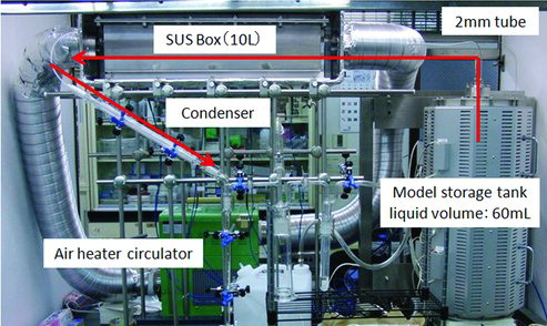
The schematic diagram of the apparatus is shown in and the photograph in . The apparatus consists of three major parts connected in series; a model tank containing SHLLW, an SUS (Steel Use Stainless) box which simulates a cell and receives the vapor from the model tank, and a condenser where the vapor coming out from the SUS box is cooled to liquid and collected in small glass bottles. In addition, an Ru absorber containing HCl and ethanol is added to recover Ru leaked from the condenser. Details of each part are given below.
Figure 1. Schematic diagram of the experimental apparatus connected. (1) Electric furnace, (2) glass cylinder, (3) SUS tube, (4) container of the SUS box, (5) SUS box, (6) air heater circulator, (7) Liebig condenser, (8) sample bottle, (9) Ru absorber (HCl + ethanol), and (10) SHLLW.
Figure 2. Photograph of the experimental apparatus. The vapor generated in the tank is continuously transferred as shown by the arrows. Thermal insulators are removed in this photograph.
2.1.1. Model tank
The SHLLW was prepared referring to the ORIGEN2 result for spent PWR fuels of 45,000 MWd t−1 and six-year cooling and assuming 0.4 m3 HLLW production per 1 t spent fuel. The composition is shown in . The Ru reagent with the trade name of ruthenium nitrate (Tanaka Kikinzoku Kogyo) was analyzed by thermogravimetry, the result of which suggests that the chemical form of the reagent is ruthenium nitrosyl nitrate. The SHLLW of 60 mL was stored in an inner glass cylinder with a diameter of 24 mm and a height of 450 mm, which was set in an SUS tube and heated in an electric furnace. The heating rate of SHLLW was so adjusted as to give a superficial vapor velocity of 0.013 m s−1. This corresponds to the vapor velocity in actual tanks in which HLLW with decay heat of 5 W L−1 [Citation6] is stored.
Table 1. Composition of SHLLW*.
It took 4.5 hours to increase the SHLLW temperature from 25 to 120 °C. When the temperature reached about 120 °C, the heating rate increased to about 3 °C min−1 until the temperature reached 400 °C. The reason for rapid increase above 120 °C is that most of the liquid had been evaporated, resulting in smaller heat consumption for evaporation.
2.1.2. SUS box
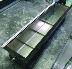
In the boiling accident, the vapor discharged from the HLLW tanks is assumed here to be led to the neighboring cells, where it is mixed with the ambient air and comes to contact with cold cell walls, where a significant amount of the vapor would be condensed. Along with the condensation, the volatilized Ru may undergo chemical reactions with nitrogen oxides and dissolution into the condensed liquid. To simulate such situation in the cell, we have prepared a model box made of SUS304, with the size of 126 × 128 × 596 mm and the inner volume of 9.6 L, whose appearance is shown in . The residence time of the vapor in the SUS box is about 30 min while boiling continues. The residence time, however, will become longer above 120 °C as a result of less vaporization.
Figure 3. Appearance of the SUS box.
The SUS box was set inside a larger box and heated air was circulated between the SUS box and the outer larger box for controlling the SUS box temperature. The temperatures of the SUS box were observed at four points at the top outside, at four points at the bottom outside, and at the center of the box inside. The temperature at the most upstream point at the top was used as the control variable. The measured temperatures at nine points lied within ±2 °C around the average.
The vapor from the tank was sent to the SUS box through a 2-mm internal diameter polytetrafluoroethylene (PTFE) tube wrapped in a ribbon heater, the temperature of which was controlled to be the same as that of SHLLW until 200 °C. Then, the temperature was kept at 200 °C.
The box temperature was controlled initially to be the same as that of SHLLW in the tank. When the temperature reached a desired value between 100 and 200 °C, it was kept at that value, although the waste temperature was increased up to 400 °C.
The vapor discharged from the SUS box was sent to a Liebig condenser through a 2-mm internal diameter PTFE tube at room temperature. The condenser was cooled by cold water of 15 °C.
2.2. Measurement of Ru
The condensed liquid in the Liebig condenser was collected by every 3 mL in small glass bottles. At the end of each run, the vapor remaining in the SUS box was recovered by sending 30 L air for several minutes. After each run, the condenser was rinsed with 1 mol L−1 HNO3 to recover soluble Ru remaining on its wall and its amount was measured. The PTFE tube connecting the box and the condenser was boiled in hot 1 mol L−1 HNO3 but no Ru was detected in the solution.
The lid of the SUS box was then removed and liquid remaining in the box was collected by a pipette and the residual liquid was wiped out with a filter paper. The inside wall of the box was first scraped off with a sand paper and then wiped with filter papers moistened with 7 mol L−1 HNO3. These papers were dipped in 7 mol L−1 HNO3, followed by heating, and dissolved materials were recovered. The amounts of Ru in all samples recovered were analyzed by the inductively coupled plasma mass spectrometer.
2.3. Preliminary ARF experiment
In order to know the vapor and Ru flowing rates into the SUS box, the PTFE tube from the model tank was directly connected to the Liebig condenser. From this experiment, the vapor production rate especially above 120 °C and the ARF of Ru were obtained.
3. Results and discussion
The preliminary experiment showed that the volatilization of Ru and the formation of NOx gas began at about 120 °C, by this time about 70% of the initial volume of SHLLW having been evaporated, and that the condensates could be collected even at temperatures around 280 °C. The ARF of Ru in this experiment was 4.9%. Although about 0.6% of the Ru discharged from the model tank was recovered from the PTFE tube connecting the model tank and the box, this value was not included. Thus 4.9% Ru flows into the SUS box in the box experiment.
The results of the SUS box experiment, that is, the amounts of Ru recovered in the condensates at the Liebig condenser (α), those recovered in the box inside (β), and the values of α/(α + β) at various box temperatures, are shown in . In the table, we use the run name BOX-nnn, where ‘nnn’ means the steady temperature (°C) of the box. The runs are listed in the increasing order of the box temperature, as shown by the run names. In the Ru absorber installed after the condenser, no Ru was detected in all runs. Ru amount remaining in the gas phase in the SUS box at the end of an experimental run, which was swept out by sending air and recovered at the condenser, was 3% of (α + β) in Box-200, 0.2% in Box-145, and less than 0.03% in the other runs, and these amounts are included in each α.
Table 2. Ru-LPF of experimental runs at different temperatures.
Here, the Ru-LPF is defined as
Precisely, it will be defined as
where γ is the amount of black deposition observed in the SUS box, which is estimated as RuO2 produced from RuO4. Most of the black deposition could be recovered by the sand paper treatment, but this could not be dissolved by the heated nitric acid. Therefore, the amount for γ could not be measured but it would not be so much, because of the following reason.
The values of (α + β) scatter between 20,000 and 31,000 μg, with the average of 25,500 μg and the relative standard deviation of 14%. The ratio of 25,500 μg to the initial total amount in the SHLLW is 4.8%, a good agreement with the ARF value of 4.9% obtained in the preliminary experiment. This suggests that most of the Ru flowing into the box was recovered and measured as (α + β) and, therefore, the amount of γ is not so large.
shows the Ru-LPF as a function of the box temperature. LPF increases with the temperature from 0.1% at 110 °C to 50% at 200 °C. This means that 99.9% of the total Ru entering the box was trapped inside the box when the box temperature was maintained at 110 °C, and only half was trapped in the box at 200 °C.
Figure 4. Ru-LPF as a function of the SUS box temperature.
Condensed liquid remained at the bottom of the box after the runs at Box-110 and Box-120, but no liquid remained in the other runs. However, even in these other runs, the temperature rose through 110 and 120 °C and, therefore, condensed liquid remained initially and evaporated later. This was confirmed by marks of liquid drip on the inside wall of the box. Considering that the rate of thermal decomposition of RuO4 to RuO2 is reported to increase with increasing temperature [Citation7], the temperature dependence of LPF shown in suggests that Ru trapping in the box is controlled not by the thermal decomposition of RuO4 but by the dissolution into the condensed liquid. When the RuO4 discharge began, the vapor from the tank colored dim brown of NO2. If a part of the NO2 is dissolved in the condensed liquid, resulting nitrous acid in the condensed liquid would reduce RuO4 and accelerate its dissolution.
Now, we examine the Ru-ARF of this experiment. The value of 4.9% may seem different from the reported value of 12% by Philippe et al. [Citation4]. The value of 12% includes fractions of insoluble Ru (RuO2) deposited on the glass tank wall (1.7%) and soluble Ru recovered from the rinse solution of the glass tube between the glass tank and the condenser (<3.3%), both values in parentheses measured after the run. Even if subtracting these values, the remainder seems still larger than the present value.
We consider that this difference would be primarily due to difference in the heating rate of the SHLLW. In the present experiment, it took 1.5 hours to increase the temperature from 120 to 400 °C, whereas in the experiment by Philippe et al. it took 60 hours from 120 to 160 °C. In a recent report, it is described that, if the heating rate is as fast as that in the present experiment, the Ru-ARF is suppressed to around 3%, whereas an experiment with 20 times slower heating rate gave 9% ARF [Citation8].
The effects of the box wall on the behavior of Ru and a comparison of the behavior between Ru and nonvolatile elements will be presented and discussed in a coming full paper.
References
- The Rules for Spent Fuel Reprocessing Business, ministerial ordinance issued by the Prime Minister's Office, No.10, March 27, 1971; amended in December 6, 2013.
- Sasahira A, Kawamura F. Formation rate and gas-liquid equilibrium of RuO4. J Nucl Sci Technol. 1988;25:472–478.
- Sasahira A, Hoshikawa T, Kamoshida M, Kawamura M. Transfer of ruthenium from a simulated reprocessing solution to gas phase during continuous distillation. J Nucl Sci Technol. 1996;33:753–757.
- Phillipe M, Mercier JP, Gue JP. Behavior of ruthenium in the case of shutdown of the cooling system of HLLW storage tanks. In: First MW, editor. Proceedings of the 21st DOE/NRC Nuclear Air Cleaning Conference; 1990 Aug; San Diego (CA): The Harvard Air Cleaning Laboratory, p. 831–843; 1991.
- US Nuclear Regulatory Commission. Nuclear fuel cycle facility accident analysis handbook. 1998. ( NUREG/CR-6410).
- Miyata T, Takebe K, Tamauchi Y, Nakano M, Hayashi Y, Sekine K, Matsuoka S, Tanaka F, Kuroiwa K, Kurosu K, Hayashi K. [Application of probabilistic safety assessment to Rokkasho reprocessing plant (II) – the occurrence frequency of boiling accident of highly active liquid waste]. Trans At Energy Soc Jpn. 2008;7:85–98. Japanese.
- Mun C, Cantrel L, Madic C. Study of RuO4 decomposition in dry and moist air. Radiochim Acta. 2007;95:643–656.
- [Management group on the study of the behavior of released radioactive materials in a reprocessing plant]. 2014. Japanese. Available from: http://iss.ndl.go.jp/books/R100000002-I025394315-00