 ?Mathematical formulae have been encoded as MathML and are displayed in this HTML version using MathJax in order to improve their display. Uncheck the box to turn MathJax off. This feature requires Javascript. Click on a formula to zoom.
ABSTRACT
The drilling or cutting of resolidified fuel debris required to defuel the Fukushima Daiichi nuclear power station is certain to generate debris dust. This paper focused on drilling resolidified fuel debris in water and conservatively confirmed by criticality calculations that neutron multiplication effect is higher if debris dust is suspended separately from the debris rather than if it is suspended closely around the debris. No use of vacuuming of debris dust, borated water, and active components was assumed in this study. Also, this paper confirmed that the use of a debris dust guide effectively and passively limited the increase in neutron multiplication by debris dust because the guide distributes dust particles so flatly that sufficient neutron leakage limits neutron multiplication even if the volume fraction of the particles in water reaches the optimum condition. In the actual defueling operation at the nuclear power station, the use of a flatter debris dust guide will be more effective to prevent local recriticality concurrently with the careful control of the mass of debris dust. The physics and ideas in this paper should be applicable to other defueling technologies such as laser cutting as long as debris dust is generated and suspended in water.
1. Introduction
1.1. Background
Defueling operations upon existing fuel debris at Fukushima Daiichi nuclear power station are planned and will be initiated in 2021 according to the mid- and long-term roadmap for decommissioning the plant [Citation1]. Considering the defueling experience at Three Mile Island Unit 2 (TMI-2) [Citation2], the defueling operation at Fukushima Daiichi will inevitably include activities such as cutting and drilling of resolidified fuel debris to remove the debris from the damaged primary containment vessel and reactor pressure vessel.
Recent studies have been developing four technologies for the defueling work: drilling, laser cutting, plasma cutting, and abrasive water jet cutting. Drilling was used for the defueling operation at TMI-2 to pulverize resolidified fuel debris in borated water [Citation2], and filtration of borated water to remove microbes and fine particles generated by the drilling operation was essential to maintaining water clarity [Citation3]. Laser cutting and plasma cutting are technologies that locally heat, melt, and cut target materials. However, if they are applied to ceramics such as fuel debris consisting of uranium dioxide, the irradiated materials are fractured into fragments including fine particles less than 1 mm in diameter by visual observation according to the experimental results of laser cutting of ceramics [Citation4]. Abrasive water jet cutting works by injecting abrasive onto target materials using high-pressure water jet. Consequently, it generates dust from the target materials resulting from direct interaction between abrasive and the target materials. Therefore, if any of the four technologies is applied to the defueling operation, the generation of fuel debris dust will be unavoidable.
1.2. Motivations
Debris dust generated by defueling activities such as drilling of resolidified fuel debris can increase neutron multiplication when it is mixed with water because water thermalizes neutrons. In other words, the mixing of debris dust with water can increase the possibility of unintentionally reaching recriticality during the defueling operation. The possibility has been indirectly confirmed by calculating effective multiplication factors for debris bed consisting of a mixture of granular fuel debris, structural materials, and water accumulated in the lower head of the damaged reactor pressure vessel [Citation5]. Also, the use of boron pellet or boron gel has been proposed to prevent the recriticality of fuel debris [Citation6]. However, little information is available so far on the relation between distributions of the debris dust suspended around resolidified fuel debris and increases in neutron multiplication. The relation is meaningful to study how to reduce the possibility of unintentionally reaching recriticality during the defueling operation.
The main measures to limit neutron multiplication by debris dust and to prevent recriticality include:
| 1. | vacuuming debris dust in parallel with defueling activities to prevent mixing of debris dust with water, | ||||
| 2. | continuous circulation of borated water in the primary containment vessel to absorb thermalized neutrons, and | ||||
| 3. | limitation of diffusion of debris dust in water to prevent the optimum volume fraction of debris dust particles in water. | ||||
On the other hand, a high dose rate in the damaged primary containment vessel or reactor pressure vessel makes it difficult not only to fully investigate the spatial distribution and composition of fuel debris in the vessels by remote-operated camera but also to repair the damaged vessels to stop water leakage and enable the continuous circulation of borated water. In short, it is possible that the main measures could not work as expected; thus, the following conditions should be assumed in planning the defueling operation in terms of defense-in-depth:
| 1. | A part of the debris dust generated by defueling activities such as drilling of resolidified fuel debris could leak to the surrounding water even if they are performed in tandem with vacuuming of debris dust. | ||||
| 2. | Continuous circulation of borated water in the damaged primary containment vessel may not be feasible. | ||||
1.3. Purpose
In light of these assumptions, first this paper identifies the distribution of debris dust that has higher neutron multiplication effect during drilling of resolidified fuel debris by comparing two conservative debris dust distributions. Neutron multiplication factors keff depend on conditions of resolidified fuel debris and of the drilling operation. Therefore, this paper focuses not directly on keff but on the change in keff relative to the initial keff during the drilling operation. Second, this paper proposes a passive measure to reduce neutron multiplication by debris dust without vacuuming debris dust in tandem with drilling, circulating borated water through the system, or using any active components other than the drilling machine. Technologies and methodologies that will be applied to the defueling operation at Fukushima Daiichi nuclear power station have been under study yet. However, this paper focuses on the drilling of resolidified fuel debris because it became a proven technology in the defueling of TMI-2. Also, the drilling operation was assumed to be conducted in pure water for conservative examination of the issue. The physics and ideas behind all calculations in this paper should be applicable to other defueling technologies such as laser cutting and plasma cutting as long as debris dust is generated and is suspended in water.
2. Analysis methodology
2.1. Analysis conditions and assumptions
2.1.1. Initial conditions of resolidified fuel debris
summarizes the initial conditions of resolidified fuel debris. The resolidified fuel debris was assumed subcritical before drilling operation. The distribution, configuration, and composition of fuel debris at Fukushima Daiichi nuclear power station have been under investigation. Therefore, the initial conditions were conservatively defined in principle and each condition is justified as follows. Spherical fuel debris was selected to maximize fission reactions, and the sphere radius of 100 cm was determined to reach a deep subcriticality where keff (νp) is 0.782 through criticality calculations. Fuel debris consists only of uranium dioxide with no porosity and with no structural materials or neutron absorbers to maximize neutron multiplication. Enrichment of uranium 235 is 4.9 wt% with no consideration of burnup and is equivalent to the highest enrichment of the BWR STEP 3 fuel assembly used for the Fukushima Daiichi nuclear power station.
Table 1. The initial condition of resolidified fuel debris.
2.1.2. Drilling operation for resolidified fuel debris
As mentioned in Section 1.2, a part of debris dust generated by drilling resolidified fuel debris could leak to the surrounding water even if it is performed in tandem with vacuuming of debris dust. Also, continuous circulation of borated water in the damaged primary containment vessel may not be feasible. Therefore, we assumed that the drilling operation does not use borated water or vacuuming of debris dust in parallel with drilling. It was also assumed that all of resolidified fuel debris drilled by a drill bit is suspended in water in the form of a debris dust particle.
This study uses two parameters for drilling resolidified fuel debris: the diameter and the depth of the drill hole. The diameter of the drill hole was assumed to be 10 cm or 20 cm in order to examine the effect of the mass of debris dust on neutron multiplication. These values are sampled from the fact that the defueling operation at TMI-2 used a solid face drill bit with an 11.4-cm diameter [Citation7]. On the other hand, the depth of the drill hole was fixed to be identical to the diameter of the spherical resolidified fuel debris, i.e. 200 cm, to maximize the mass of debris dust.
2.1.3. Size and distribution of debris dust particles
The size of debris dust particles generated by drilling resolidified fuel debris has not been confirmed yet. Although a filtration test at TMI-2 used a stainless steel mesh with a nominal pore size of 0.5 µm to remove suspended dust and microbes from reactor coolant [Citation3], little information is available on the distribution of the size of debris dust particles generated by the drilling operation at TMI-2. An experimental result of laser cutting of ceramics showed the irradiated materials were fractured into fragments including fine particles less than 1 mm in diameter by visual observation [Citation4]. Even though this is an experimental result of laser cutting of ceramics, the result provides knowledge on how ceramics can be fractured. On the other hand, previous studies on criticality safety of fuel debris showed that the highest neutron multiplication was obtained when fuel debris particles with the diameter of a few centimeters were mixed with water [Citation5,Citation6]. However, it will be unrealistic that fuel debris particles with the diameter of a few centimeters are suspended in water because of their weight. Therefore, all debris dust particles were assumed to be identical to each other and the radii of all the particles were assumed to be 1000 µm (1 mm) or 100 µm in order to examine the effect of the size on neutron multiplication.
Also, debris dust particles generated by drilling resolidified fuel debris were assumed to be randomly distributed in water. In the actual defueling operation at Fukushima Daiichi nuclear power station, water flow in the primary containment vessel or reactor pressure vessel can be formed by the combination of at least two flows: a reactor coolant flow and a flow resulted from defueling activities such as drilling and vacuuming. Therefore, a random distribution of debris dust particles is more consistent with the expected water flow. Section 2.2.2 elaborates what debris dust distributions are considered in order to identify the distribution of debris dust that maximizes neutron multiplication effect in drilling resolidified fuel debris.
2.2. Analysis cases
2.2.1. Criticality analysis for infinite distribution of debris dust
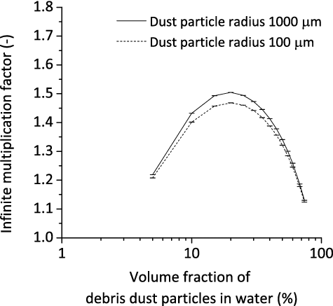
Criticality calculations for an infinite distribution of debris dust were used to examine the effect of size of debris dust particles on neutron multiplication. The infinite criticality calculations also examined the optimum volume fractions of debris dust particles in water for the assumed particle radii.
2.2.2. Criticality analysis for finite distribution of debris dust
The distribution of debris dust that would maximize neutron multiplication effect in drilling resolidified fuel debris was examined by comparing the following two patterns of distribution:
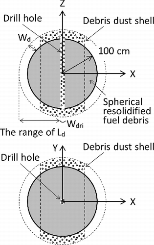
| (A) | Debris dust is randomly suspended in the drill hole and in a shell surrounding the spherical resolidified fuel debris as shown in | ||||
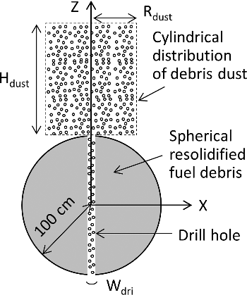
| (B) | Debris dust is randomly suspended in the drill hole and in a cylindrical space separate from the spherical resolidified fuel debris as shown in | ||||
Pattern A of debris dust distribution is selected to simulate debris dust that is swirled up by upward flow resulted from the drilling operation, falls down by gravity, and then is suspended around the spherical resolidified fuel debris. This pattern enhances the neutron coupling between debris dust and the spherical resolidified fuel debris. Criticality calculations were performed to examine the highest increase in neutron multiplication by suspended debris dust at different thicknesses Wd and widths Ld of debris dust shell. The thickness Wd was assigned as 1, 5, and 10 cm and the width Ld was assumed to vary from 1 cm to the length that would completely cover the spherical resolidified fuel debris. The physical meaning of changing Wd and Ld was to change the spatial effect of debris dust distribution on neutron multiplication and to change the volume fraction of debris dust particles in water.
Pattern B of debris dust distribution is selected to simulate debris dust that is being swirled up by upward flow resulted from the drilling operation above the spherical resolidified fuel debris. This pattern enhances neutron multiplication by suspended debris dust. A spherical distribution of debris dust was not assumed because of a simplified water flow which considers only upward flow resulted from the drilling operation. Criticality calculations were performed to examine the highest increase in neutron multiplication by suspended debris dust at different radii Rdust and heights Hdust of the cylindrical space. The radius Rdust was assigned as 10, 20, 30, 40, 50, and 100 cm and the height Hdust was changed to cover a wide range of volume fractions of debris dust particles in water.
The effect of the mass of debris dust on neutron multiplication was also examined for both patterns of debris dust distribution by changing the diameter of the drill bit Wdri to 10 and 20 cm.
2.3. Analysis code and nuclear data
All criticality calculations in this study used a continuous energy neutron transport Monte Carlo code MVP2.0 [Citation8] to handle various geometries including random distribution of debris dust particles suspended in water using a statistical geometry model in the code. Infinite and effective multiplication factors were estimated only by prompt neutrons to focus on the prompt super criticality that would be reached instantaneously during the drilling operation. The number of neutron histories per batch and the number of batches used in the criticality calculations were set to tally neutron multiplication factors with a standard deviation σ on the order of 0.01%. Also, JENDL-4.0 [Citation9] was used as the latest nuclear data library.
3. Results and discussion
3.1. Infinite multiplication factor for distribution of debris dust
compares the infinite multiplication factors for random debris dust distribution considering 100 and 1000 µm for the radius of the debris dust particles. The horizontal axis in the figure is a volume fraction of debris dust particles in water. Infinite multiplication factor peaks around the volume fraction of 20%. Also, the infinite multiplication factor for the radius of 1000 µm was higher than that for 100 µm. This difference qualitatively indicates that neutrons in a debris dust particle with the radius of 1000 µm have higher fission probability than those in a debris dust particle with a radius of 100 µm if the volume fractions for each radius are identical to each other. This is attributed to a neutronic feature that self-shielding effect of uranium 238 resonance absorption is more predominant for smaller debris dust particles. In other words, infinite multiplication factors for smaller particles heterogeneously mixed with water are more close to that for homogenous mixtures of uranium dioxide and water. On the other hand, larger particles provide less effect of the resonance absorption. Also, as mentioned earlier, fuel debris particles with the radius of a few centimeters have the highest neutron multiplication effect because of spatial self-shielding effect. As a result, the infinite multiplication factor for the radius of 1000 µm is higher than that for 100 µm. For the following analyses, the radius of a debris dust particle was fixed to 1000 µm for the estimation of higher neutron multiplication factor.
3.2. Increase in effective multiplication factor by distribution of debris dust
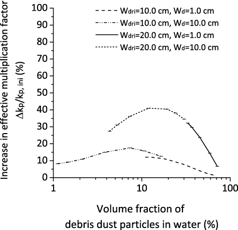
indicates the effect of pattern A of debris dust distribution on the increase in neutron multiplication. The increase in neutron multiplication, the vertical axis in the figure, was measured by the ratio of the change of effective multiplication factors to the initial effective multiplication factor of spherical resolidified fuel debris. The diameter of the drill bit, Wdri, was assumed to be 10 or 20 cm. Also, the volume fraction of debris dust particles in water was parameterized by changing the thickness and the width of the debris dust shell Wd and Ld as shown in . The highest increase in neutron multiplication was almost 41%Δkp/kp,ini for Wdri = 20 cm and Wd = 10 cm. When the diameter of the drill bit was changed from 10 to 20 cm, the highest increase in neutron multiplication was almost doubled. This is a strong reminder of the importance of carefully controlling the mass of debris dust generated by drilling resolidified fuel debris by controlling the depth of the drill hole. Also, the distributions of debris dust that maximized the increase in neutron multiplication corresponded to those with the volume fraction of debris dust particles in water close to the optimum condition.
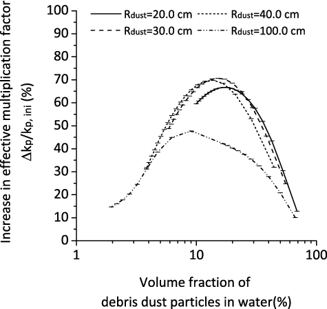
and indicate the effect of pattern B of debris dust distribution on the increase in neutron multiplication and correspond to drill bit diameters of 10 and 20 cm, respectively. The volume fraction of debris dust particles in water was parameterized by changing the radius and the height of the cylindrical space Rdust and Hdust as shown in . The highest increase in neutron multiplication is about 71%Δkp/kp,ini for Wdri = 20 cm and Rdust = 40 cm. The distribution of debris dust that caused the highest increase in neutron multiplication corresponds to Rdust = 40 cm and Hdust = 70 cm for Wdri = 20 cm and to Rdust = 30 cm and Hdust = 40 cm for Wdri = 10 cm. This results from the balance between neutron moderation controlled by volume fraction of debris dust particles in water and a fundamental neutronic feature that neutron leakage increases for horizontally flatter or longitudinally narrower distributions of debris dust.
Figure 5. Increase in neutron multiplication for pattern B of debris dust distribution corresponding to a drill diameter of 10 cm.
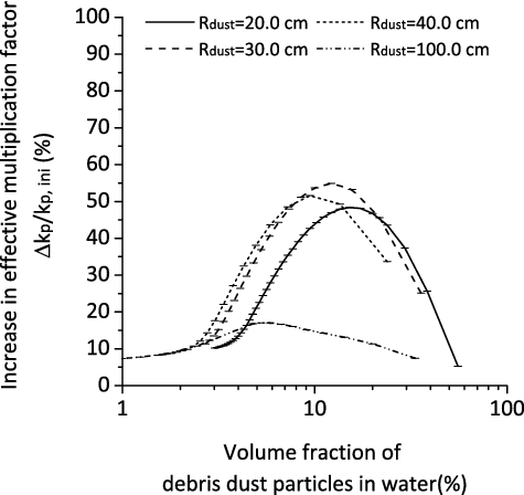
Figure 6. Increase in neutron multiplication for pattern B of debris dust distribution corresponding to a drill diameter of 20 cm.
A comparison of (pattern A) and (pattern B) indicates that neutron multiplication is maximized in drilling resolidified fuel debris if the debris dust generated by drilling is suspended separately from the resolidified fuel debris rather than if it is suspended closely around the resolidified fuel debris. Therefore, the drilling operation for resolidified fuel debris first needs to prevent debris dust from being suspended in one space as shown in in order to avoid the highest increase in neutron multiplication. A passive measure for the prevention is proposed in the next section.
3.3. Passive reduction in neutron multiplication by distribution of debris dust
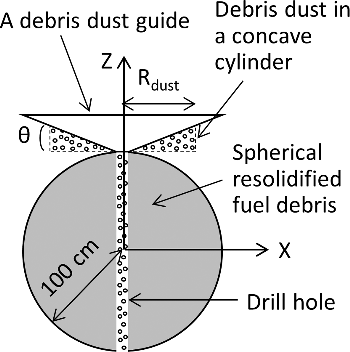
As indicated in and , a horizontally flatter distribution of debris dust shows lower increase in neutron multiplication. Therefore, an increase in neutron multiplication in drilling resolidified fuel debris will be passively limited by installing a debris dust guide at the open end of a drill hole to prevent debris dust from being suspended in one space. shows a debris dust guide in the form of an inverted frustum of a circular cone as an example. A debris dust guide distributes debris dust particles so flatly that sufficient neutron leakage limits neutron multiplication effect even if the volume fraction of the particles in water reaches the optimum condition. A debris dust guide does not include any active components, and in general it is easier to apply passive measures to the environment with a high dose rate because no additional consideration for radiation resistance is necessary. Another passive measure is to ensure a flat distribution of debris dust by an enclosure. This paper did not focus on the enclosure approach because it is expected that the leakage of debris dust from an enclosure is unavoidable.
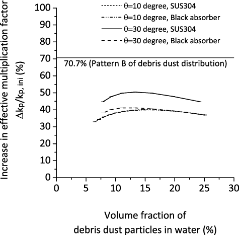
Criticality calculations were performed to confirm the effectiveness of limiting the increase in neutron multiplication by a debris dust guide in the form of an inverted frustum of a circular cone as shown in . In the calculations, the material of the debris dust guide was assumed to be SUS304 stainless steel or a black body (a perfect absorber). The upper diameter of the debris dust guide was assumed to be 140 cm as an example and the lower diameter was assumed to be equivalent to the diameter of a drill hole. Also, the guide angle θ was assigned as 10° or 30°. All of the debris dust generated from a drill hole with the diameter of 20 cm and the depth of 200 cm was assumed to be randomly suspended in the drill hole and in a concave cylinder between the debris dust guide and spherical resolidified fuel debris as shown in . The radius of the concave cylinder Rdust was parameterized to find the optimum volume fraction of debris dust particles in water that causes the highest increase in neutron multiplication.
shows that the debris dust guide effectively limits the increase in neutron multiplication. The highest increase in neutron multiplication for the guide angle of 10° was 40.1%Δkp/kp,ini for SUS304 stainless steel and 39.9%Δkp/kp,ini for a black body. These indicates that the highest increase in neutron multiplication for pattern B of debris dust distribution (i.e. 70.7%Δkp/kp,ini) is suppressed by almost 57% (40.1/70.7 × 100) if the debris dust guide is applied. Also, there was little discrepancy in neutron multiplication between SUS304 stainless steel and black body. This indicates that the 10° guide angle allowed a flat distribution of the debris dust with sufficient neutron leakage so that any discrepancy due to material selection became negligible.
To examine the effectiveness of the debris dust guide for resolidified fuel debris with a higher initial neutron multiplication factor, a sphere of resolidified fuel debris with keff of 0.982 was selected without changing the radius of 100 cm. The composition of the fuel debris was changed to a homogeneous mixture of uranium dioxide and water and the volume fraction of water in the spherical debris was set to 16%. compares the effectiveness of the debris dust guide between different initial neutron multiplication factors of resolidified fuel debris. For easy comparison, the diameter of the drill hole was fixed to 20 cm. For the fuel debris consisting of the homogeneous mixture of uranium dioxide and water, the highest increase in neutron multiplication was 33.8%Δkp/kp,ini for a cylindrical distribution of debris dust and was 13.3%Δkp/kp,ini if the debris dust guide was applied. These results indicate that the debris dust guide suppresses neutron multiplication effect of debris dust by almost 39% (13.3/33.8 × 100). shows the decreases in keff resulted from the use of debris dust guide for direct comparison between the two cases. The decrease in keff for the fuel debris with a higher initial keff is smaller than that for the fuel debris with a lower initial keff. This is attributed to the increased contribution of the resolidified fuel debris with a higher initial keff to neutron multiplication effect of the system. The increased contribution originates in two factors. One is the increase in neutron multiplication effect of the resolidified fuel debris itself. The other is the decrease in the mass of debris dust suspended in water. This is because average mass density of the resolidified fuel debris is lowered by mixing water in the debris. Therefore, it is concluded that the use of a debris dust guide is effective for passively limiting the increase in neutron multiplication by debris dust in vertically drilling resolidified fuel debris as long as debris dust suspended in water is dominant in neutron multiplication effect of the system.
Table 2. Comparison of the effectiveness of the debris dust guide.
In this study, a debris dust guide in the form of an inverted frustum of a circular cone as shown in was selected for a calculation purpose that the volume fraction of debris dust particles in water easily became between 10% and 20%, where neutron moderation is the optimum. However, a debris dust guide in the form of more flattened geometry would be more effective to limit the increase in neutron multiplication and to prevent local recriticality concurrently with careful control of the mass of debris dust in the actual drilling operation at Fukushima Daiichi nuclear power station. The physics and ideas behind all calculations in this paper should be applicable to other defueling technologies such as laser cutting and plasma cutting as long as debris dust is generated and is suspended in water.
4. Conclusion
First, this paper conservatively analyzed the neutron multiplication by debris dust generated by drilling resolidified fuel debris and suspended in water, assuming no vacuuming of debris dust and no use of borated water or active components. It was confirmed that neutron multiplication is higher if debris dust is suspended separately from the resolidified fuel debris rather than if it is suspended closely around the resolidified fuel debris. Also, it was strongly reminded that it is important to carefully control the mass of the debris dust generated by drilling resolidified fuel debris by controlling the depth of the drill hole.
Second, this paper confirmed that a debris dust guide to be installed at the open end of the drill hole effectively and passively limited the increase in neutron multiplication in drilling resolidified fuel debris. This is because a debris dust guide distributes debris dust particles so flatly that sufficient neutron leakage limits neutron multiplication effect even if the volume fraction of the particles in water reaches the optimum condition. In the actual defueling operation for resolidified fuel debris at Fukushima Daiichi nuclear power station, the use of a flatter debris dust guide will be more effective for limiting the increase in neutron multiplication as a defense-in-depth measure in addition to careful control of the mass of debris dust, vacuuming debris dust in parallel with defueling activities, and continuous circulation of borated water in the primary containment vessel. The physics and ideas behind all calculation in this paper should be applicable to other defueling technologies such as laser cutting and plasma cutting as long as debris dust is generated and is suspended in water.
Disclosure statement
No potential conflict of interest was reported by the authors.
References
- Inter-ministerial council for contaminated water and decommissioning issues. Mid- and long-term roadmap towards the decommissioning of TEPCO's Fukushima Daiichi Nuclear Power Station. Tokyo (Japan): Ministry of Economy, Trade and Industry; June 12, 2015.
- Rodabaugh JM, Cowser DK. Three Mile Island Unit 2 core region defueling. Nucl Technol. 1989 Dec; 87(4):1112–1116.
- Smith MD. Use of deep-bed filtration technology in the cleanup of Three Mile Island Unit 2. Nucl Technol. 1989;87(4):824–836.
- Muramatsu T, Yamada T, Hanari T, et al. Research on removal technologies of fuel debris and in-vessel structures using Laser light (I) – Research plan and research activities on FY2012. Japan: Japan Atomic Energy Agency; 2013, JAEA-Research 2013-024. Japanese.
- Tsuchiya A, Kondo T, Maruyama H, et al. Criticality calculation of fuel debris in Fukushima Daiichi nuclear power station. Proceedings of the International Conference on Physics of Reactors (PHYSOR 2014); 2014 Sep 28–Oct 3; Kyoto, Japan.
- Takaki N, Matsumoto T, Ishijima Z, et al. Post-accident defueling procedure and its criticality safety evaluation of the fukushima-daiichi nuclear power plants. Proceedings of the International Conference on Physics of Reactors(PHYSOR 2014); 2014 Sep 28–Oct 3; Kyoto, Japan.
- Kirkland HW, Queen SP, Shearer PM. TMI-2: drilling operations to break up resolidified core materials. Trans Am Nucl Soc. 1987;54:83.
- Nagaya Y, Okumura K, Mori T, et al. MVP/GMVP II: General purpose Monte Carlo codes for neutron and photon transport calculations based on continuous energy and multigroup methods. Tokai-mura (Japan): Japan Atomic Energy Agency; 2005, JAERI 1348.
- Shibata K, Iwamoto O, Nakagawa T, et al. JENDL-4.0: a new library for nuclear science and engineering. J Nucl Sci Technol. 2011; 48(1):1–30.

