
 ?Mathematical formulae have been encoded as MathML and are displayed in this HTML version using MathJax in order to improve their display. Uncheck the box to turn MathJax off. This feature requires Javascript. Click on a formula to zoom.
ABSTRACT
Facility design of nuclear power plant (NPP) for a sabotage protection is investigated and an effect of the design change for damage control on reduction of sabotage risk is shown using the vital area identification methodology. In a sabotage incident, it is not straightforward to identify the most credible scenario for NPP. However, the loss of offsite power leading to the station blackout is assumed to be a typical example for further evaluation. In this study, the vulnerability of vital area is considered in terms of the accessibility, the distribution of vital equipment, and the adversary's interference. As seen in the past report, the built-in measures for damage control are important in case of the existence of adversary's interference until neutralization. It is confirmed that not only the physical protection system, but also the facility design on structures, systems, and components play an important role in the effective and efficient sabotage protection. To reduce any vulnerability in the design of NPP, it is very important to introduce a security by design approach in an initial stage of the NPP construction while considering the interface between safety and security.
1. Introduction
When the severe accident occurred at the Fukushima Daiichi nuclear power plant (NPP) in March 2011, a potential threat leading to a similar crisis by a sabotage attack to NPP was recognized by the world and it was pointed out that Japan could not introduce the security preparedness deployed in the United States and other European countries after the 9.11 in 2001 [Citation1]. As the countermeasures based on lessons learned from the Fukushima accident, a specialized safety facility (SSF) for aircraft attack was imposed upon the new safety regulations that were fully revised after the accident [Citation2]. The SSF has to be equipped with electric power supply, containment vessel (CV) spray pump, molten core cooling pump, water source, and emergency control room, and is to be located more than 100 meters away from the reactor building to provide a sufficient physical separation. Electric utilities have worked to meet the new requirement and to restart the operation of NPPs. Nowadays, protection measures and/or emergency preparedness against aircraft attack have been installed into the safety regulations internationally. Although the details are confidential, the countermeasures are slightly different in individual countries. Because a state has the primary responsibility for the security incident beyond a design basis threat (DBT), the countermeasures for an extreme sabotage incident such as aircraft attack should be dependent on the state's response rather than the operator's one.
Since the 9.11 attack, it is pointed out that the US security program has been more focused on a sabotage protection in addition to a material protection such as the highly enriched uranium (HEU) minimization undertaken for the past few decades [Citation3]. This movement can be seen in the amendment of the Convention on the Physical Protection of Nuclear Material (CPPNM) in 2005 and the publication of the nuclear security recommendations from the International Atomic Energy Agency (IAEA) in 2011. In the subsequent Nuclear Security Summits (NSSs), it was emphasized that preventing sabotage is one of the fundamental responsibilities of individual countries in ensuring nuclear security. Because a security incident against NPP caused by sabotage in a country would likely affect neighboring countries, international collaboration on the prevention of sabotage occurrence and sharing lessons learned with regional neighborhood are extremely important. Needless to say, sabotage protection measures include sensitive information, so that non-disclosure of confidential information to potential terrorist is indispensable. With this in mind, to deter nuclear terrorism against NPP, not only state authorities, but also other stakeholders should participate in the discussion of the sabotage protection and the development of the methodologies to explore an effective and efficient protection, and increase the awareness of the sabotage protection. The participation from different fields under the condition of the strict information management would enhance the utilization of comprehensive knowledge as in the case of building countermeasures against cybersecurity.
On the other hand, it should be noted that aircraft attack is the extreme sabotage case and there would be other sabotage scenario by armed terrorists with or without assistance of an insider. According to the social risk analysis as seen in an F–N curve, which is a plot of cumulative frequency of natural disaster versus number of fatalities, it could be argued that the likelihood of armed terrorists’ attack is larger than that of aircraft attack. The security incident is caused by malicious acts unlike a natural disaster, so that it might be questionable whether the F–N curve can be applied to the malicious incident. However, the size distribution of consequences of an attack versus the probability of that attack shows the power–law distribution [Citation4,Citation5], and the economic loss versus the probability of an attack like the F–N curve, was used with an assumption of terrorist's rational behavior, in a cost-effectiveness study of security countermeasure [Citation6]. Therefore, we should think that it is possible to assume the F–N curve characteristics in the likelihood estimation of security incident.
The NPP operator is required to use a DBT as a basis of physical protection system (PPS) to protect against radiological sabotage and the DBT is given by the state authority based on the individual country's evaluation of the threat. After receiving the DBT from the authority, the operator starts the design of the PPS that usually does not interfere with the design of the NPP. When it is found that the PPS countermeasures that affect the structures, systems, and components (SSCs) are very effective for the sabotage protection, it is not so easy to install those measures into the existing NPP because of the high-cost retrofitting. Unfortunately the incorporation of sabotage protection into an initial stage of the facility design has been rarely discussed in the domestic nuclear society compared to the US and European countries. Naturally, the design modification includes sensitive information, so that the protection information on SSCs is not allowed to disclose as the safety requirement in the design stage. However, it is necessary to discuss the concept of the design modification and investigate the effectiveness for sabotage protection for the future construction of domestic NPP as well as the export to foreign countries.
In this paper, we show that the facility design for the sabotage protection of NPP is more focused on the SSCs and not the conventional PPS. The importance of the interface between safety and security is discussed according to the various design concepts, which are physical protection, plant layout, damage control, and addition of system. Through this comparative study, the security by design approach is evaluated. After that, we investigate an effectiveness of the design change that is less feasible after the construction using vital area identification (VAI) methodologies [Citation7,Citation8]. Finally, we emphasize the importance of defense-in-depth (DiD) measures that are not only multiple physical protections, but also damage control and mitigate in a security incident, and then conclude.
2. Sabotage protection
2.1. Safety and security interface
To ensure the protection of people, society, and the environment, the NPP has been designed based on a comprehensive safety principle that has been developed over the years. Compared to the safety system, the security consideration for the NPP design has been far less developed. After the 9.11 attack in 2001, sabotage protection has raised the priority for the safe and secure operation of NPP. The sabotage protection is closely related to a rational scenario in which the adversary would attack the SSCs of NPP effectively, and it is naturally the similar way in which the operator needs to maintain the SSCs securely. This is a logical consequence, of how important the interface between safety and security is, in the sabotage protection. In the IAEA Safety Standards, No. SSR-2/1 [Citation9], the recent publication of TECDOC [Citation10] and the report by the international nuclear safety group, INSAG-24 [Citation11], there is a statement that safety and security have a common purpose, and that security measures do not compromise safety, and safety measures do not compromise security. Unfortunately, this is not a detailed guideline to reflect an actual design. Therefore, considering the fundamental principle of the interface, the design study about the synergies and conflicts of the interface needs to be investigated.
The sabotage protection by a facility design has been discussed and investigated in the United States since the 1970s. The Sandia National Laboratory (SNL) conducted a number of studies for the Nuclear Regulatory Commission (NRC). In one of the published reports [Citation12], they presented various configurations of plant design and damage control measures for providing protection against sabotage at NPP using the Standardized Nuclear Unit Power Plant System (SNUPPS) as the reference design for the baseline plant, and the impact of such measures on facility costs, operations, and safety were investigated. The damage control includes the measures which can be taken in a short time after sabotage initiation to prevent or reduce the release of radiological materials. In addition to this, the damage control activities encompass the use of existing systems in normal or alternate modes of operation. As a result of the studies, four categories of design measures were presented: hardening critical systems or locations, plant layout modifications, system design changes, and addition of systems. The design changes in the modified plant layout are shown in and the modified layout is compared to the original plant layout. is slightly modified from the reference [Citation12]. The four options for the protection were evaluated in the impact study, and the addition of an independent, hardened, decay heat removal system (DHRS) was established as a high-value medium ranking measure. Referring to this study, in order to understand the effect of the design measures, the feasibility of retrofitting and the conflict between safety and security were developed according to the four categories. This comparative study is shown in . In comparison with the physical protection design and addition of system, it is understood that the plant layout and the damage control designs are not feasible to retrofit the already-existing plant. The effectiveness of each measure on the sabotage protection is not investigated. The plant layout and the damage control should be evaluated in an initial design stage of NPP to avoid the high-cost retrofitting. The other two options, the physical protection design and the addition of system, could be used by the existing NPP to strengthen the security countermeasures. This would be one of the reasons why the SSF, which is a typical example of DHRS, was adopted in the new safety regulations in Japan.
Figure 1. The conventional design change for sabotage protection.
Table 1. Feasibility of retrofitting and interface between safety and security
2.2. Sabotage risk
Sabotage risk is defined by taking the product of the frequency of sabotage incidence and the magnitude of consequence. Although it is difficult to estimate the initiation frequency, the risk can be described using the conditional probability and the magnitude of consequence as follows:(1)
(1) where Rj = the risk due to sequence j leading to consequence; πj = the probability that an adversary will attempt to complete sequence j; pj = the conditional probability of success leading to consequence in sequence j and c = the magnitude of consequence.
It is possible to identify discrete levels of consequences and well-defined sets of sequences leading to the different consequences level. However, in this study only, one consequence level, core damage (CD), is considered.
For certain sabotage attacks, it is assumed that it is possible to identify well-defined sabotage sequences leading to consequence. In addition, a sequence is a cut set of a sabotage fault tree (FT) equation and does not necessarily imply a particular time order because a saboteur might attack the FT components in an intentional way.
Considering all sequence levels, the total risk, R, is expressed as follows:(2)
(2) where μ = the number of sequences leading to consequence;
= the probability of release reduction by the damage control measures; qjk = the probability of completion of the kth event in sequence j and ηj = the number of discrete events in sequence j.
As noted in EquationEquation (1)(1)
(1) , the consequence level is assumed CD, so that the probability of release reduction means an effectiveness of damage control actions after sabotage initiation leading to CD to prevent or reduce the release of radiological materials.
The four categories of measures; physical protection, damage control, plant layout design, and addition of system, provide protection against radiological sabotage. The physical protection and addition of system measures have been regulated; however, the other two measures are not fully discussed. In order to investigate the effect of damage control and plant layout design on the sabotage protection, the probability of release reduction by damage control measures, , and the probability of completion of event sequence, qjk, are investigated.
3. Effect of design change
3.1. Reference sabotage scenario
There is a discussion about how to define the most important sabotage scenario. According to the rationality, the most vulnerable scenario from the operator's point of view would be the most important one for the protection. However, there is no basis that the saboteur would choose that scenario. In addition, criminals for pleasure and suicidal terrorists do not necessarily follow the rationality, so it is generally difficult to define the most important scenario objectively. In this study, taking into account the eight accident sequences for pressurized water reactor (PWR), which were shown in the new safety regulations, it is assumed that the loss of offsite power (LOOP) is the reference scenario of the sabotage attack to investigate an effect of design change for damage control. In addition, the loss of onsite alternating current (AC) power sources leading to the station blackout (SBO) is considered because the new safety regulations require the countermeasures for SBO as lessons learned from the Fukushima accident. Based on this assumption, the sabotage trees are shown in . This includes the steam generators cooling by auxiliary feed water (AFW), the breeding steam into CV, and the loss of AC and direct current (DC) supplies. The heading of event trees (ETs) marked ‘a.’ to ‘m.’ are connected by the fault trees (FTs). For the sake of simplicity, the FTs are shown as arrow rectangles instead of showing the FT diagrams. The number of basic events and the type of support systems numbered ‘1’ to ‘10’ are shown inside each rectangle. The name of headings of the events, the type of support systems, and the measure of emergency power supply are shown in .
Figure 2. Event trees and fault trees of loss of offsite power (LOOP) and station blackout (SBO).
Table 2. The detail information list in the event sequences in
In this reference scenario, at first, the LOOP is induced by the sabotage attack, and second, the onsite EDG (emergency diesel generator), ‘b.’, is attacked. If the EDG survives and the saboteur is suppressed, the sequence is represented as steam generator (SG) cooling by AFW, ‘c.’, heat release from main steam valve, ‘d.’, addition of boron water, ‘e.’ and cooling success (CS). On the contrary, after the attack of EDG, the DC and AC power supplies, ‘c2.’ and ‘n.’ are interfered in certain time period by the saboteur, the NPP would lead to severe condition and finally fall into CD.
3.2. Design change for damage control
The damage control measures that could be of potential benefit in providing protection against sabotage were studied in the 1980s [Citation12,Citation14]. Unlike physical protection measures, damage control measures are only undertaken after sabotage actions cause loss of normal function of safe shutdown condition. Contrary to the conventional damage control in [Citation12], the use of existing systems in normal or alternate modes of operation is emphasized. To overcome the shortcomings in the conventional methods such as saboteur's interference, uncertainty of time estimate for response and repair activities, and difficulty of the damage control team concept, utilization of existing systems in alternate modes with design change is pursued [Citation13]. Twenty-seven damage control measures were proposed in [Citation14]. In this study, to investigate an effect of design change on sabotage protection, the five design changes from the 27 design changes are adopted. The five design changes are defined as follows:
| (1) | ‘Redundant set of safety valves installed on main steam lines’ Provision for an emergency decay heat removal capability by manually venting the steam generators to the atmosphere via the main condensers in the event that the main steam safety valves and the power-operated atmospheric steam dump valves are disabled by sabotage action. | ||||
| (2) | ‘Safety injection pumps cross-connected to AFW system to reestablish makeup to the steam generators’ Water supply to the steam generators using the safety injection pumps in the event that the AFW system is disabled through sabotage action. | ||||
| (3) | ‘Power restored to components in a steam turbine-driven main feed water (MFW) pump train to reestablish makeup to the steam generators via existing piping’ Utilization of a steam turbine-driven MFW pump to supply feed water to the steam generators in the event that the AFW system has been disabled by sabotage. | ||||
| (4) | ‘Diesel generator auxiliary systems modified for startup and loading without AC or DC power’ Provision for the capability to place an emergency diesel generator in operation, supplying its normal Class 1E load group, when DC power is not available to the diesel generator control system or to the diesel generator auxiliary systems. | ||||
| (5) | ‘Manual operation of safety-related systems having steam turbine driven pumps’ A turbine-driven AFW train incorporating design features to permit operation following loss of AC and DC power. | ||||
Those damage control measures based on the design changes are summarized in , and added in the reference sabotage tree as in .
Table 3. Design changes for damage control [Citation11]
Figure 3. Design changes are added in the reference sabotage tree in .
The VAI methodology is applied to investigate an effect of the design changes. The VAI has been used to investigate sabotage protection of NPP in various countries and to identify the target sets for the regulatory requirements in the US [Citation15–20]. In order to develop the location fault tree (LFT) [Citation7], the equipment in the FT is replaced by the area and/or room where the equipment is located. The target set is derived by solving the LFT in the same way as the cut set in safety analysis. As the number of target elements composed of a target set increases, it becomes difficult to cause disruption of the target set. Therefore, the number is used to estimate the degree of sabotage resistance. It should be noted that the location of vital equipment is confidential information, so that the detail of LFT is not shown in this paper.
3.3. Definition of vulnerabilities
In this paper, the vulnerability is defined as the multiplication of the degree of accessibility to vital equipment, the degree of physical distribution of vital equipment, and the degree of the possible adversary's interference. The probability of completion of event sequence, qjk, in EquationEquation (2)(2)
(2) is assumed to be dependent on the accessibility and the physical distribution. Of course, other factors may influence qjk, such as robustness of vital equipment, carrying weapons, and others. However, as a preliminary study for a sabotage protection, we used this assumption for qjk. Moreover, the probability of release reduction by damage control measures,
, is assumed to be dependent on the interference. Similarly, other factors such as the available time leading to CD of disabled equipment may influence
; however, in this study, only the interference effect is investigated on
.
The accessibility to vital area generally is dependent on the physical protection system being employed, the adversary's intrusion route, the available time before neutralization, and others. For the case study to investigate the effect of design change, it is assumed that the accessibility to the areas in the CV is 0.1, the reactor building 0.3, the auxiliary building 0.5, and outdoor is 0.9. Needless to say, the outdoor is inside the limited access area, so that illegal intrusion is very difficult. However, the relative accessibility is given as the semi-quantitative scale in the consideration of the facility design for sabotage protection. The distributed equipment such as piping and cabling is defined as 0.9 to express the degree of physical distribution, and other concentrated equipment as 0.5. While the concentrated equipment would be relatively easy to protect, the sabotage action at one place quickly leads to a loss of function of the whole distributed equipment. Finally, the adversary's interference is considered. Ideally, even after the illegal intrusion has occurred, the early detection and the quick response would succeed in the neutralization and any response actions to mitigate the damage caused by the sabotage incident would not be interfered. However, in the case of a severe incident, beyond the DBT, which may have occurred, a certain period of time would be necessary until the neutralization of the adversary from the intrusion and the adversary's resistance would interfere with the operator's response as well as the response force. Therefore, the operator's action would have to be suspended until the completion of neutralization and the elapsed time would make worse the condition of damaged system. The degrees of likelihood of interference are given as 0.9 for electric power sources, 0.5 for water sources located outside the buildings, and other equipment as 0.1.
Those degrees and the calculated vulnerabilities for the typical areas and the representative equipment are represented in . These are preliminary values for this study. Using the defined vulnerabilities, it can be possible that an effect of the design change as damage control measures on the sabotage protection is investigated quantitatively. The vulnerability is defined as the multiplication of the three factors to represent qjk and to estimate the total risk, R, in EquationEquation (2)
(2)
(2) , and the more detailed quantification and sensitivity analysis of each factor would be desirable in a future study.
Table 4. Examples of vulnerabilities of target elements
3.4. Effect of design change
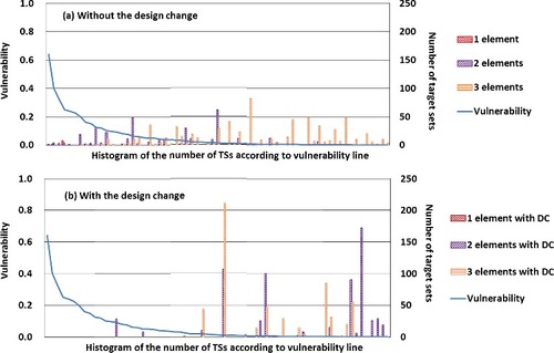
In order to evaluate an effect of the design change, the number of target sets is shown in bar charts as histograms in . The horizontal position of each bar corresponds to the vulnerability derived from the individual target element. The vulnerability is shown as the polyline in the same figure. In the reference case in (a) ‘without the design change’, the hatching bars are seen around the high vulnerability region, on the left-hand side of the figure, and 1 and 2 elements bars can be seen in those high vulnerability regions. The cumulative number of the target sets in those high vulnerability regions, that is scaled on the right-hand-side axis, is not so large compared to other low vulnerability region; however, these target sets should be very vulnerable for the sabotage protection. The number of target sets represents the sabotage scenario options. The small number means it is not easy to attack because the operator would be easy to protect. However, when the number of elements that consists of the target set decrease to 1 and 2, it means the target set is easy to attack because of a small number of elements leading to CD. This is the reason why we conclude that the reference case is valuable. On the contrary, considering the design change in (b) ‘with the design change’, the cumulative number of the target sets is large, but those vulnerabilities are very low. This does not mean that the target sets with the design change are vulnerable.
Figure 4. The number of target set (TS) and the vulnerability with and without the design change (DC).
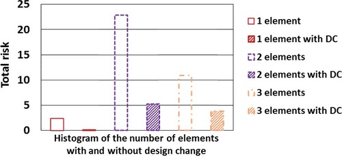
The total risk in EquationEquation (2)(2)
(2) , that is proportional to a summation of the individual target set that means the number of sequences leading to consequence, μ, and the vulnerability, is shown as a function of the number of elements in the target set with and without the design change in . The number of elements constituting the target set changes in the range of 1–3, and the effect of design change for damage control is shown. The total risk in all cases, regardless of the number of element, is reduced by considering the design change for damage control. In the most vulnerable target set, the target element placed outdoor is a major component. The accessibility and the interference of the outdoor target element are defined as 0.9. Therefore, their vulnerabilities become large and this leads to the conclusion that the outdoor element is vulnerable. It can be concluded that the built-in measures are effective and resistant compared to the emergency equipment placed outdoors. The movable equipment is flexible and resilient measure in accident management. It should be noted, however, that the equipment has to be used properly as DiD measures due to the possible adversary's interference.
Figure 5. Reduction of total risk due to the design change (DC).
4. Conclusion
The important contribution of the facility design on the sabotage protection is confirmed in this study using the VAI methodology with the vulnerability for each target element. The vulnerability is defined as the multiplication of the probability of release reduction by the damage control measures, , and the probability of completion of the kth event in sequence j, qjk, in EquationEquation (2)
(2)
(2) . The total sabotage risk in the reference scenario is compared in the two cases, with and without the damage design. The effectiveness of installment of the damage design in the security incident is shown by this quantitative study. However, it should be remarked that in more detailed study, the timeline analysis is important to evaluate the overall effectiveness of sabotage protection. The relationship between the access time of adversary and the suppression time of security authorities before the destruction of vital equipment as well as the relationship between the available time leading to CD and the prevention and mitigation time after the destruction needs to be investigated. The VAI methodology based on the Boolean algebra is not applicable to this problem, so that the transient evaluation should be explored in further study.
From this study, it is pointed out that the DiD approach is very important in the sabotage protection. After the occurrence of sabotage for vital equipment, there would be no good strategy to provide the countermeasures for the damage control in the case of continuing adversary's interference. In security DiD, the response force tries to neutralize the adversaries first, and then operators start mitigation and controlling damage initiated by the sabotage attack. However, due to the severity of consequences and delays in neutralization of the adversary, the neutralization and mitigation activities might occur concurrently [Citation10]. In this regard, the built-in measures are important as DiD measures to respond to the actions of adversaries, who upon damaging some vital equipment, could also interfere with the responding operators until the neutralization by response forces.
On the other hand, the design change has limitations under the situations in which explosives and stand-off devices are used in the incident. The hardening of containment vessel, the plant layout design, and the addition of system are still effective for the aircraft attack. It could be argued that the facility design for sabotage is dependent on what kinds and types of threat the state identifies for the NPP protection. For this reason, the DBT and beyond the DBT are very important for the state's protection strategy.
Finally, it should be noted that the publication about the protection study for sabotage attack is reviewed in terms of information management. This is concern about a balance between deterrence against and instigation to potential terrorists. We should think that raising awareness and stimulating the interface discussion have never been more important recently.
Acknowledgments
This work was supported by the Japan Atomic Energy Agency.
Disclosure statement
No potential conflict of interest was reported by the authors.
References
- Tokyo Electric Power Company. Fukushima nuclear accident summary & nuclear safety reform plan. Vol. 13. Tokyo, Japan: Tokyo Electric Power Company; 2013. Available from: http://www.tepco.co.jp/en/press/corp-com/release/2013/1235871_5130.html
- Nuclear Regulation Authority. New regulatory requirements for light-water nuclear power plant–outline. Vol. 19. Tokyo, Japan: Nuclear Regulation Authority; 2013. Available from: https://www.nsr.go.jp/data/000067212.pdf
- Bunn M, Malin MB, Roth N, et al. Preventing nuclear terrorism continuous improvement or dangerous decline? Vol. 114. Cambridge, MA: Harvard Kennedy School; 2016.
- Bohorquez JC, Gourley S, Dixon AR, et al. Common ecology quantifies human insurgency. Nature. 2009;462(17):911–914.
- Bogen KT, Jones ED. Risks of mortality and morbidity from worldwide terrorism: 1968–2004. Risk Anal. 2006;26(1):1–15.
- Winterfeldt DV, O'Sullivan TM. Should we protect commercial airplanes against surface-to-air missile attacks by terrorists? Decis Anal. 2006;3(2):63–75.
- International Atomic Energy Agency. Identification of vital areas at nuclear facilities. Nuclear security series no. 16. Vienna, Austria: International Atomic Energy Agency; 2012.
- Varnado GB, Whitehead DW. Vital Area Identification for U.S. Nuclear Regulatory Commission Nuclear Power Reactor Licensees and New Reactor Applicants. Albuquerque, NM: Sadia National Laboratory; 2008. ( SAND2008-5644).
- International Atomic Energy Agency. Safety of nuclear power plants: design. Specific safety requirements no. SSR-2/1. Vienna, Austria: International Atomic Energy Agency; 2012.
- International Atomic Energy Agency. Management of the interface between nuclear safety and security for research reactors. IAEA-TECDOC-1801. Vienna, Austria: International Atomic Energy Agency; 2016.
- International Atomic Energy Agency. The interface between safety and security at nuclear power plants. INSAG-24. Vienna, Austria: International Atomic Energy Agency; 2010.
- Ericson DM, Varnado GB. Nuclear power plant design concepts for sabotage protection. Albuquerque, NM: Sadia National Laboratory; 1981. ( NUREG/CR-1345. SAND80-0477/1).
- Suzuki M, Nishida S. Comprehensive approach for sabotage protection as safety and security interface. POS-214. In: International Conference on Nuclear Security: Commitments and Actions; 2016 Dec 5–9; Vienna, Austria.
- Lobner P. Nuclear power plant damage control measures and design changes for sabotage protection. Albuquerque, NM: Sadia National Laboratory; 1982. ( NUREG/CR-2585. SAND82-7011).
- Park CK, Jung WS, Yang JE, et al. A PSA-based vital area identification methodology development. Reliab Eng Syst Safe. 2003;32:133–140.
- Ha J, Jung WS, Park CK. The application of PSA techniques to the vital area identification of nuclear power plants. Nucl Eng Technol. 2005;37:259–264.
- Lee YH, Jung WS, Lee JH. Importance of location dependencies such as cable and pipe runs when identifying the vital areas. Nucl Eng Des. 2012;242:458–467.
- Chwasz C. Requirements for a computer code system for the development and maintenance of target sets [master's thesis]. Knoxville, TN: University of Tennessee; 2015.
- Malachova T, Vintr Z. Vital area identification –state -of-the-art. Adv Military Technol. 2015;10:81–96.
- Gopica V, Sanyasi Rao VVS, Ghosh AK, et al. PSA based vulnerability and protectability analysis for NPPs. Ann Nucl Energy. 2012;50:232–237.