
 ?Mathematical formulae have been encoded as MathML and are displayed in this HTML version using MathJax in order to improve their display. Uncheck the box to turn MathJax off. This feature requires Javascript. Click on a formula to zoom.
ABSTRACT
A method of designing and evaluating HMI (human–machine interaction) is proposed for the design in supervisory control of fully digitalized I&C (instrumentation and control) and digitalized human–machine interface system, which is a large-scale complex system in the NPPs (nuclear power plants). The proposed method consists of plant accident scenario simulation, knowledge base establishment, and interaction simulation. The plant accident scenario simulation is to analyze the plant behavior and system sequences under the predefined conditions; the knowledge base is modeled based on the simulation results as human and machine roles; and the interaction simulation is to simulate the interactions such as between operator and plant, operator and technical advisor. The proposed method utilizes the object-oriented software named plant DiD (defense-in-depth) risk monitor with the combination of accident simulation by an advanced nuclear safety analysis code such as RELAP5/MOD4. The practical developments for the details are demonstrated using an example practice for the SBLOCA (small break loss of coolant accident) case of passive safety PWR (pressurized water reactor) AP1000.
1. Introduction
Human–machine interaction (HMI), which is recognized as essential for process safety, quality, and efficiency, comprises all aspects of interaction and communication between human (users) and the machines via human–machine interfaces. The term ‘machine’ indicates any kind of designed system such as automation which is denoted as the supervision and control system [Citation1]. Automation achieves the better goals such as greater safety, much better-quality control, cost saving as well as liberating human from laborious work. However, automation leads to the reduction of operator system awareness and manual skills while increasing monitoring workload [Citation2]. Although the current design, especially for the nuclear power plants (NPPs), employs the passive safety design which tries to exclude the human from the safety control system. However, in case of automation failure, the human factor becomes critical in the safety critical systems to cope with the accident. This is the famous argument of ‘ironies of automation’ by Bainbridge in 1980s [Citation3]. Therefore, the HMI should be effectively designed to achieve that the human harmonizes with automation to accomplish the safety and efficiency in the complex and typically large-scale systems such as NPP, aircraft control, and manufacturing plants.
HMI changes depending on the human's roles determined by the level of automation which specifies the automation degree of a control system according to Endsley [Citation4] and the type of automation which is defined as acquisition, analysis, decision, and action in an automation system according to Parasuraman [Citation5]. Prevalently in the current NPPs, human operators usually play the supervisory controller role [Citation6]. The automation may become the ‘black box’ for the operators. Although, there are some efforts and improvements in automation design such as adaptive automation [Citation7,Citation8], human-centered automation [Citation9], and many researches on human factor engineering [Citation10] for HMI design, it is still difficult to anticipate all potential interactions between human and automation [Citation5]. Therefore, it is necessary to propose a method to evaluate the interactions and develop the knowledge base for HMI design.
Meanwhile, there is a firm belief in nuclear safety regulations that human error is a source of trouble and may result in accident. In order to prevent any accident caused by human error like Three Mile Island (TMI) [Citation11], the procedures are formulated, following which the operator is restricted to perform certain predetermined tasks and actions. Following the taxonomy in the ‘skill-rule-knowledge’ model [Citation12], the procedure-based plant operation is one of the rule-based human behaviors. However, a specific procedure may not be anticipated and prepared for the accident that the operator is facing. Thus, one possible solution is that the knowledge base is developed for the plant and the operator achieves the knowledge-based behavior. This solution is one of the knowledge-based human behaviors.
Therefore, the authors of this paper would like to propose an integration method which integrates the accident simulation and the knowledge base for designing and evaluating HMI for such advanced NPPs based on inherent safety concept. A passive safety PWR—AP1000 [Citation13] is considered as the concrete target of this study as AP1000 adopts many automatic safety functions to exclude human intervention. The proposed method utilizes the object-oriented software named plant DiD (defense-in-depth) risk monitor which is designed and developed by the authors [Citation14] with the combination of accident simulation by an advanced thermal hydraulic nuclear safety analysis code RELAP5/MOD4 [Citation15].
The subsequent part of the paper is organized as follows: the evaluation aspect of HMI design is given in Section 2; the proposed HMI simulation and evaluation method are presented in detail in Sections 3 and 4; a case study is presented with the example of passive safety system for AP1000 in Section 5; finally, conclusions and future work are discussed in Section 6.
2. Evaluation aspect of the human–machine interaction design
Although the aim of automation is to reduce operator workload and fatigue, improve safety, and facilitate faster and more accurate control of multiple simultaneous tasks, it may also lead to problems in the interaction between operators and automated systems [Citation2]. The operator situation awareness is one of the important aspects related to human performance. It is shown that in higher level of automation the operator may have the lower situation awareness [Citation6]. In the TMI accident, a misunderstanding of the automation caused the operators to have incorrect situation awareness. The incorrect situation awareness resulted in making wrong decisions which led to the accident. Based on the situation awareness model proposed in [Citation16], it is divided into three levels: Level 1 – perception of elements in current situation (perception); Level 2 – comprehension of current situation (comprehension); and Level 3 – projection of future status (projection).
3. Proposed evaluation method of human–machine interaction
The purpose of the authors’ study is to simulate the interactions for the design and evaluation of HMI using developed experimental tools by the integrated use of two types of computer simulations, i.e. plant accident simulation and knowledge-based information processing. As shown in , it is the framework to integrate the plant accident simulation with knowledge-based information processing for the HMI design.
Figure 1. Framework of integrating the simulation and knowledge-based information processing.
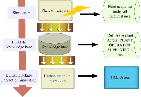
3.1. Plant simulation
The plant simulation simulates all the aspects of plant including transient and accident, which require the control of automation and the human intervention. Therefore, the plant sequences can be acquired. Besides, the designer may pay special attention to the HMI design for some specific plant transient scenarios. At the situation, the plant scenarios should be defined and simulated. The plant simulation models are not depicted in this paper while the simulation results are used to build the knowledge base.
3.2. Knowledge base
The knowledge base stores and represents the dynamics of the plant. In this paper, the knowledge base is built in the state-transition way using the software named plant DiD risk monitor in the hierarchical way. In order to design the human and automation interaction, two kinds of knowledge base should be built, i.e. plant knowledge base and human knowledge base.
The plant knowledge base consists of the plant equipments and the automations. The knowledge base of the plant equipments models the main process variables that are calculated by the simulator and connected with the knowledge base and the automation knowledge base describes the automation system task such as how and by what way the automation system will be actuated.
The human knowledge base represents the organizational configuration of operational staff and mutual communication in the main control room (MCR) of NPPs. In addition, human knowledge base models the operation following the procedures step by step such as monitoring, confirmation of the machine state, and the manual operation in case of the automation failure.
3.3. Human–machine interface design
The efficient human–machine interface design may help the operators to perform the correct operation and improve the operator performance. Therefore, a basic idea is proposed for the intelligent human–machine interface design so as not to limit the operator to a specific procedure but generate the knowledge-based procedures.
The proposed idea is a methodological framework for both design and evaluation of digital human–machine interface system by introducing the following three elements: (i) automatic diagnosis, (ii) automatic selection of operation procedure, and (iii) coordination of bi-directional communication between human (operators) and machine (automated system), with automatic processes of the above functional modules of (i) and (ii). The essence of designing and evaluating the human–machine interface composed by those three elements can be schematically depicted as shown in .
Figure 2. Basic scheme of designing and evaluation of human–machine interface.
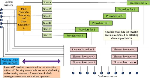
The automatic diagnosis element recognizes the plant states by monitoring the plant parameters. Then, the procedures to cope with each recognized plant state are automatically generated by the selection of the element procedures. Following the procedures, plant is operated by various actuators, while the message and parameters are displayed to the user interface. By automatic diagnosis and procedure generation, the knowledge-based procedures are created automatically case by case for every situation that operator may encounter. This paper proposes the basic scheme for intelligent human–machine interface design without detailed solutions for automatic diagnosis and automatic procedure generation.
However, the automatic diagnosis is not necessary for all plant conditions to support the operators. For example, in the boiling water reactor (BWR) when the LOCA accident happens, the procedures require the operators to recognize the plant state, then the operators manually scram the reactor to bring it to the cold stand-by state [Citation17]. Therefore, the automatic diagnosis element is necessary to support the operator in the BWRs. Whereas in the AP1000, the design requires no operator actions to mitigate the design basis accidents and the passive safety systems are actuated to bring the reactor to cold stand-by state [Citation18]. Consequently, the operator is just monitoring the plant parameters and automatic diagnosis is not required for this plant condition. So, in the case study for SBLOCA in AP1000, there is no state recognition but only the plant parameters monitoring.
4. Conducting steps of evaluating human–machine interaction
The transients and accidents are usually simulated by computer and all the process variables are calculated. However, in the plant, parameters are measured using the instrumentations. Therefore, the following steps are organized in order to practically evaluate and design the HMI for the real plant.
4.1. Scenario classification of the plant progression on the transient and accident simulation cases
In the NPPs, the HMIs are different at different plant states and during different transients and accidents. Furthermore, at different plant conditions, the operator pays different attentions for the interactions. Therefore, the scenarios should be first identified for the HMI design purpose.
Afterwards, the plant dynamic is simulated for the selected scenario. The state transitions for the machines and systems are simulated as the sequences with time. All plant process variables during the transients and accidents are calculated. The plant behavior in the selected scenario is unambiguous and the HMI can be evaluated and designed based on it. In this study, the simulation is performed using the advanced thermal hydraulic and nuclear safety analysis code RELAP5/MOD4.
4.2. Reduction of space-time co-relationship between plant-instrumented signals and the computed output of simulation analysis
In the real plant, the process variables are measured from the sensor signals using the instrumentations. The measured signals are the approximation of the process variables. However, the accident process signals are not obtained from the real plant but calculated by the simulator code. In this paper, the real plant process variables are approximated using the simulated parameters. The measured signals are approximated by coupling the simulated parameters with the sensor model.
In order to estimate the measured signals, the input and output of the sensor can be related by the first-order model as given in EquationEquation (1)(1)
(1) . Then, the sensor model with time can be obtained by the inverse Laplace transform as given in EquationEquation (2)
(2)
(2) . The sensor-measured signals by the plant I&C without error are calculated by the convolution between the simulated signals and the sensor model as given in EquationEquation (3)
(3)
(3) . Finally, the errors are estimated as random errors that follow the Gaussian distribution as given in EquationEquation (4)
(4)
(4) :
(1)
(1)
where X(s)is the input and Y(s)is the output of the sensor; k is the static gain, which determines the static response of the sensor; τ is the time constant, which determines the dynamic response of the sensor:
(2)
(2)
(3)
(3)
where Mi(t) is the measured signals without error, which is calculated from the simulated signals; f(t) is the simulated process variables:
(4)
(4)
where M(t) is the measured signals with error, which is calculated from the simulated signals; R(t) is the sensor error that is estimated by Gaussian white noise.
4.3. Hierarchical knowledge base models of the plant configuration
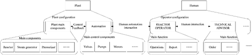
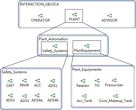
The hierarchical representation of the plant systems is to build the knowledge base for the simulated scenarios. The hierarchical representation is modeled in the plant DiD risk monitor software. Generally, there are machine and human in the plant. The top-level is the actor level in which several actors are defined to simulate the interactions such as the plant actor, advisor actor, and operator actor. The next level is the main function or sub systems for the corresponding actor. Until then the last level is the detailed machine for each system. There are different hierarchical models for different configurations of the plant. As shown in , it is an example for the hierarchical representation of the plant configuration including both the plant and human. In this example, plant main components model the plant main process variables such as primary system pressure, hot led and cold leg temperatures and automation models the safety systems in the plant. Their interactions are the control of the machine and the feedback of the machine state. The human actor shows the example operator team, which are reactor operator actor, technical advisor actor, and so on. The interactions between them are the human communications.
Figure 3. The hierarchical representation of the plant configuration including both the plant and human.
4.4. Anomaly detection from the measured signals and the logic calculation for the automated systems
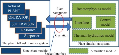
With the estimated measured signals in Section 4.2, it is possible to model the automation logic knowledge base. First, the plant simulation system is connected with the plant DiD risk monitor system using the socket interface [Citation19] as shown in . By using the socket interface, the plant DiD risk monitor system can get the measured signals from the plant simulation system as well as send the operations to the plant simulation system.
Figure 4. The connection between the plant DiD risk monitor system and the plant simulation system.
Second, plant DiD risk monitor system monitors the measured signals during simulation to detect anomaly and calculate the logic. Whenever process variables approach the limits that are programmed in the setpoints, automation will initiate the safety systems in designed sequence and corresponding alarms alert the operator. As shown in , the plant states are recognized and the procedures are generated for the plant operation. Therefore, the monitor-actuation can be designed as an event-handler. Whenever process variables approach the limits, an event is generated and corresponding handler actuates the safety systems.
4.5. Human–machine interaction simulation results
The plant DiD risk monitor software can simulate the interactions using all the inputs from the simulation and the plant knowledge base. Three main kinds of information are displayed: (i) plant machine and system status with time information; (ii) main plant process parameters; (iii) HMI results which are shown as the sequence diagram.
The results can be analyzed to design a completely new procedure for a new scenario and improve the procedure steps. Moreover, the results are displayed to support operators to know the plant situation. As a designer, by using the interaction results between human and automation, it becomes possible to find problems in the procedure and to propose effective countermeasures to improve the human factor issues. The HMIs can be evaluated in two ways:
| (1) | The tasks cannot be accomplished in the required time limitation. Normally, in an emergency procedure there is time limitation to achieve the required steps. However, if such task is completed over the limitation time during the interaction simulation, the cause should be investigated. The cause might be the potential improper task assignment, lack of people, or lack of resources. | ||||
| (2) | The simulation results are not desirable. In this case, the knowledge base is built based on the given scenario, but the result is not anticipated. For example, when it becomes core melt accident, the designer should investigate and propose the countermeasures and alternatives following which the reactor is cooled and safe. | ||||
After the design phase, the proposed system can run as the operator support system in the MCR. The plant status and the main process parameters are monitored and displayed to help the operator to know the plant situation. The HMI results in the sequence diagram can help the plant staff to achieve the optimized operation as the interaction results provide the possible operation for the scenario.
5. Case study
The target system for the case study is the passive core cooling system (PXS) in the AP1000 NPPs. It is said that AP1000 does not require any human intervention due to the adoption of inherent passive safety systems with many automatic functions [Citation18], which means that there is no need of operators in the MCR nor need of operational work. On the contrary, the operators of AP1000 have to confirm whether those safety functions work as they are planned. If something would fail the operators have to resolve the problem just in time so that the plant may not develop into dangerous state. This is the same manner as that requested in conventional NPPs, and this is the essential feature of supervisory control of automated systems.
5.1. Configuration of passive safety system
The configuration of passive safety system of AP1000 assumed in this study is illustrated in , and the SBLOCA break is 10-inch cold leg break [Citation20]. The description of the functions and the components of the PXS system are given in [Citation21]. The PXS system comprises of two core makeup tanks (CMT), passive residual heat removal system (PRHR), two accumulators (ACC), Automatic Depressurization system (ADS1-4), and in-containment refueling water storage tank (IRWST).
Figure 5. Configuration of passive safety system of AP1000 assumed in this study [Citation21,Citation22].
![Figure 5. Configuration of passive safety system of AP1000 assumed in this study [Citation21,Citation22].](/cms/asset/b6a0509a-0106-4000-9926-03052c039648/tnst_a_1417171_f0005_oc.jpg)
5.2. Scenarios for the SBLOCA simulation
Different scenarios are classified for the SBLOCA simulation. There totally eight scenarios are classified including SBLOCA with all passive safety system available and SBLOCA without actuation of some of the passive safety systems. The main results for the eight scenarios are briefly summarized in . The simulation and accident sequences for scenario 1 is simulated in [Citation13], meanwhile the simulation and accident sequences for scenario 2 are studied in [Citation23] and scenarios 5–7 are studied in [Citation24]. Scenario 4 is studied in [Citation25] while the scenarios 3 and 8 are not currently simulated. The simulated primary system pressure for scenarios 1 and 2 is shown in .
Table 1. Simulation results of the different scenarios
Figure 6. System pressure in case of SBLOCA (scenario 1 [Citation24] and scenario 2 [Citation23]).
![Figure 6. System pressure in case of SBLOCA (scenario 1 [Citation24] and scenario 2 [Citation23]).](/cms/asset/1a6a24fb-2964-43eb-9d5e-6ee5c411fd74/tnst_a_1417171_f0006_oc.jpg)
The time sequences of the safety systems with the descriptive primary system pressure trend are illustrated in . The sequences of individual subsystems in scenario 1 as shown in belong to the ‘ideal situation’ when every subsystem would work successfully as it planned in advance. That is, every sensor measuring the right signal correctly, and every alarm handling facility processes the logical judgment rightly to generate proper warning or trigger the right actuator correctly. However, if there is any failure at any step, then the behavior of the plant will become a different process than that given in .
Figure 7. Activation sequence of safety system in case of SBLOCA (scenario 1) [Citation22]..
![Figure 7. Activation sequence of safety system in case of SBLOCA (scenario 1) [Citation22]..](/cms/asset/d4e110f1-1e4d-4e27-a369-2851070c2df6/tnst_a_1417171_f0007_oc.jpg)
5.3. Measured signals calculation and connection with the model
The measured signals are calculated using the simulated signals as described in Section 4.2. Then, the measured signals are connected with the hierarchical models. All the process variables that are measured by the instrumentation and control system are presented in [Citation13] and the variables which are simulated and connected with the knowledge-based models in the case study are shown in the , in which the sensor models with parameters are depicted.
Table 2. Sensor models for the different signals
5.4. Hierarchical knowledge base of the plant scenario
Based on the scenario analysis and accident simulation results and consequences, the passive safety systems are represented in the plant DiD risk monitor software and the models for the scenario 1 are depicted here. In , it shows the top-level model of the systems. In the configuration, there are three actors as OPERATOR actor, PLANT actor, and ADVISOR actor. In the PLANT actor, it models the service of the safety systems and the main plant equipments. The plant equipments input the main process variables and the safety systems are actuated by the designed logic.
Figure 8. The top and hierarchical diagram for the passive safety systems.
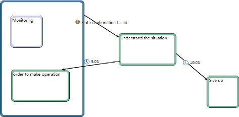
The ADVISOR actor simulates the shift technical advisor in AP1000 NPPs and the main function in model is to monitor plant and order to operator when they discover any unexpected situations as shown in . shows the model for technical advisor interacting with the operator using the plant DiD risk monitor software. The diagram shows that whenever advisor receives the ‘state confirmation failed’ event the advisor will transit to ‘understand the situation’ state. A group state is used as the two states have the same event. Normally, the supervisor is in monitoring state. But if the operator reports that the state confirmation failed, the supervisor will order the operator to make some operation and the supervisor gives up without any order to the operator after several times.
Figure 9. The process of the shift technical advisor.
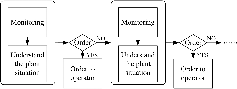
Figure 10. The detailed model for the ADVISOR actor.
The OPERATOR actor simulates the operator in the NPPs to monitor the parameters, make operation to the plant systems, confirm the status of the machines and systems, and report to the technical advisor as shown in . shows the detailed model for operator that are mainly monitoring and confirming the status of the passive safety systems in the plant DiD risk monitor software. represents the activation sequence of the safety system during SBLOCA accident. The failure of the different safety systems constitutes the different scenarios in this paper. The automation model shown in is the detailed automation sequential model for scenario 1 that all safety systems are actuated as designed.
Figure 11. The process of the OPERATOR.
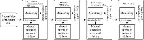
Figure 12. The detailed model for the OPERATOR actor.
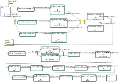
Figure 13. The process of the automation.
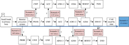
Figure 14. The detailed model for automation in PLANT actor.
5.5. The anomaly detection and logic judgment
The logic and the anomaly detections generate the internal and external events that actuate the device or operation for the system processes in the plant DiD risk monitor software. As defined in [Citation14], four types of events and their handlers can be defined and they are: (Equation1(1)
(1) ) actor external event, (Equation2
(2)
(2) ) actor internal event, (Equation3
(3)
(3) ) primary event, and (Equation4
(4)
(4) ) timer event.
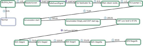
In fact, not all the actuation signals are simulated in the case study. Therefore, the events and their handlers can be modeled in two ways: one is for the actuation signals that are simulated and the other one is for the actuation signals that are not simulated. For the simulated actuation signals, they can be monitored by the plant DiD risk monitor software. Therefore, the event can be defined as external event with handler or internal event with handler. In this case, an event is generated by monitoring the process variables and the handler makes the state transition. For the actuation signals that are not simulated, the event can be defined as timer event based on the simulation sequence results such as shown in . In this case, the state transits after the time delay defined by the timer.
For example, in the ‘reactor trip’ and ‘safe guard signal’ are generated as the actor external event in the PLANT actor by monitoring the primary system pressure, which will actuate the operator to confirm the ‘SG feedwater stop’, ‘Main steam isolation’, and ‘RCS pump trip’ in the OPERATOR actor (in ). After confirmation, three internal events are generated to trigger the following process in OPERATOR actor. Whenever the anomaly is detected or the logic is triggered, some event will be generated, which will evoke the action of the human or automation.
The primary event is defined when the state becomes active or inactive. For example, the primary event can be defined to generate an event when a state becomes active and transit to the following state which handles the event.
In , the actor internal event and timer event are defined for the state transition. For example, the primary system pressure is monitored and an actor internal event named ‘RS@this’ is generated when the pressure is lower than the defined limit. Following the internal event, the state transits to the following modeled states. At the same time, some state is triggered after the certain period of time delay as the timers defined in . These timers are calculated from the simulated sequences of the accident scenario in .
5.6. Human–machine interaction simulation results
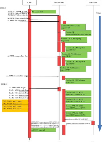
The HMI simulation results for scenario 1 are shown in . In this interaction simulation, there are three actors named as PLANT, OPERATOR, and ADVISOR. In the PLANT actor, the main information is the alarms to the operator and the statuses of the safety systems while OPERATOR actors mainly confirm results of the safety systems (confirm OK or failed). The ADS stage 1 failure is simulated as a hypothetical failure that the valves are stuck-closed. The OPERATOR actor reports the ADS stage 1 failure to the ADVISOR actor; then, the ADVISOR actor orders the OPERATOR actor to make manual operation; finally, the ADS stage 1 is opened successfully. It is assumed that the ADS stage 1 is timely opened and thus the scenario goes back to the scenario 1.
Figure 15. Display of human–machine interaction by plant DiD risk monitor.
From the interaction simulation results, it can be known that in this scenario the tasks are accomplished within the required time limitation and the results following the procedure are desirable. Therefore, the procedure for this scenario is evaluated. Then, the procedure can be designed as the rules that the operators would follow.
5.7. Plant DiD risk monitor functions as the operator support system
After the procedure is designed and improved based on the HMI simulation results, the plant DiD risk monitor can support the operator in the MCR when it is connected with the real plant digital I&C system. However, in the following parts the functions and results are still demonstrated when the plant DiD risk monitor is connected with the plant simulation system. The main function is to help the operator to make the correct situation awareness of the plant and achieve the optimal plant operation.
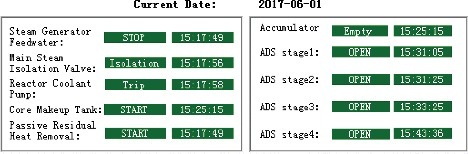
The status of each safety system is monitored and displayed for the operators as an example shown in which is an example display at a point of time during the interaction simulation. The status display indicates whether the system is working as per its design. If the system works as the design it shows the status in the dark green background with white color, otherwise it shows the current status in the dark background with red color. The time information which indicates the safety system actuation time is displayed to support the operator situation awareness. If the safety system status is not as per intended design and not actuated to alleviate the accident, there is no time information displayed. For example, CMT is stopped by the accumulator injection. The ‘STOP’ status is not the intended status, so the time information is displayed as empty. shows the safety systems status for the scenario 1 in which all the safety systems are actuated as the designed solution and the plant is successfully settled to cold shutdown state.
Figure 16. Safety system status example display.
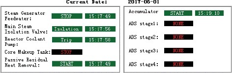
Figure 17. Safety system status for scenario 1.
Furthermore, the parameters in the scenario 1 are shown to the operational staffs as . The trends of the parameters are real-time displayed and it can help the operational staffs to make the correct situation awareness and make the prompt and proper operation. Following parameters display, the operator can observe occurrence of the transient or accident from the trend of the important process variables. By combination of the information in , the operator can recognize the accident and the transient of the plant and make the correct action to cope with the accident.
Figure 18. Main parameters trends.
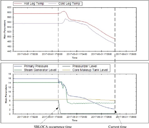
The parameter display is designed as the ‘intelligent’ display which automatically collects the most concerned process variables for the simulated scenarios. With the intelligent design, the operational staffs will quickly monitor the key parameters which are the crucial variables for the scenario.
The HMI result can help the operator to enhance the situation awareness of the plant. For example, in the result, it is shown that the valves belonging to the ADS stage-1 are stuck-closed. After receiving this message, the shift technical advisor immediately makes an order to the operator. Then, the valves are opened manually. In the proposed method, the system status monitor and display can help the operator to make the correct situation awareness in Level 2.
The monitoring workload for the NPP operator is another critical problem. For example, the operators are inundated with the large amount of alarms when the accidents occur. In the proposed frame work, the HMI results can help the operator to make the correct situation awareness in Level 1 and monitor the plant to relief the monitoring workload.
The ultimate target is to design the optimal human operation in Level3 to avoid and relieve the plant accident based on the safety system status information and the important parameter trends. However, further research needs to realize the intelligent HMI and human–machine interface design.
6. Conclusion and discussion
In order to strengthen NPP safety, many persons who believe that human may be the source of trouble in plant operations during accidents and transients have been claiming to employ more features of inherent passive safety and use of fully automatic control, in order to exclude human elements from the safety control system. However, it always remains the paradox of supervisory control that human has to cope with difficult situation when fully automated system fails to work.
In this study, a method for designing and evaluating the digital HMI was proposed for the support of plant operators’ supervisory control of fully automated large-scale complex NPPs. The proposed method consists of plant scenario simulation, knowledge base establishment, and interaction simulation. Furthermore, the proposed method utilizes plant DiD risk monitor software, which is used to make the plant knowledge base, with the combination of accident simulation by an advanced nuclear safety analysis code. The details of the proposed HMI design and evaluation method are demonstrated by an example of SBLOCA case in AP1000 (passive safety PWR). In the example, the passive core cooling system is studied, which is the most important part for the plant safety. Totally eight scenarios are classified for the example system study although two of them are not simulated. Three kinds of information are shown to support the human operation, i.e. (Equation1(1)
(1) ) plant system status, (Equation2
(2)
(2) ) real–time plant process parameters, and (Equation3
(3)
(3) ) human interaction results. The originality of this paper comparing with the authors’ previous work mainly lies in the following: (i) this paper proposes the framework for the designer used in the design phase as well as the operator for decision-making support; (ii) different plant scenarios are analyzed and modeled; (iii) different displays are designed and developed for the designer and the operator; (iv) the HMI results are designed as the interaction analyzer in the sequence diagrams, from which it is easier to analyze the HMIs.
However, future research needs to further explore the efficiency and flexibility of the proposed method for the real plant HMI design. Numerous simulations are required to build the intelligent knowledge base for both the HMI and human–machine interface design. During the plant design, some specific simulations are calculated to demonstrate the safety of the plant, whereas they are not enough for the intelligent knowledge base design. Then, the procedure should be developed for the proper simulations and the intelligent knowledge base design. The knowledge base should be flexible so as to cope with the similar scenarios. For example, the knowledge base models may be valid for different sizes of break or different places of break. Therefore, further research is required to make the proposed method to be efficient and flexible.
In the meantime, it needs further research on the integration with the MCR design as an operator support system to help the operators to make the situation awareness and relieve the workload of monitoring the plant. The integration issues with MCR include how to design the display for the operator and technical advisor; the same or different displays are to be designed for operator and technical advisor; how to design the intelligent parameter collection and display; how to design the panels to integrate the supported displays, etc. Furthermore, the automatic diagnosis and procedure generation for the intelligent human–machine interface design needs further research to find the feasible method and its integration in the operator support system.
Nevertheless, the proposed method is a possible solution for the knowledge-based intelligent HMI design and human–machine interface design. However, further researches are requisite for the real plant design and application.
Disclosure statement
No potential conflict of interest was reported by the authors.
References
- Johannsen G. Human machine interaction. Control systems, robotics, and automation. Oxford: Encyclopedia of Life Support Systems (EOLSS) Publishers; 2009.
- Singh II, Molly R, Parasuraman R. Automation-induced monitoring inefficiency: role of display location. Int J Hum Comput Stud. 1997;46:17–30.
- Bainbridge L. The ironies of automation. Psychol Bull Br Psychol Soc. 1988;3:107–108.
- Endsley MR, Kaber DB. Level of automation effects on performance, situation awareness and workload in a dynamic control task. Ergonomics. 1999;42:462–492.
- Parasuraman R, Sheridan TB, Wickens CD. A model for types and levels of human interaction with automation. IEEE Trans Syst Man Cybern. 2000;30:286–297.
- Lin CJ, Yenn TC, Yang CW. Automation design in advanced control rooms of the modernized nuclear power plants. Saf Sci. 2010;48:63–71.
- Sheridan TB. Adaptive automation, level of automation, allocation authority, supervisory control, and adaptive control: distinctions and modes of adaptation. IEEE Trans Syst Man Cybern. 2011;41:662–667.
- Jou YT, Yenn TC, Yang LC. Investigation of automation deployment in the main control room of nuclear power plants by using adaptive automation. Hum Factors Ergon Manuf Serv Ind. 2011;21:350–360.
- Goodrich MA. Boer ER, model-based human-centered task automation: a case study in ACC system design. IEEE Trans Syst Man Cybern. 2003;33:325–336.
- Carvalho PVR, Santos IL, Gomes JO, et al. Human factors approach for evaluation and redesign of human-system interfaces of a nuclear power plant simulator. Displays. 2008;29:273–284.
- Schmitt K. Automations influence on nuclear power plants: a look at three accidents and how automation played a role. Work. 2012;41:4545–4551.
- Lin CJ, Yenn TC, Yang CW. Optimizing human-system interface automation design based on a skill-rule-knowledge framework. Nucl Eng Des. 2010;240:1897–1905.
- Nuclear Regulatory Commission. Westinghouse AP1000 design control document rev. 19. Washington, DC: US Nuclear Regulatory Commission; 2011. Available from: https://www.nrc.gov/docs/ML1117/ML11171A500.html
- Ma ZG, Yoshikawa H, Nakagawa T, et al. Knowledge-based software design for defense-in-depth risk monitor system and application for AP1000. J Nucl Sci Technol. 2017;54:552–568.
- Fletcher CD, Schultz RR. RELAP5/MOD4 code manual volume V: user's guidelines. Washington, DC: Nuclear Regulatory Commission. 1995; NUREG/CR-5535, INEL-95/0174.
- Endsley MR. Toward a theory of situation awareness in dynamic systems. Hum Factors.1995;37:32–64.
- Yoshikawa H, Lind M, Matsuoka T, et al. A new functional modeling framework of risk monitor system. Nucl Saf Simul. 2013;4:192–202.
- Yan GH, Ye C. Passive Safety Systems of Advanced Nuclear Power Plant: AP1000. Proceedings of the 18th International Conference on Nuclear Engineering, May 17-21; 2010, Xi'an, China
- IEEE Std. 1003.1-2008 standard for information technology-portable operating system interface (POSIX(R)). New York, NY: Institute of Electrical and Electronics Engineers; 2008.
- Yang J, Wang W, Qiu S, et al. Simulation and analysis on 10-in. cold leg small break LOCA for AP1000. Ann Nucl Energy. 2012;46:81–89.
- Muhammad H, Yoshikawa H, Yang M. Addressing the fundamental issues in reliability evaluation of passive safety of AP1000 for a comparison with active safety of PWR. Nucl Saf Simul. 2013;4:147–159.
- Muhammad H, Yoshikawa H, Matsuoka T, et al. Quantitative dynamic reliability evaluation of AP1000 passive safety systems by using FMEA and GO-FLOW methodology. J Nucl Sci Technol. 2014;51:526–542.
- Nawaz A, Yoshikawa H, Yang M, et al. Comparative analysis of AP1000 reactor during SBLOCA with and without reactor SCRAM using RELAP5 MOD4. In: Proceedings of the 8th International Symposium on Symbiotic Nuclear Power Systems for 21st Century; 2016 Sep. 26–28; Chengdu, China.
- Hussain A, Nawaz A. The investigation of nonavailability of passive safety systems effects on small break LOCA sequence in AP1000 using RELAP5 MOD 4.0. Sci Technol Nucl Install. 2016;2016:1–11.
- Lin ZK. Model development of AP1000 NPP SB-LOCA and associated application with REALP5 [doctoral thesis]. Shanghai: Shanghai Jiao Tong University; 2012. Chinese.
- Hashemian HM. Measurement of dynamic temperatures and pressures in nuclear power plants [doctoral thesis]. Ontario: The University of Western Ontario; 2011.
- Turkcan E, Ciftcioglu O, Hagen TH. Surveillance and fault diagnosis for power plants in the Netherlands: operational experience. Vienna: International Atomic Energy Agency; 1998.