
 ?Mathematical formulae have been encoded as MathML and are displayed in this HTML version using MathJax in order to improve their display. Uncheck the box to turn MathJax off. This feature requires Javascript. Click on a formula to zoom.
ABSTRACT
A coated fuel cladding is one of the promising accident tolerant fuel (ATF) cladding concepts to enhance the fuel safety for accident conditions. In this study, a new analytical model called Fuel Rod and Cladding Analysis Subcode-Coated Cladding (FRACAS-CT), used to evaluate the mechanical behaviors of the ATF cladding, has been developed employing both thick-walled theory and some methodologies of the FRACAS. Based on the methodology of FRACAS, two different regimes of pellet-cladding mechanical interactions according to the gap status were considered as follows: one is an open-gap regime, and the other is a closed-gap regime. FRACAS-CT was developed within a limited scope of an elastic solution under the assumption of the prescribed creep, irradiation growth, and thermal deformation. To verify the FRACAS-CT model, an equivalent finite element (FE) model was proposed, and the mechanical behaviors of FRACAS-CT were compared with those of the equivalent FE model. As a result, it was determined that the stress results of FRACAS-CT are highly consistent with those of the equivalent FE model. Furthermore, FRACAS-CT was implemented into the FRAPCON4.0P1 code system to evaluate the mechanical behaviors of the ATF cladding using in-reactor conditions.
1. Introduction
After the Fukushima accident, to enhance the fuel safety under accident conditions, an accident tolerant fuel (ATF) was developed. The Korea Atomic Energy Research Institute has developed various kinds of ATF cladding [Citation1]. One of the promising concepts of ATF cladding is a coated-cladding, which is fabricated through surface modifications of conventional Zr-based alloy with a corrosion-resistant alloy. It was shown that such cladding has superior oxidation/corrosion resistance when compared with conventional Zr-based cladding [Citation2].
A fuel performance code system such as FRAPCON and FRAPTRAN is a traditional method to evaluate the performance of fuel cladding under reactor conditions because of its computational efficiency [Citation3,Citation4]. However, the current code system is modeled as a monolayer cladding, which indicates that the performance evaluation of ATF cladding is difficult to achieve through the current code system because the ATF cladding has multiple layers. Although LIFE-II code system divided a clad rod consisting of one material into multi-section to describe radial temperature gradient of the clad, it cannot apply different mechanical properties for each layer to calculate stresses and strains of the each layer [Citation5,Citation6]. For this reason, some analytical approaches have been proposed for a performance evaluation of ATF cladding [Citation7]. Lee developed structural model of multilayer cladding for light water reactors (LWRs) [Citation8,Citation9]. However, this model was limited to open-gap status, and was developed as independent code system with prescribed inputs such as thermomechanical properties and fuel rod internal pressure for operation conditions. Deng developed a new model of nonrigid Pellet–Clad Mechanical Interaction for ATF with monolayered SiC clads using FROBA-ROD code because rigid pellet assumption cannot be reasonable for the SiC clads [Citation10]. However, for the ‘FRAPCON’ code, researches on the development of mechanical module for the multilayered ATF cladding in consideration of contact between the pellet and cladding have not been reported yet.
In this study, an analytical model used to calculate the stresses and strains of ATF cladding was developed. In addition, the thick-walled theory and methodology of the Fuel Rod and Cladding Analysis Subcode (FRACAS) were employed to establish an analytical model. An equivalent finite element (FE) model was proposed to verify the developed model. To evaluate the mechanical behaviors of ATF cladding under in-reactor conditions, the analytical model was implemented into FRAPCON4.0P01, which is a computer code system used for the calculation of the steady-state, thermal-mechanical behavior of oxide fuel rods for high burn-up.
2. Development of analytical model
2.1 Thick-walled theory
Circular cylinder structures are usually classified into thin-walled and thick-walled types [Citation11]. For the thin-walled assumption to be valid, the wall thickness of the cylinder is thin when compared to the its radius, the thickness of which should be less than 10% of the radius. In the case of fuel cladding with a thin thickness, it is possible to apply the thin-walled theory, and in fact, the FRACAS was constructed based on the thin-walled theory for a thermomechanical analysis [Citation12]. However, the multilayer structure of ATF cladding makes it difficult to apply the thin-walled theory because the cladding thickness increases, and the material properties are not uniform based on the coating materials.
For this reason, application of the thick-walled theory is a suitable approach to the development of an analytical model of ATF cladding. Therefore, in this study, a thermomechanical model developed in Refs [Citation8,Citation9] based on the thick-walled theory was employed to establish an analytical model. Within elastic deformation, this model was based on generalized plane strain conditions in a cylindrical coordinate, and creep and irradiation-induced strains were considered in the following equations:
where u is radial displacement.
During normal operation, the zirconium cladding undergoes stress free axial elongation due to irradiation growth, which is strongly affected by fluence, cold work, texture, and irradiation temperature. Based on this fact, εirradiation,z was considered for axial strain component in EquationEquation (1)(1)
(1) . EquationEquation (1)
(1)
(1) was rearranged and substituted into the following stress equilibrium equation:
From EquationEquation (2)(2)
(2) , the radial displacement of u and stresses in the principal direction of σr, σθ, and σz of cladding were obtained through the following equations:
where the constants G and ξ are
For ATF cladding consisting of multiple layers, EquationEquation (3)(3)
(3) with the unknowns C1, C2, and ε0 can be expanded by considering two layers with different material properties as follows:
where i represents two layers.
In EquationEquation (5)(5)
(5) , a total of five unknowns, i.e. C1,1, C2,1, C1,2, C2,2, and ε0, remain, and should be calculated by applying the boundary conditions to obtain the stresses according to the radial position. Therefore, the methodology of FRACAS was employed to obtain the five boundary conditions, as described in the following section.
2.2 Methodology of FRACAS
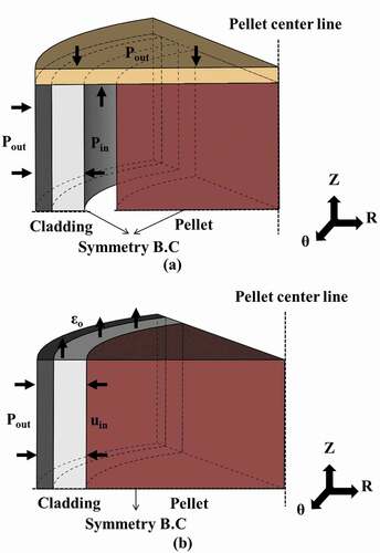
FRACAS is a computer code that performs a mechanical analysis of the fuel cladding in the FRAPCON code system. Some methodologies of FRACAS were incorporated into the thermomechanical model in Section 2.1 to describe the mechanical behaviors of the model under LWR conditions. The LWR fuel rod consists of both cladding and uranium dioxide pellets with a slight gap between them. As the operating time of the reactor increases, the pellets swell, and it makes the gap closed. According to this gap status, thermomechanical analyses carried out with FRACAS were divided into two regimes: an open-gap regime and a closed-gap regime. For the open-gap regime, the subroutine ‘cladf’ was called by FRACAS, which performs a thermomechanical analysis with the prescribed internal and external pressures of the cladding. For the closed-gap regime, the subroutine ‘couple’ was employed with the given conditions of the inner radial displacement, axial strain, and external pressure of the cladding. The internal pressure can be neglected because the behavior of the pellet is the main deformation factor of the inner side of the cladding for the closed-gap regime. The conditions for the ‘couple’ are derived by both a rigid-pellet and no-slip between the cladding and pellet assumptions, which make the deformation amount of cladding and pellet the same after the gap is closed.
These boundary conditions of ‘cladf’ and ‘couple’ were applied to the analytical model of ATF cladding, as shown in (a,b), respectively. The cladding and coating were assumed to be perfectly bonded to each other, and consequently stress and strain equilibrium equations at inner, interface, and outer radial positions of ATF cladding were employed as follows:
Figure 1. Schematics and boundary conditions of analytical model for (a) open- and (b) closed-gap regimes.
By incorporating these boundary conditions with EquationEquation (5)(5)
(5) , the unknowns of C1,1, C2,1, C1,2, C2,2, and ε0 can be obtained, and σr, σθ, and σz according to the radial position can then be calculated for open- and closed-gap regimes, respectively. The analytical models for the open- and closed-gap regimes were developed using Fortran 90.
3. Evaluation of analytical model
3.1 Development of equivalent FE model
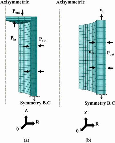
To evaluate the developed analytical models for the open-gap and closed-gap regimes in Section 2, equivalent FE models were established, as shown in (a,b), using a commercial FE software tool, ABAQUS 2016. For both open- and closed-gap regimes, the ATF cladding was modeled as an axisymmetric cylinder, and a symmetry condition was imposed to the bottom line of the FE models. The multilayer structure of the ATF cladding was modeled by dividing one body into two sections, which have different material properties from each other because of the perfectly bond assumption for the analytical model. In addition, the boundary conditions shown in (a,b), which are the external pressure, internal pressure, radial displacement, and axial strain of the cladding, were applied to the FE models equally. In the case of the open-gap model in (a), a semi-infinite long cylinder shape is designed to minimize the end-effect based on the boundary conditions of the external and internal pressures. For reliability of calculated results, mesh convergence studies was performed, and reasonable mesh size was selected as shown in .
Figure 2. Schematics and boundary conditions of equivalent finite element model for (a) open- and (b) closed-gap regimes.
3.2 Simulation of analytical and equivalent FE models
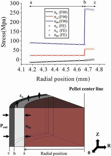
To simulate the analytical and equivalent FE models, simplified material properties for the ATF cladding were used, as shown in , respectively [Citation13,Citation14]. In addition, as shown in , the boundary conditions for the open- and closed-gap regimes were employed using modified values based on previous study for FRACAS [Citation15]. Based on these conditions, the analytical and equivalent FE models were simulated, and the stress results for the open- and closed-gap regimes according to the radial position of the ATF cladding are shown in and , respectively. Here, σrr, σzz, and σθθ represents radial, axial, and hoop stresses, and analytical and equivalent FE models are expressed as F90 and FE, respectively. As a result, it was shown that all stress distributions of the analytical and equivalent FE model were highly consistent according to the radial position. It could be that the assumption of a perfect elastic makes the two model have almost no difference. In addition, owing to the different material properties of each layer for ATF cladding, it was determined that σθθ and σzz were not continuous at the interface of the cladding and coating with the exception of σrr.
Table 1. Material properties of the analytical and equivalent finite element model
Table 2. Boundary conditions of open- and closed-gap regimes and initial environmental conditions
Figure 3. Stress results of analytical and equivalent finite element models for open-gap regime.
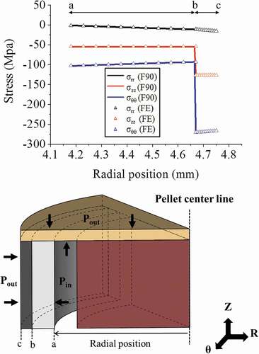
Figure 4. Stress results of analytical model and equivalent finite element model for closed-gap regime.
4. Application of analytical model to FRAPCON4.0P01
Since the FRACAS is modeled as monolayered cladding, it cannot perform the mechanical analysis for the multilayered ATF cladding. Therefore, we developed a new code called as the Fuel Rod and Cladding Analysis Subcode-Coated Cladding (FRACAS-CT) to replace the FRACAS in FRAPCON4.0P01 for the multilayered ATF cladding. The analytical models in Section 2 were developed as two subroutines for the FRACAS-CT called as ‘cladf-ct’ for the open-gap regime and ‘couple-ct’ for the closed-gap regime. As shown in , the FRACAS-CT was implemented into the FRAPCON4.0P01 with an additional subroutine ‘gapcls-ct.’
Figure 5. Process of FRACAS-CT implemented into FRAPCON4.0P01 to calculate the stresses and strains of ATF cladding.
First, the subroutine ‘cladf-ct’ for the open-gap regime is called by the FRACAS-CT because the initial gap status of the pellet and ATF cladding is open. After that, the determination of whether or not the pellet is in contact with the cladding is made by comparing the radial displacement of the pellet surface (urpellet) with the radial displacement that would occur in the cladding (urclad) due to the prescribed external (coolant) and internal (fission and fill gas) pressure. The following equation is applied to determine whether pellet-cladding contact occurs:
where δ is the as-fabricated fuel-cladding gap size.
From EquationEquation (8)(8)
(8) , gap thickness (f) can be calculated as given below:
If the thickness is positive at the current time step, the pellet–cladding gap has not closed during the current time step, and then solution has been obtained by the open-gap model of ‘cladf-ct.’ If the gap thickness is positive at the previous time step and negative at the current time step, however, the subroutine ‘gapcls-ct’ is called to calculate exact time when the gap is closed.
The ‘gapcls-ct’ is based on numerical method of modified false position method. This method finds a root to satisfy f(x) = 0 by iterative calculation as given below:
where a and b represent time steps, respectively.
shows flowchart of the subroutine gapcls-ct. For the convergence calculation, a gap thickness is calculated as a function of time, and the calculation is repeated until the gap thickness satisfies a tolerance value by increasing or decreasing time interval. This algorithm of ‘gapcls-ct’ is based on the algorithm of ‘gapcls’ of FRACAS to calculate the exact gap closure time [Citation12]. The only difference between the ‘gapcls’ and ‘gapcls-ct’ is equation for calculation of the inner radial deformation of the cladding. The ‘gapcls’ use EquationEquation (11)(11)
(11) as below because the ‘gapcls’ is based on thin-walled theory.
Figure 6. Flowchart of subroutine gapcls-ct.
where , t,
, and
are cladding midplane radius, cladding thickness, cladding midplane hoop, and radial strain, respectively. Since the analytical model, developed in this study, is based on the thick-walled theory, EquationEquation (11)
(11)
(11) cannot be applied, and then was replaced by EquationEquation (3)
(3)
(3) , which is obtained by the thick-walled theory.
Finally, after finding the exact gap closure time, the stresses and strains of the ATF cladding are calculated by ‘couple-ct’ for the closed-gap regime until final operating time.
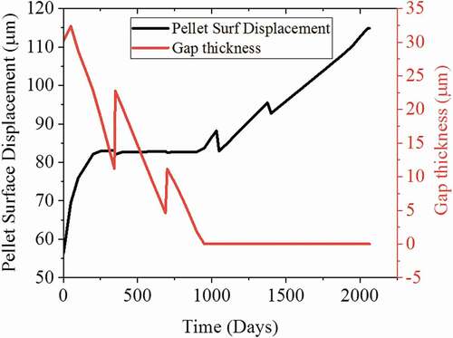
For a validation of implemented FRACAS-CT, two independent codes were employed as follows; one is the FRACAS in FRAPCON4.0P01 and the other is the FRACAS-CT in FRAPCON4.0P01. For comparison, the same material value was given for two layers of the FRACAS-CT because the FRACAS is based on the monolayered cladding. Also, since the FRACAS-CT performs only an elastic analysis, the functions for the plastic and creep behaviors in the FRACAS were set as disabled, which makes the FRACAS execute only an elastic analysis. (a) shows power history of the simulation, and (b) shows the hoop stress results of the cladding for the FRACAS and FRACAS-CT. The two results are in good agreement although they showed high values due to limitation of the elastic analysis. After 900 days, the hoop stress increased dramatically due to contact between the pellet and cladding. shows both radial pellet surface displacements into the direction of cladding and gap thickness between the pellet and cladding. Although the gap thickness was remained as zero after 900 days, local peaks of the pellet surface displacement were observed at 1000 and 1400 days, because of decrease of power, which induces decrease of thermal strain as shown in (a), and these peaks are coincident with ones of (b). From these results, it could be considered that the developed model can effectively predict the change of the mechanical behavior of the cladding tube due to deformation of the pellet in the closed-gap regime.
Figure 7. Simulation results of (a) power history and (b) hoop stress of cladding for FRACAS and FRACAS-CT.
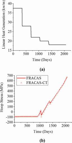
Figure 8. Simulation results of radial pellet surface displacement and gap thickness for FRACAS-CT.
5. Conclusions
In this study, an analytical model to calculate the stresses and strains of ATF cladding was developed. The thick-walled theory and methodology of FRACAS, which is a mechanical model of the FRAPCON4.0P01 code system, were employed to establish the analytical method. As a primary methodology of the analytical model, two different analysis regimes were considered according to the gap status as follows: one is for the open-gap regime, and the other is for closed-gap regime. To evaluate the analytical model, an equivalent FE model was proposed. As a comparison of the stress results between the analytical and equivalent models, the two results showed good agreement. After that, the analytical model was developed as a new module called FRACAS-CT with some subroutines. FRACAS-CT was implemented into FRAPCON 4.0P01, and an evaluation of the implementation was performed by comparing the stress results of FRACAS and FRACAS-CT under certain assumptions. However, FRACAS-CT has some limitations owing to several conservative assumptions. As further work, studies on the complex mechanical behavior of ATF cladding based on an analytical approach are needed.
Acknowledgments
This work has been carried out under the Nuclear R&D Program supported by the Ministry of Science and ICT [NRF-2017M2A8A5015064].
Disclosure statement
No potential conflict of interest was reported by the authors.
References
- Koo YH, Yang JH, Park JY, et al. KAERI’s development of LWR accident-tolerant fuel. Nucl Technol. 2014;186(2):295–304.
- Park JH, Kim HG, Park JY, et al. High temperature steam-oxidation behavior of arc ion plated Cr coatings for accident tolerant fuel claddings. Surf Coat Technol. 2015;280:256–259.
- Geelhood KJ, Luscher WG, Beyer CE, et al. FRAPCON-3.4: a computer code for the calculation of steady state thermal-mechanical behavior of oxide fuel rods for high burnup. Richland (WA): US Nuclear Regulatory Commission Office of Nuclear Regulatory Research; 2011.
- Geelhood KJ, Luscher WG, Beyer CE, et al. FRAPTRAN 1.4: a computer code for the transient analysis of oxide fuel rods. Richland (WA): Pacific Northwest National Laboratory, US Nuclear Regulatory Commission, Office of Nuclear Regulatory Research; 2011. (NUREG/CR-7023, 1).
- Jankus VZ. Fast-reactor fuel-element analysis using multiregion formulation in LIFE-II. Argonne (IL): Materials Science Division, Argonne National Laboratory; 1973.
- Jankus VZ, Weeks RW. LIFE-II - a computer analysis of fast-reactor fuel-element behavior as a function of reactor operating history. Nucl Eng Des. 1972;18(1):83–96.
- Williamson RL, Hales JD, Novascone SR, et al. Multidimensional multiphysics simulation of nuclear fuel behavior. J Nucl Mater. 2012;423(1):149–163.
- Lee Y, Kazimi MS. A structural model for multi-layered ceramic cylinders and its application to silicon carbide cladding of light water reactor fuel. J Nucl Mater. 2015;458:87–105.
- Lee Y, No HC, Lee JI. Design optimization of multi-layer silicon carbide cladding for light water reactors. Nucl Eng Des. 2017;311:213–223.
- Deng Y, Wu Y, Qiu B, et al. Development of a new Pellet-Clad Mechanical Interaction (PCMI) model and its application in ATFs. Ann Nucl Energy. 2017;104:146–156.
- Ugural AC, Fenster SK. Advanced strength and applied elasticity. Upper Saddle River (NJ): Professional Technical Reference, Pearson Education; 2003.
- Bohn MP, FRACAS: a subcode for the analysis of fuel pellet-cladding mechanical interaction. SEE CODE-9502158. Idaho Falls (ID): EG and G Idaho, Inc.,. Idaho National Engineering Lab; 1977. (No. TREE-NUREG-1028).
- Hagrman DL, Reymann GA, Mason GE A handbook of materials properties for use in the analysis of light water reactor fuel rod behavior. MATPRO Version 11 (Revision 2). Idaho Falls (ID): EG and G Idaho, Inc.; 1981. (NUREG/CR-0479).
- Chen, HY, Tsai CJ, Lu FH. The Young’s modulus of chromium nitride films. Surf Coat Technol. 2004;184(1):69–73.
- Kim HC, Yang YS, Kim DH, et al. Rigorous study of mechanical moduel in FRAPCON/FRATRAN. In: Transaction of the Korean Nuclear Society Spring meeting; 2015 May 7–8; Jeju, Korea.