 ?Mathematical formulae have been encoded as MathML and are displayed in this HTML version using MathJax in order to improve their display. Uncheck the box to turn MathJax off. This feature requires Javascript. Click on a formula to zoom.
ABSTRACT
A loosely coupled-core system was constructed in the Kyoto University Critical Assembly to study the spatial effect observed in inverse kinetics analysis of control rod reactivity worth. In a rod drop experiment, the conventional inverse kinetic method resulted in a space- and time-dependent rod worth, which depended significantly on detector position and varied remarkably with the elapse of time. In another rod worth measurement, where a control rod was continuously inserted, the similar spatial dependence could be also observed. In this study, a modal expansion approach was proposed to reduce the above spatial dependence of the measured rod worth. Applying the present approach to inverse kinetics analysis, the troublesome dependence could be solved to obtain space-independent rod worth. This approach requires only the eigenfunctions of fundamental and higher modes for an unperturbed system but makes both static and transient calculations for various perturbed systems unnecessary.
1. Introduction
In the early 1960s, an analog reactivity meter had been developed to obtain reactivity information instantaneously and continuously [Citation1,Citation2]. In the late 1980s, with the great progress in digital computer and device technology, data acquisition, analysis and other procedures had been digitalized successfully to reduce a time required for reactor physics test and to enhance a quality of the reactivity data [Citation3,Citation4]. The common principle of these analog and digital reactivity meters is to solve an inverse problem of the conventional one-point kinetics equation, where a spatial shape of neutron flux distribution is assumed to remain unchanged by any perturbations. In a large thermal power reactor and a loosely coupled-core research reactor, however, a local and large reactivity perturbation such as a insertion of control rod must significantly change the spatial shape and consequently lead to a fatal failure of this inverse kinetics analysis. Chao et al. [Citation5] proposed a dynamic rod worth measurement (DRWM) technique to overcome successfully the above difficulty in measuring a bank worth of control and shutdown rods at startup tests of many power reactor plants [Citation6,Citation7]. In the DRWM technique, the space-dependent effect is corrected based on a density-to-response conversion factor (frequently referred to as spatial factor) and another dynamic-to-static worth conversion factor (referred to as dynamic factor), whose factors are obtained by high-accuracy three-dimensional static and transient simulations carried out according to a specific rod movement. For most research reactors, the above correction procedure may require too enormous cost to employ the DRWM as a standard rod calibration method. Since the resultant reactivity worth is sensitive to the accuracy of both static and transient simulations, we can never have a valid result without carrying out a huge number of high-accuracy simulations.
The main objectives of this paper are to propose a simple modal approach for a reduction of the above spatial effect and to demonstrate experimentally the validity of the proposed method. In this method, a fundamental and a higher-harmonic contribution contained in raw time-sequence data from neutron detectors can be separated based on pre-calculated ratios of the eigenfunction of the higher mode to that of the fundamental mode at the neutron detector positions, where only the eigenfunctions of fundamental and higher modes for an unperturbed critical system are required. The present method does not require a huge number of additional static and transient simulations according to a specific rod movement and consequently has the great advantage of a large reduction of numerical cost. To achieve this goal, a loosely coupled-core system was constructed in the Kyoto University Critical Assembly (KUCA) [Citation8] and several rod worth measurements were performed to study the spatial effect observed in the inverse kinetic analysis of rod reactivity worth.
In this paper, Section 2 shows the reactor configuration and experimental setups employed, and Section 3 describes the proposed method. In Section 4, the discussion on the results is given prior to conclusions summarized in Section 5.
2. Reactor configuration and experimental setups
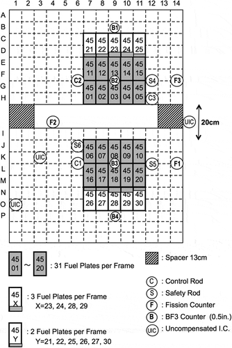
Control rod worth measurements were performed in a light-water-moderated and -reflected coupled-core system constructed in a core tank of the KUCA C-loading. The core configuration and neutron detector location are shown in . The individual cores were separated by a water gap of 20 cm and this wide gap made spatial neutron coupling much loose. This coupled-core system has a loosest spatial coupling in KUCA and the first-harmonic eigenvalue separation, which is an indicator of spatial coupling, is about 0.8$ [Citation9]. The configuration of these fuel assemblies was reported in detail by previous literatures [Citation8–Citation10]. KUCA has six control rods, where three are assigned as safety rods for reactor scram and are referred to as S4, S5, and S6, respectively. Others are rods for adjustment of reactivity and are referred to as C1, C2, and C3, respectively. In this experiment, three safety rods S4, S5, S6 and a control rod C3 were completely withdrawn. The axial positions of two control rods C1 and C2 located symmetrically were adjusted to be the same and to maintain critical state. Consequently the coupled-core system was expected to be initially symmetric to the water gap center. Under such an operation condition, two types of rod worth measurements were carried out. One was a rod drop experiment, where the control rod C2 was dropped into lower limit position to obtain a total reactivity worth of withdrawal stroke. Another was a rod insertion experiment, where the rod C2 was inserted continuously from the adjusted critical position to lower limit one to obtain a reactivity stroke curve. The above asymmetric perturbations locally inserted were expected to excite significantly a higher-harmonic mode and to result in a distortion of neutron flux distribution.
KUCA has three fission counters F1, F2, F3 assigned as reactor startup channels, and three uncompensated ionization chambers (UIC) as linear power, logarithmic power and safety channel, respectively. In addition to the above neutron detectors for reactor operation, four BF3 proportional counters (0.5ʺ dia.) were employed as experimental channels. In the present experiment, the above three fission counters and the four BF3 counters were used to measure the reactor response to a negative reactivity input induced by rod drop or continuous rod insertion. As shown in , fission counter F2 was located on a centerline of the water gap, while F1 and F3 were placed symmetrically to the centerline. Two BF3 counter B2 and B3 were placed in separate cores symmetrically to the centerline, while B1 and B4 were done in reflector region symmetrically. The nuclear instrumentation system for these fission and BF3 counters consisted of detector bias-supply, pre-amplifier, spectroscopy amplifier and discriminator modules. Finally, signal pulses from the above seven neutron counters were fed to a multi-channel scaler (MCS) to acquire time-sequence count data continuously. The channel width of the MCS was set to 1 s.
3. Theory of data analysis
In this section, first, the conventional inverse kinetics method is briefly described. Next, a general expression of the present modal approach is derived and then the general expression is reduced to apply to the present KUCA experiment.
3.1. Conventional inverse kinetics method
Assuming the zero-power and one-point kinetics model, the time-dependent neutron behavior with no neutron source can be described as:
where N(t) is the neutron density and Ck(t) the concentration of kth-group precursor. Other notations are conventional. Applying the prompt drop (jump) approximation to EquationEquation (1)(1)
(1) , the following inverse kinetics equation can be obtained:
As the above neutron density, usually, time-sequence count data or reactor-power data can be employed to determine the time-sequence reactivity . The time-dependent precursor concentration Ck(t) of delayed neutrons can be obtained by solving numerically EquationEquation (2)
(2)
(2) . For example, the application of the implicit time-integration method to the initial problem leads to:
where tj is the jth discrete time.
3.2. Derivation of general expression of present modal method
Now we assume that a reactor system is critical at t = 0, and subsequently an operation of control rod makes the system deviate from critical state and distorts neutron flux distribution. Expanding the unperturbed neutron flux and the perturbed neutron flux in a static eigenfunction series of the unperturbed critical system, the respective neutron flux can be described as:
In the above equation, the expansion is terminated in Mth-higher mode. When a J number of neutron detectors are placed, a stationary count rate of jth detector before the perturbation can be written as:
where ,
,
, and rj represent detection efficiency, effective volume, macroscopic detection cross-section and position of the detector, respectively. The transient count rate after the perturbation can be written as:
Here, we define a relative amplitude of mth mode as follows:
Substituting EquationEquation (9)(9)
(9) into EquationEquation (8)
(8)
(8) , the following equation can be obtained:
The stationary and the transient count rate of the right-hand side of the above equation are measured by a J number of neutron detectors. The ratios of the eigenfunction of higher modes to that of fundamental mode at each detector position are calculated in advance. When J is equal to M + 1, EquationEquation (10)(10)
(10) can be solved simultaneously to obtain the relative amplitude of each mode. When J is larger than M + 1, the least squares method can be employed to determine each modal amplitude. The fundamental amplitude A0(t) determined above is expected to include no contribution of higher mode. As neutron density of EquationEquations (3)
(3)
(3) and (Equation4
(4)
(4) ), the time-sequence fundamental amplitude can be employed to determine the time-sequence fundamental reactivity
.
3.3. Reduction for KUCA experiment
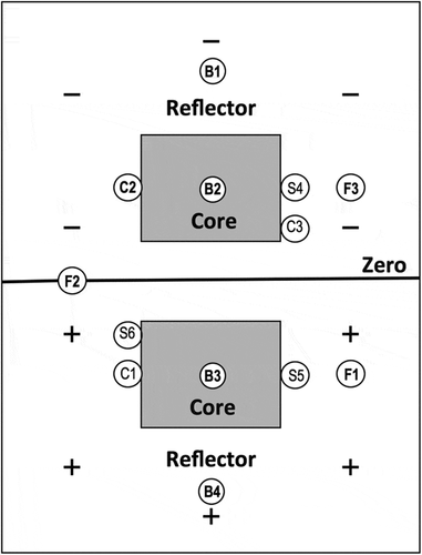
For the application to the present KUCA experiment, here the above general theory is reduced. We consider fundamental and first-higher modes (i.e., M + 1 = 2), while higher modes than second are neglected. This approximation has been successfully applied to loosely coupled-core systems [Citation11–Citation15], where an asymmetrical perturbation excites dominantly only the azimuthal first-higher mode but any disturbances slightly excite higher modes than second including any axial-higher modes. In this modal approach, we analyze the time-sequence count data from six neutron counters B1, B2, B3, B4, F1, and F3 (i.e., J = 6) mentioned in the previous section. Fission counter F2 is assigned as a reference counter for the inference of fundamental reactivity. This is because the counter F2 is placed on zero of first-higher eigenfunction as shown in and consequently the influence of the higher mode on the counter is ignorable. Under this condition, EquationEquation (10)(10)
(10) is reduced to:
where the above matrix P, the vector X and Y are denoted as:
The least squares method can be employed to determine the amplitude vector X as follows:
schematically shows zero and sign of first-higher eigenfunction in the present KUCA. The first-higher eigenfunction has an antisymmetric distribution to the centerline of water gap. As shown in this figure, the zero of the first-higher eigenfunction is located on the centerline, and the sign of the eigenfunction is positive in a half system and negative in another half system across the zero. The sign of fundamental eigenfunction is positive anywhere in the system. In loosely coupled-core reactors, the ratio of the first-higher to the fundamental eigenfunction is frequently approximated into +1 in a half system and −1 in another half system, excluding gap region [Citation13–Citation15]. Kato et al. [Citation9] calculated fundamental and first-higher eigenfunction of the present system with high-accuracy and they confirmed that the above approximation was much satisfactory under such a condition that each eigenfunction was normalized with a thermal peak value in core region. Accordingly the ratio at each position of counter B1, B2, and F3 can be set to:
On the other hand, the ratio at each position of counter B3, B4, and F1 can be set to:
Then substituting EquationEquations (16)(16)
(16) and (Equation17
(17)
(17) ) into EquationEquation (12)
(12)
(12) , the amplitude vector X can be determined from EquationEquation (15)
(15)
(15) . Inputting the time-sequence fundamental amplitude A0(t) of the vector X to EquationEquations (3)
(3)
(3) and (Equation4
(4)
(4) ) as neutron density and carrying out the inverse kinetics analysis, the time-sequence fundamental reactivity
can be determined. The delayed neutron data and the prompt-neutron generation time of the present reactor system were generated by SRAC code system [Citation16], where a three-dimensional, 19-energy-group diffusion calculation was done with JENDL-3.2 nuclear library [Citation17].
3.4. Two-detector formula for KUCA experiment
Finally we consider a reduction of a number of neutron detectors to two (J = 2) and derive a formula for a pair of detectors such as neutron counter B2 and B3. When J and M are set to 2 and 1, respectively, EquationEquation (10)(10)
(10) is reduced to:
Solving the above simultaneous equations, we obtain:
Substituting EquationEquations (16)(16)
(16) and (Equation17
(17)
(17) ) into EquationEquations (19)
(19)
(19) and (Equation20
(20)
(20) ), we obtain:
The above each equation has a simple form for fundamental and first-harmonic amplitude. From an inverse kinetics analysis of time-sequence fundamental amplitude data, we can also determine the time-sequence fundamental reactivity. The present two-detector formula is also applicable for other detector pairs of B1 and B4, F1 and F3. As an example, the result of only the pair of B2 and B3 is presented hereafter.
4. Results and discussion
4.1. Rod drop experiment
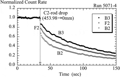
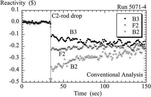
First the results of the conventional inverse kinetics analysis for the present rod drop experiment are presented. illustrates normalized time-sequence count data from a pair of counters B2 and B3, compared with those from a reference counter F2. It should be noted that the degree of prompt drop significantly differs depending on neutron counter. This feature suggests a significant spatial dependence of reactivity worth of C2 rod dropped. shows the time-sequence reactivity data obtained by the conventional inverse kinetics analysis for the rod drop experiment. From the physical viewpoint, the reactivity should remain a negative constant after the rod drop. The reactivity of the reference counter F2 has a statistical fluctuation but no varying trend over the fluctuation. On the other hand, the absolute reactivity value of the counter B2 is significantly larger than that of the counter F2 immediately after the rod drop and has a slowly decreasing trend, while that of the counter B3 is obviously smaller and has a increasing trend. The apparent dependence on space and time indicates undoubtedly a failure of the one-point kinetics model.
Figure 4. Reactivity obtained by the conventional inverse kinetics analysis for rod drop experiment.
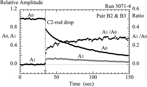
shows relative amplitude of fundamental and first-higher mode obtained from EquationEquations (21)(21)
(21) and (Equation22
(22)
(22) ). The fundamental amplitude monotonically decreases with time, while the first-higher mode is rapidly excites by the drop and decreases more slowly than the fundamental mode. The ratio of the first-higher amplitude to the fundamental one is also illustrated in this figure. As a trend, the ratio slowly increases and approaches asymptotically a constant. When the ratio is kept a constant, a spatial shape of neutron flux distribution reaches a complete equilibrium for the perturbed system.
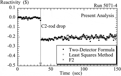
shows the time-sequence reactivity data determined by the proposed inverse kinetics analysis, compared with the result of the reference counter F2 shown in . ‘Two-Detector Formula’ of the explanatory note denotes analyzing the time-sequence fundamental amplitude data obtained by EquationEquation (21)(21)
(21) , and ‘Least Squares Method’ denotes analyzing the amplitude data done by EquationEquation (15)
(15)
(15) . The reactivity based on the least squares method has no varying trend and is consistent with that of the counter F2. The result based on the two-detector formula is also consistent but may have a trend to enlarge statistical fluctuation. Consequently we can confirm that the proposed two methods successfully reduce the spatial and temporal dependence observed in .
4.2. Continuous rod insertion experiment
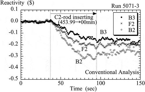
shows the time-sequence reactivity data obtained by the conventional inverse kinetics analysis for the rod insertion experiment, where the control rod C2 is continuously inserted from a critical position to another position of lower limit. The absolute reactivity value of the counter B2 more increases than that of the counter F2 with the insertion of the control rod, while that of the counter B3 less does than that of the counter F2. The difference in the reactivity among these counters is unacceptably large throughout the rod operation. From the physical viewpoint, the reactivity should remain a negative constant after the completion of the rod insertion. As a trend after the completion, however, the reactivity depending on each counter position may approach asymptotically a constant but the approach is much slow. This trend is qualitatively the same as that observed in . The above apparent spatial dependence also indicates a failure of the one-point kinetics model.
Figure 7. Reactivity obtained by the conventional inverse kinetics analysis for rod insertion experiment.
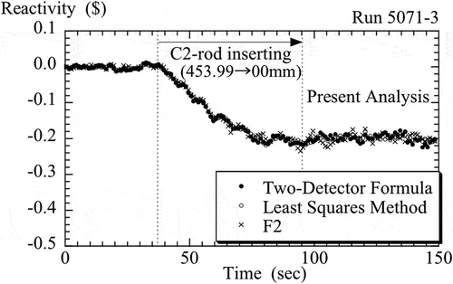
shows the time-sequence reactivity data determined by the proposed inverse kinetics analysis, compared with the result of the reference counter F2 shown in . The explanatory note of is same as that of . The reactivity based on the least squares method is consistent with that of the counter F2. The result based on the two-detector formula is also consistent. After the completion of the rod insertion, the reactivity remains a negative constant within statistical fluctuation. Consequently we can confirm that the proposed two methods successfully reduce the spatial dependence observed in .
5. Concluding remarks
A simple modal approach was proposed to reduce a spatial dependence frequently observed in inverse kinetics analysis for a large thermal power reactor and a loosely coupled-core research reactor. In a loosely coupled-core system of KUCA, two types of rod worth measurements were carried out. The application of the conventional inverse kinetics method to these measurements leads to a significant spatial dependence of the rod worth, while that of the proposed technique successfully reduced the spatial dependence. The applicability to a particular thermal reactor system of KUCA was demonstrated, however, the general expression of this technique is considered widely applicable to various thermal power and research reactors. Applying the general expression to a large thermal power reactor, not only azimuthal but also radial and axial-higher modes dominantly excited may have to be considered and on this account several detectors should be placed in respective azimuthal, radial and axial directions. The advantages of this technique are to require only the eigenfunctions of fundamental and higher modes for an unperturbed system and to make both static and transient calculations for various perturbed systems unnecessary. The detector placement on zero of a particular higher eigenfunction is useful for reducing the influence of only the mode, as shown in the present coupled-core system. However, this method has difficulty in reducing the influences of multiple spatial modes.
Acknowledgments
The present work was performed as a joint research program of the KUCA at the Institute for Integrated Radiation and Nuclear Science, Kyoto University.
Disclosure statement
No potential conflict of interest was reported by the authors.
References
- Sastre CA. The measurement of reactivity. Nucl Sci Eng. 1960;8:443–447.
- Suzuki E, Tsunoda T. A reactivity meter and its application. J Nucl Sci Technol. 1964;1:210–218.
- Shimazu Y, Nakano Y, Tahara Y, et al. Development of a compact digital reactivity meter and a reactor physics data processor. Nucl Technol. 1987;77:247–254.
- Binney SE, Bakir AJM. Design and development of a personal-computer-based reactivity meter for a research reactor. Nucl Technol. 1989;85:12–21.
- Chao YA, Chapman DM, Easter ME, et al. Methodology of the Westing-house dynamic rod worth measurement technique. Trans Am Nucl Soc. 1992;66:479–480.
- Chao YA, Chapman DM, Hill DJ, et al. Dynamic rod worth measurement. Nucl Technol. 2000;132:403–412.
- Lee EK, Shin HC, Bae SM, et al. New dynamic method to measure rod worths in zero power physics test at PWR startup. Ann Nucl Energy. 2005;32:1457–1475.
- Misawa T, Unesaki H, Pyeon CT. Nuclear reactor physics experiment. Kyoto: Kyoto University Press; 2010.
- Kato Y, Yamamoto T, Kitada T, et al. Analysis of first-harmonic eigenvalue separation experiments on KUCA coupled-core. J Nucl Sci Technol. 1998;35:216–225.
- Pyeon CH, Misawa T, Unesaki H, et al. Experiments and analyses for relationship between flux tilt in two-energy-group model and first-mode eigenvalue separation. J Nucl Sci Technol. 2004;41:171–176.
- Rydin RA, Burke JA, Moore WE, et al. Noise and transient kinetics experiments and calculations for loosely coupled cores. Nucl Sci Eng. 1971;46:179–196.
- Hashimoto K, Ohsawa T, Miki R, et al. Derivation of consistent reactivity worth and eigenvalue separation from space-dependent rod worths on the basis of modal approach. Ann Nucl Energy. 1991;18:317–325.
- Pázsit I, Dykin V. The role of the eigenvalue separation in reactor dynamics and neutron noise theory. J Nucl Sci Technol. 2018;55:484–495.
- Kobayashi K. A relation of the coupling coefficient to the eigenvalue separation in the coupled reactors theory. Ann Nucl Energy. 1998;25:189–201.
- Kawai T. Coupled reactor kinetics (II). J Nucl Sci Technol. 1965;2:285–295.
- Okumura K, Kaneko K, Tsuchihashi K. SRAC95; General purpose neutronics code system JAERI-Data/Code 96-015. Japan: Japan Atomic Energy Research Institute; 1996.
- Nakagawa T, Shibata K, Chiba S, et al. Japanese evaluated nuclear data library version 3 revision-2. JENDL-3.2. J Nucl Sci Technol. 1995;32:1259–1271.

