
 ?Mathematical formulae have been encoded as MathML and are displayed in this HTML version using MathJax in order to improve their display. Uncheck the box to turn MathJax off. This feature requires Javascript. Click on a formula to zoom.
ABSTRACT
Increased fuel assembly gap due to bowing in commercial light-water reactors (LWRs) has an impact on local pin-power distribution due to increased local moderation. In order to consider the effect of increased assembly gap without explicit consideration of increased gap width, a correction method of cross sections in the gap region is proposed. In this cross section correction method, the average chord length of gap region is preserved to capture the effect of increased gap width. The validity of the present method is confirmed by verification calculations in a single assembly and 5 × 5 assembly geometries using the GENESIS code, which is a transport code based on the method of characteristics.
1. Introduction
Fuel assemblies are bowed during burnup in a reactor core, due to various reasons such as irradiation growth of cladding materials [Citation1–Citation3]. Variation in the assembly gap dimension affects pin power peaking factor since local moderation ratio around the assembly gap region is changed [Citation1–Citation3]. If the assembly gap increases comparing to its nominal value, adjacent pin power increases due to increased local moderation. The locally increased pin power reduces thermal margin thus this effect is considered as a safety margin. Therefore, estimation of power peaking factor variation due to change of assembly gap is one of the important issues in the core safety analysis. This issue has been recognized for a long time, and some of the core design codes have the capability to evaluate the effect of assembly bowing on core characteristics [Citation4,Citation5].
Recently, high-fidelity core simulations incorporating explicit heterogeneous core geometry are becoming familiar using the planar method of characteristics (MOC) or other methods such as the Legendre polynomial Expansion of Angular Flux (LEAF) method [Citation6–Citation9].
Let us consider the modeling capability of these high-fidelity simulation codes for the assembly bowing. A bowed fuel assembly can be modeled as radially offset fuel assemblies in a core. In principle, since these simulation codes are based on the MOC or similar method, such deformation can be explicitly modeled. However, in reality, it would be cumbersome since the direct neutron path linking (DNPL, sometimes called the modular ray trace) method may be used [Citation10]. In the DNPL method, a whole geometry is covered by square, rectangular, or hexagonal frames having the identical dimension. When an offset fuel assembly protrudes its own frame, parts of two fuel assemblies coexist in the adjacent frame. Such a situation would require cumbersome input data preparation since the geometry depends on the offset dimension, which is different for every fuel assemblies in a core. Furthermore, a dedicated edit for the pin- and assembly-power distribution would be necessary since a fuel assembly would span different frames used in DNPL. Otherwise, in order to make the input data simple, the offset size of a fuel assembly may be limited [Citation11]. A fuel assembly usually bows three-dimensionally, thus the magnitude of offset varies along the axial direction. Such a situation also poses difficulties since some of the core analysis codes utilize the extruded geometry for axial direction [Citation9].
In order to address the above issue, a simplified treatment is proposed. In the present method, the nominal (non-offset) geometry is used in a calculation while the effect by offset geometry is captured by correction of cross sections at the gap water region between fuel assemblies. In a nutshell, a variation of gap water size between assemblies is converted to the variation of cross sections of the gap water region to preserve the transmission probability in the gap water region. Only cross sections in the gap water region between fuel assemblies are corrected and the cross sections inside fuel assemblies (e.g. fuel pin cell) are not corrected. PWR fuel assemblies are mainly considered in the present study, but the present method can be applied to other fuel assembly types.
In Section 2, the theory behind the present method is described. The verification results will be shown in Section 3. Finally, concluding remarks will be summarized in Section 4.
2. Theory
2.1. Relation between geometry deformation and cross section correction
The present method is inspired by the previous works [Citation12,Citation13]. In the reference [Citation12], geometry variation due to thermal expansion is incorporated by the correction of cross sections while maintaining the geometry unchanged. The reference [Citation13] utilizes the concept of ‘virtual number density’ to handle perturbation of region boundaries. These works suggest that some of the geometry variations can be treated by the correction on cross sections or number densities.
Here, the one-group neutron transport equation for MOC is considered:
where : angular flux,
: scalar flux,
: coordinate in neutron flight direction,
: total cross section,
: scattering cross section,
: production cross section,
: effective multiplication factor. Note that extension to the multi-group transport equation is easy without loss of generality.
A new coordinate is introduced as:
where is a scaling factor. By substituting EquationEquation (2)
(2)
(2) to EquationEquation (1)
(1)
(1) , EquationEquation (3)
(3)
(3) is obtained:
Now the corrected cross sections are introduced as:
Finally, the following equation is obtained:
The above formulation indicates that a variation of geometry is exactly captured by the correction of cross sections in one-dimensional slab geometry. For example, let us consider an increased gap region between fuel assemblies whose gap size is the twice of the nominal value. In order to model this gap region as the nominal size, the cross sections in this region are doubled to preserve the transmission probability at the gap region. Contrary, when the gap size between assemblies is reduced to the half of the nominal value, the cross sections of the gap region are halved to model this gap with the nominal size.
The assembly bow usually has offsets for x- and y-directions thus two-dimensional deformation should be considered in principle. However, the assembly gap is narrow and can be considered as two independent one-dimensional deformations for x- and y-directions except for the corner gap region.
In the present method, only the cross sections at the gap water region are corrected and those inside a fuel assembly (e.g., fuel pin-cell) are not corrected.
2.2. Correction in corner gap region
In the corner of assembly gap, the average chord length l calculated by l = 4V/S, where V and S are the volume and surface of the corner gap region, is considered as the ‘thickness’ of this region. For example, when the nominal dimensions of corner gap are and
, the average chord length is
. When the dimensions of gaps are increased to
and
, the average chord length becomes to
. In this case, cross sections in the increased gap region are corrected by multiplying the factor
to the cross section to model this gap region with nominal size.
In a continuous energy Monte-Carlo code or an integrated core analysis code using number densities as the input data instead of the macroscopic cross section, the number densities are multiplied by the factor instead of macroscopic cross section.
It should be noted that in the two-dimensional case, the total number of atoms in a corrected region is not preserved since the above correction just preserve the transmission probability or the optical length of a region. However, in the present application, the corner gap area is typically small thus no significant impact on the result is expected. The validity of this approximation is confirmed in the numerical calculations in the next section.
Variation of assembly gap size can be well modeled by 1- or 2D geometry. However, in principle, the present method can be directly applied to a variation in 3D geometry. In the case of 3D geometry, the chord length is calculated by its definition, i.e., l = 4V/S. The total number of atoms in a corrected region is not preserved in a 3D case as well as in a 2D case as described above.
3. Numerical results
Verification calculations are performed for the 2D single assembly geometries with offset positions and the 2D 5 × 5 multiple assemblies geometry that simulates part of a whole core. The present verification calculation aims to confirm the validity of the proposed methodology. Estimation of power peaking factor variation using actual plant data is out of the scope of this study. Comparison between the reference result considering explicit offset fuel assembly position (as is) with uncorrected cross section and the present result using the nominal (non-offset) geometry with the corrected cross section is major interest in this paper.
3.1. Single assembly geometry
The MOX-1 assembly specification in the KAIST benchmark problem [Citation14] is used in the present study since a MOX fuel has a higher sensitivity to the size of assembly gap. In the original KAIST benchmark problem, no water gap is assigned between assemblies. However, in this section, the fuel assembly is assumed to be surrounded by narrow gap water whose nominal thickness is 0.1 cm. Thus, the nominal gap between assemblies is 0.2 cm and the assembly pitch is 1.2617 + 0.1
2 = 21.62 cm. The 7-group heterogeneous macroscopic cross section provided in the benchmark problem is used. In an actual situation, effective cross sections of fuel rods adjacent to gap water depend on the thickness of gap due to the Dancoff effect. Variation of effective cross section due to increased or decreased gap size can be considered through the present method since the present method can be directly used for resonance calculations (e.g., Dancoff factor calculation, sub-group calculation, or ultra-fine group calculations). However, in the present study, the identical 7-group macroscopic cross section is used for all materials regardless of the gap size except for that of gap water. The cross sections of gap water are corrected as described in the previous section.
Combination of gap water thickness around an assembly is shown in and . When the thickness of gap water increases, assembly pitch also increases. For example, the assembly pitches for the E0.1-S0.3 case are 21.62 cm and 22.02 cm for x- and y-directions, respectively. In the present method, the nominal gap water thickness (0.1 cm) is used as is, but the cross section of gap water is corrected to preserve the average chord length (or transmission probability). In the case of E0.1-S0.3, cross sections in the south gap region is multiplied by factor 3 (= 0.3/0.1) while the nominal size (0.1 cm) is used for the north, west, south, and east gap regions.
Table 1. Thickness of gap water around a fuel assembly (unit: cm)
Figure 1. Layout of MOX fuel assembly and gap water.
The GENESIS code [Citation9] is used in the present calculation. Two-dimensional transport calculation based on MOC is used. Major calculation conditions are as follows:
Ray trace width :0.005cm
Number of azimuthal angles :64 (for
)
Number of polar angles :4 (TY, for
Convergence criteria for flux :10–4
Convergence criteria for keff :10–5
The reference and the present results are obtained by the following conditions:
Reference: Uncorrected cross sections, offset geometry
Present: Corrected cross sections, nominal geometry
The reflective boundary condition is used. Cross sections for gap water region are corrected by the method described in the theory section. In more detail, the ratio of gap size (offset/nominal) is multiplied all types of cross sections (i.e., total, production, absorption, and scattering) in the gap region.
summarizes k-infinities obtained by the reference and the present methods and their differences. The present method well captures variation of k-infinity due to increased gap width. shows perturbations of pin-power (pin-by-pin fission rate) due to increased assembly gap, which are obtained by the reference calculations. The perturbation of pin-power is calculated by:
Table 2. Variation of k-infinity due to increased gap size
Figure 2. Perturbation of pin-power distribution due to increased assembly gap size (unit:%, single assembly geometry, X indicates instrumental or guide thimbles).
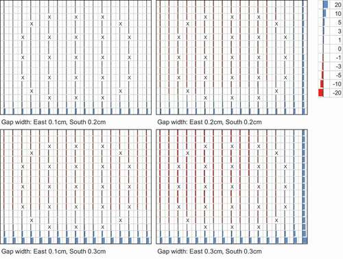
where ,
, and
are perturbation of pin-power, pin-powers in increased gap geometry, and pin-powers in nominal gap geometry. clearly shows pin power around the increased gap region becomes higher as the size of gap water increases. shows the difference of pin-powers between the reference and the present results calculated by
. and show more detail comparison of pin-power distribution. From , maximum variation of pin-powers due to variation of gap in the present calculation reaches approximately 20%. However, shows the present method reproduces the reference pin-power distribution within 0.5% difference. These results indicate that the present model using the nominal geometry and the corrected cross sections well reproduces the reference result, which is obtained by the calculation using the explicit offset geometry and uncorrected cross sections.
Figure 3. Difference of pin-by-pin fission rate obtained by the reference and the present methods (unit:%, single assembly geometry, X indicates instrumental or guide thimbles).
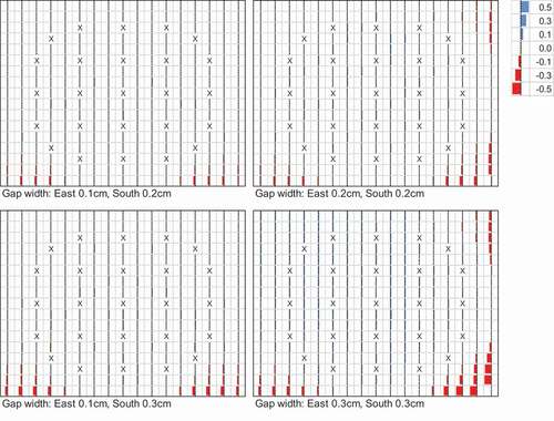
Figure 4. Comparison of pin-by-pin fission rate (Eastern boundary, from North-East corner to South-East corner).
Figure 5. Comparison of pin-by-pin fission rate (Southern boundary, from West-South corner to East-South corner).
3.2. Multiple assemblies geometry
In order to check the validity of the present method in a more realistic situation, offset fuel assemblies are modeled in a 5 × 5 assemblies geometry. The MOX-1 fuel assembly used in the previous section is also used. In this calculation, the nominal thickness of gap water around an assembly is assumed as 0.07cm. It means that the nominal gap size between assemblies is 0.07 2 = 0.14 cm and nominal assembly pitch is 1.26
17 + 0.07
2 = 21.56 cm. As shown in , the assemblies A and B are offset to the extreme left (west), i.e., the gap between A and B, and the west gap of A are set to be 0.0 cm. The assemblies C, D, and E are offset to the extreme right (east). Thus the gap between C and D, D and E, and the east gap of E are set to be 0.0 cm. The gap size between assemblies B and C is 0.7 cm (= 0.07
2
5). In order to explicitly model this offset geometry, the geometries of assemblies A, B, C, D, and E are defined independently in the reference calculation.
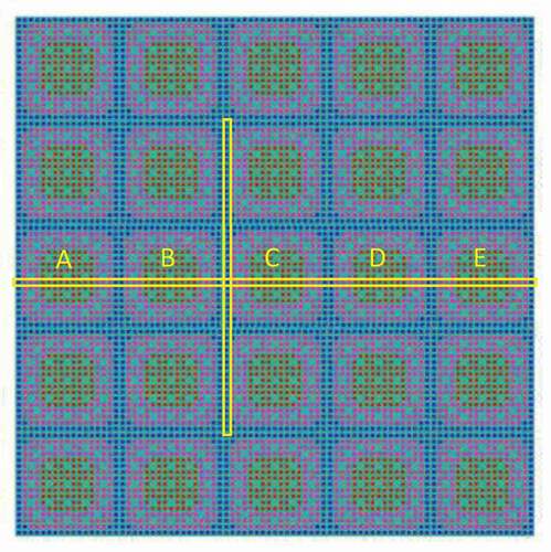
Figure 6. 5 × 5 assembly geometry with offset fuel assemblies.
The following GENESIS calculations are carried:
Reference: Uncorrected cross sections, offset geometry (as is)
Present: Corrected cross sections, nominal geometry (xs correction)
In addition, in order to estimate perturbation of pin-power due to increased assembly gap, a GENESIS calculation using the uncorrected cross section and the nominal geometry is carried out.
Calculation conditions of the GENESIS code are as follows:
Ray trace width : 0.05cm
Number of azimuthal angles : 32 (for
Number of polar angles : 4 (TY, for
Convergence criteria for flux : 10–4
Convergence criteria for keff : 10–5
shows the pin-by-pin fission rates for the increased gap (offset) configuration and the nominal configuration. The pin array within the horizontal yellow rectangle in is considered. Pin-by-pin fission rates significantly increase at the enlarged gap region (between assembly B and C) while decrease at reduced gap regions. shows a variation of pin-powers within the horizontal yellow rectangle in , calculated by EquationEquation (6)(6)
(6) , due to increased assembly gap size. corresponds to that within the vertical yellow frame in . Again, pin-power around the increased gap region increases. Note that the change of k-infinity due to variation of gap size is small in this case, i.e., less than
. Therefore, explicit comparison of k-infinity is not carried out for this case. and indicate that the present method can accurately reproduce the reference results by the correction of the cross section without explicit consideration of geometry deformation.
Figure 7. Comparison of pin-by-pin fission rate (pin array within the yellow rectangle in , from assembly A to E).
Figure 8. Perturbation of pin-powers due to increased gap size (fuel rods within the horizontal frame in ).
Figure 9. Perturbation of pin-powers due to increased gap size (fuel rods within the vertical frame in ).
3. Conclusion
A simplified treatment for increased assembly gap of offset fuel assemblies due to bowing is proposed. In the present method, nominal (non-offset) geometry is used while the cross section of the gap region is corrected to incorporate the variation of gap size. The gap size or the average chord length of a gap region is preserved to maintain the transmission probability. Verification results in the single assembly geometries and the 5 × 5 assembly geometry indicate that the present method accurately reproduces the reference results obtained by explicit consideration of the offset geometry.
Since the present method does not require any geometry change, it will be a convenient candidate for high-fidelity core simulators that explicitly consider the heterogeneous geometry. Treatment of gap size variation along axial direction due to three-dimensional bowing of fuel assembly is difficult especially for core analysis codes utilizing extruded geometry for axial direction. The present method can offer a simple modeling approach in such situation.
In this paper, the validity of the proposed method is verified by a typical situation. Verification in other conditions (e.g., use of different energy group structures, transport or diffusion method, gap size variation along axial direction) will be desirable. Effect of increased or decreased gap size on effective cross sections (e.g., capture cross section of 238U) is not taken into account in this study. Investigation on this topic will be an interesting future task.
Disclosure statement
No potential conflict of interest was reported by the authors.
Additional information
Funding
Related Research Data
References
- Fetterman R, Franceschini F Analysis of PWR assembly bow.Proc. PHYSOR 2008; 2008 Sep.14–19; Interlaken(Switzerland). [CD-ROM]
- Franzen A Evaluation of fuel assembly bow penalty peaking factors for ringhals 3 based on a cycle specific core water gap distribution. [Master Thesis], UPTEC ES 17 037; 2017; Uppsala University.
- Berger J Impact of fuel assembly bowing on the power density distribution and its monitoring in siemens/KWU-PWR. [Master Thesis], TRITA-FYS 2017:60; 2017; KTH.
- Bahadir T, Rodes J, Knott D CMS assembly bow model, 2017, Studsvik Scandpower.
- Franceschini F, Fetterman R, Little D, Modification of the ANC nodal code for analysis of PWR assembly bow. Proc. PHYSOR 2008; 2008 Sep 14–19; Interlaken(Switzerland). [CD-ROM]
- Joo HG, Cho JY, Kim KS, et al. Methods and performance of a three-dimensional whole-core transport code DeCART. Proc. PHYSOR 2004; 2004, Apr. 25–29; Chicago(IL). [CD-ROM].
- Kochunas B, Collins B, Jabaay J, et al. Overview of development and design of MPACT: Michigan parallel characteristics Transport Code. Proc. M&C2013; 2013 May.5–9; Sun Valley(ID). [CD-ROM]
- Ryu M, Junga YS, Cho HH, et al. Solution of the BEAVRS benchmark using the nTRACER direct whole core calculation code. J Nucl Sci Technol. 2015;52:961.
- Yamamoto A, Giho A, Kato Y, et al. genesis - a three-dimensional heterogeneous transport solver based on the legendre polynomial expansion of angular flux method. Nucl Sci Eng. 2017;186:1.
- Kosaka S, Saji E. transport theory calculation for a heterogeneous multi-assembly problem by characteristics method with direct neutron path linking technique. J Nucl Sci Technol. 2000;37:1015.
- Rochman D, Mala P, Ferroukhi H, et al. Bowing effects on power and burn-up distributions for simplified full PWR and BWR cores. Proc. M&C 2017; 2017 Apr 16–20; Jeju, Korea. [USB-DRIVE].
- Yamamoto A, Kitamura Y, Yamane Y. Approximate treatment of thermal expansion effect in lattice transport calculations. J Nucl Sci Technol. 2004;41:1003.
- Reed M, Smith K, Forget B. “Virtual density” and traditional boundary perturbation theories: analytic equivalence and numeric comparison, ann. Nucl Energy. 2018;112:531.
- Cho NZ, Benchmark problems in reactor and particle transport physics. 2000; http://nurapt.kaist.ac.kr/benchmark/.