
 ?Mathematical formulae have been encoded as MathML and are displayed in this HTML version using MathJax in order to improve their display. Uncheck the box to turn MathJax off. This feature requires Javascript. Click on a formula to zoom.
ABSTRACT
After the core meltdown in the Fukushima Daiichi (1F) nuclear power plant, various compounds in metal boride systems could potentially form as a result of the reactions between B4C (control material) and Fe, Zr alloys (control-blade sheaths, zircaloy claddings, channel box, etc.). Some previous studies have focused on the properties of intermetallic compounds of the Zr-B and Fe-B systems, such as ZrB2, FeB, and Fe2B. However, during the solidification of fuel debris, composites of these intermetallics rather than large chunks of single-phase intermetallics will form. This situation makes the understanding of the composition dependence of the mechanical and thermal properties of these metal borides a major task before debris retrieval takes place. In this study, we first investigated the temperature-dependent thermal conductivity of Fe-B and Zr-B eutectics from room temperature up to 900°C. We were then able to evaluate the composition-dependent indentation hardness of these metal borides at room temperature. Based on our experimental data, we concluded that the hardness and thermal conductivity of the Fe-B, Zr-B composites can be well estimated using the properties of the composites’ corresponding components, with Rule of Mixtures and Effective Medium Theory (EMT) calculations, respectively.
1. Introduction
During the Loss of Coolant Accident (LOCA) in the Fukushima Daiichi (1F) nuclear power plant, large amounts of heat were generated and the control rods containing B4C and stainless steel reacted with the fuel rods and channel box (zirconium alloys) to form molten mixture that solidified to form alloys, intermetallic compounds, and borides [Citation1]. A major keystone in the decommissioning process is the removal of fuel debris with methods such as bore drilling, laser cutting [Citation2–Citation4]. However, before such activities can take place, it is necessary to know both the hardness of the fuel debris and thermal conductivity to understand how easily can the heat generated from breaking the debris dissipate away. These information are essential as borides are expected to have much higher hardness than those of oxides (e.g. (U,Zr)O2 [Citation5]), alloys (e.g. Fe-Cr-Ni alloys [Citation5]), and intermetallic compounds (e.g. Fe2Zr [Citation6]) formed during core meltdown.
Our group has previously reported the thermophysical and mechanical properties of Zr-B and Fe-B intermetallic compounds such as FeB [Citation7], Fe2B [Citation8], ZrB2 [Citation9], etc. However, during the cooling/solidification of the fuel debris, not only singe phase intermetallics but composites of these intermetallic compounds will form. How well can we theoretically estimate the properties of these composites based on those of their components still remains unclear. Thus, in this study, our focus is on evaluating the hardness and thermal properties of intermetallic compound composites. This will allow us to further understand the composition dependence of metal borides that formed after core meltdown took place.
2. Experimental procedures
ZrxB1-x (x = 0.68, 0.86) and FexB1-x (x = 0.37, 0.84) samples were fabricated by arc melting zirconium (Rare Metallic, 3N), iron (Kojundo Chemicals, 4N), and boron (Furuchi Chemicals, 3N) under an argon atmosphere. Most of the samples are at the eutectic compositions chosen based on the binary phase diagrams of Zr-B and Fe-B systems shown in . Only one random non-eutectic composition, Zr0.68B0.32, was chosen to help us understand the differences in microstructures between the eutectic and non-eutectic samples. In this study, we are more focused on the eutectic compositions because, with increasing temperature inside the core, liquids with eutectic compositions will be the first to form, drop, and solidify. Also, we expect the eutectic’s fine microstructures to allow for more precise hardness measurements using a micro-indenter. Differences in the size of the microstructures can be assessed by comparing the SEM images of Zr0.68B0.32 with that of Zr0.86B0.14. The prepared ingots after arc melting were then cut and polished for further measurements.
Figure 1. Phase diagrams of Fe-B and Zr-B systems, sample compositions marked in lines [Citation10,Citation11].
![Figure 1. Phase diagrams of Fe-B and Zr-B systems, sample compositions marked in lines [Citation10,Citation11].](/cms/asset/a02e6754-6f97-4fac-9291-67d66c043df0/tnst_a_1736201_f0001_oc.jpg)
Prepared bulk samples’ phases were identified using X-ray Diffraction (Ultima-IV, Rigaku), with scanning angle 2 from 20
to 80
, Cu-K
radiation, and a scintillation detector. Samples’ surface morphology and element distribution were investigated using Scanning Electron Microscope (JSM-6500F, JEOL) and Energy Dispersive X-ray Spectroscopy (EDX-64175JMU, JEOL). Hardness measurements were conducted using a micro Vickers hardness tester (HMV-1, Shimadzu), with a 9.8 N load, 10 s holding time, a pyramidal diamond indenter, and 10 indentations were made per sample. The indentations left on the samples were then observed with a laser microscope (OLS30-SU, Olympus). Vickers hardness,
, can be expressed as:
where is the load (N),
is the indentation size (mm2),
is the indentation’s diagonal length (mm), and
is the angle between the plane faces of the indenter tip (
).
Thermal diffusivity was measured using the NETZSCH 457 Microflash under a constant argon flow (5N). For each of the samples, three measurements were taken at room temperature, and then every 100 K from 373 K to 1173 K. Uncertainties in the measured results were determined using standard error. Thermal conductivity was then derived using thermal diffusivity, density, and specific heat with the following equation:
Here, is the thermal diffusivity (m2/s),
is the specific heat (J/(kg K)) [Citation8,Citation12], and
is the density (kg/m3) [Citation9,Citation13–Citation19]. Fe-B and Zr-B binary systems have small solid solution regions which led us to assume that at our selected compositions, both the excess specific heat and excess volume are zero:
and
are the individual components of the composite, e.g. Fe2B and Fe for Fe0.84B0.16.
After laser flash measurements, sample compositions were determined with Inductively Coupled Plasma Mass Spectrometry (ICP-MS). The determined compositions are shown in and changes in the sample compositions during measurements are negligible.
Table 1. Sample compositions of the as-prepared Zr-B and Fe-B samples and ICP-MS results.
3. Results and discussion
3.1. Phase and microstructure
3.1.1. X-ray diffraction
The X-ray diffraction patterns of Zr-B and Fe-B alloys and reference data [Citation20–Citation25] are shown in . For both Zr0.86B0.14 and Zr0.68B0.32, -Zr and hexagonal (P6/mmm) ZrB2 peaks were present in the XRD patterns; for the Fe0.84B0.16 sample, both cubic (Im-3m) Fe and tetragonal (I4/mcm) Fe2B peaks were observed in the XRD patterns. These phases are just the ones we expected to observe, judging from the phase diagrams of the two systems. The diffraction peaks of the Fe0.37B0.63 sample match well with those of FeB, but it is difficult to locate the boron peaks because
-boron’s complicated structure, its few number of electrons, and the possible low degree of crystallinity all could result in very low-intensity boron peaks that are hard to observe with XRD.
Figure 2. XRD patterns of (a) Zr-B and (b) Fe-B samples.
3.1.2. SEM/EDS
The degree of element homogeneity of the sample, as well as the grain size, was investigated using scanning electron microscopy/energy-dispersive X-ray spectroscopy (SEM/EDS) before Vickers hardness test took place. Based on the element mappings of the Fe-B and Zr-B samples ( and ), we were able to confirm that homogeneous samples were fabricated from arc melting, without the formation of large precipitates.
Figure 3. SEM images and element mappings of (a) Fe0.84B0.16 (b) Fe0.37B0.63 (c) Zr0.86B0.14.
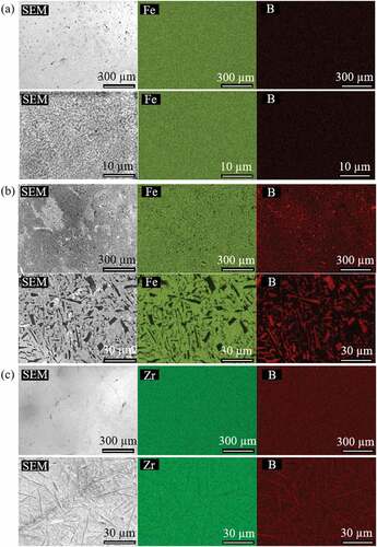
Figure 4. SEM image and element mappings of Zr0.68B0.32.
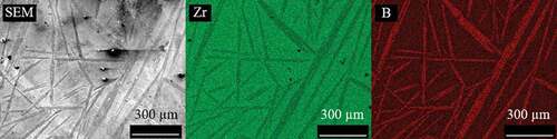
Two major types of precipitates, needle-shaped and plate-shaped, could be observed in the SEM images. The key difference in their morphology is that needle-shaped precipitates have larger aspect ratios than plate-shaped ones do. For the two Fe-B eutectic samples, plate-shaped boride precipitates with lengths from a few microns to tens of microns were observed in their SEM images, with Fe0.37B0.63 having a larger precipitate size. On the other hand, the needle-shaped boride precipitates in both of the Zr-B samples shown in ) and have much larger aspect ratios with lengths on the order of a few tens to a few hundred microns. Differences between the microstructure of the eutectic and non-eutectic samples are obvious: under the same magnification, the size of the precipitates in the Zr-B eutectic sample is much smaller.
3.2. Vickers indentation hardness
The indentations on the surfaces of the samples from Vickers hardness tests are shown in and . As seen from ), the indentation on Zr0.68B0.32 has a rather distorted shape with uneven edges, unlike the distinct rhombus-shaped dent shown in ) for Zr0.86B0.14, due to the large precipitated ZrB2 in the non-eutectic sample. The distorted indentation shape and the cracks generated within the ZrB2 precipitates can be well explained by the high hardness and brittleness of ZrB2 [Citation9]. Similar to that shown in ) for the eutectic Zr-B sample, distinct rhombus-shaped indentations can be seen in both of the Fe-B eutectic samples (). Given the distorted indentation shape and that the indentation was unable to cover the area of multiple grains in the Zr0.68B0.32 sample, its indentation hardness result will not be reported here.
Figure 5. Vickers hardness measurement indentations on (a)Zr0.68B0.32 (b)Zr0.86B0.14.
Figure 6. Vickers hardness measurement indentations on (a)Fe0.84B0.16 (b)Fe0.37B0.63.
The calculated indentation hardness of the three samples (see ) along with referenced hardness data of the intermetallic compounds [Citation7–Citation9,Citation26,Citation27] are shown in in terms of precipitate volume fractions. To obtain the volume fractions, we had to first use the lever rule at the respective sample compositions to determine the mole and weight fractions of the precipitate and the matrix. We assumed that the densities of the pure compounds and metals [Citation9,Citation13–Citation19] do not change when they combine to form composites as no solid solution regions were observable in the phase diagrams shown in . This allowed us to convert between boron compositions and boride precipitate volume fractions. As expected, for all three samples, the introduction of much harder second phases into the softer matrices increased the indentation hardness. However, the increase in composites’ hardness values does not seem to increase linearly with precipitate volume fraction, and is especially small for the case of Zr0.86B0.14. To understand such behavior, we calculated the upper bound (Voigt model [Citation28]) and lower bound (Reuss model [Citation29]) of hardness for both systems, plotted as lines in , using the rule of mixture [Citation30]. The two models assume the precipitates and the matrix are ideally aligned in such a way that allows them to either undergo equal deformation (iso-strain, Voigt model) or experience equal stress (iso-stress, Reuss model). The realistic situation, shown in , is somewhere between the two idealistic cases described by the two models. Based on our rule of mixture calculations, we confirmed that the low hardness values we observed in Zr0.86B0.14 and Fe0.84B0.16 lie well within the calculated theoretical boundaries. This only slight increase in hardness can be further explained by the fact that at low precipitate volume fraction, the deformation from indentation is inhomogeneously received, with the softer matrix being mainly deformed [Citation31,Citation32], which results in the effective hardness of the sample to heavily depend on that of the soft Zr, Fe matrix.
Figure 7. The iso-strain Voigt model, iso-stress Reuss model, as well as what we expect under realistic situations.
Figure 8. Relationship between precipitate volume fraction and indentation hardness of (a) Zr-B (b) Fe-B alloys.
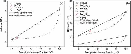
Table 2. Indentation hardness of Zr-B and Fe-B alloys.
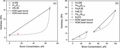
For the purpose of debris removal, it is also practical to understand how boron concentration affects the hardness of these metal boron systems. For this reason, in , the boron concentrations of the samples are shown on the x-axis, and we can observe increases in indentation hardness with increasing boron concentration. The indentation hardness data of these eutectic samples are shown in .
Figure 9. Relationship between boron composition and indentation hardness of (a) Zr-B (b) Fe-B alloys.
3.3. Thermal conductivity
The calculated thermal conductivity of Zr0.86B0.14, Fe0.37B0.63, Fe0.84B0.16, and other referenced Zr and Fe borides data [Citation7–Citation9,Citation33–Citation35] are shown in . Theoretical estimation of the composites’ thermal conductivity using the Effective Medium Theory (EMT) was also performed and shown as dashed lines along with experimental data. Bruggeman’s formula [Citation36] was used here for our EMT calculations,
where is the volume fraction of the precipitate phase,
,
, and
are the thermal conductivity of the matrix, the precipitate, and the effective thermal conductivity, respectively. The Bruggeman’s model was chosen as it is one of the more general and accurate EMT models up until high volume fractions. However, some deviations in thermal conductivity from our experimental data are expected as the Bruggeman’s model assumes the precipitates are isolated spheres. Although EMT models such as the Rayleigh model and the Lewis-Nielsen model [Citation37] allow for thermal conductivity calculations on composites with rod-shaped precipitates, the aspect ratios of the precipitates are not well defined and vary within each given sample in this study, which makes calculation using these models rather difficult.
For Zr0.86B0.14, the calculated thermal conductivity from thermal diffusivity is slightly temperature dependent, increasing from 18 W/mK at 100C to 32 W/mK at 900
C. Estimation of the composite’s thermal conductivity with Equation.5 for the Zr-B eutectic seems very similar to that of pure zirconium [Citation33]. However, this small mismatch could have resulted from the assumption made by the Bruggeman’s model that the precipitates are non-interacting spheres. Whereas for the microstructure of Zr0.86B0.14 shown in ), the precipitated ZrB2 phases are connected, needle-shaped rather than spherical.
At room temperature, the thermal conductivity of Fe0.37B0.63 and Fe0.84B0.16 are 11 W/mK and 41 W/mK, respectively. For the Fe-B eutectics, the thermal conductivity of Fe0.37B0.63 is similar to those of Fe2B [Citation8] and FeB [Citation7], hinting that the thermal conductivity of Fe-B alloys probably stays rather constant once a certain boron concentration threshold is reached. For Fe0.84B0.16, based on its SEM images, boron precipitates are relatively isolated (no mutual interaction) and can be roughly assumed to take on a spherical shape. EMT calculations using Bruggeman’s formula in show good agreement with our experimental data. A small overestimation in thermal conductivity with Bruggeman’s formula is observed, and this overestimation can be attributed to the neglect of interfacial thermal resistance in the EMT model.
Figure 10. Relationship between temperature and thermal conductivity of (a) Zr-B (b) Fe-B alloys.
As for the composition dependence at room temperature, the temperature at which decommissioning and debris removal are taking place, boron concentration affects heat conduction in Fe-B and Zr-B alloys quite differently, as shown in and . For Zr-B alloys, there seems to be little change in their thermal conductivity with a small addition of boron (until 14 at. % as shown in this study) as the amount of ZrB2 precipitate volume fraction is only around 10%. However, based on Bruggeman’s equation and the high thermal conductivity of ZrB2 [Citation9] precipitates, as the boron concentration increases and the precipitated ZrB2 volume fraction increases, we should expect the thermal conductivity of Zr-B alloys to increase rapidly between 14 at. % and 67 at. % boron. On the other hand, for Fe-B alloys, the thermal conductivity first decreases with increasing boron content and then stays rather constant as the boron concentration exceeds 30 at. %.
Figure 11. Composition dependence of thermal conductivity for Zr-B and Fe-B alloys at room temperature.
Table 3. Thermal conductivity of Fe-B and Zr-B at room temperature.
4. Conclusion
In this study, we investigated the hardness and thermal conductivity at several eutectic compositions, Zr0.86B0.14, Fe0.84B0.16, Fe0.37B0.63, of the Fe-B and Zr-B systems. Samples with non-eutectic compositions were shown to have coarse microstructures. Vickers hardness measurements were performed at the three eutectic compositions and the general trend observed was an increase in indentation hardness with increasing boron concentration. At room temperature, the indentation hardness of Zr0.86B0.14, Fe0.37B0.63, and Fe0.84B0.16 are 2.02 GPa, 18.3 GPa, and 4.60 GPa, respectively. As for their thermal properties, theoretical estimations using Bruggeman’s model showed good agreement with experimentally determined temperature-dependent thermal conductivity data. At room temperature, an increase in boron composition affects the thermal conductivity differently in the two systems, increasing the thermal conductivity for the Zr-B system while decreasing that for Fe-B. We reasoned that this increase in Zr-B thermal conductivity results from the increase in the volume fraction of the precipitated highly heat-conducting ZrB2 in Zr-B alloys with the addition of boron.
Disclosure Statement
No potential conflict of interest was reported by the authors.
References
- Washiya T. Fundamental research program for removal of fuel debris. Tokyo (Japan): Japan Atomic Energy Agency; 2012.
- Nuclear Damage Compensation and Decommissioning Facilitation Corporation (Japan). Technical Strategic Plan 2018 for the Decommissioning of the Fukushima Daiichi Nuclear Power Station of Tokyo Electric Power Company Holdings, Inc; 2018.
- Porter HL, Austin EW. Disassembly and defueling of the three mile island unit 2 reactor vessel lower core support assembly. Nucl Technol. 1989;87(3):595–608.
- Journeau C, Roulet D, Porcheron E, et al. Fukushima Daiichi fuel debris simulant materials for the development of cutting and collection technologies. J Nucl Sci Technol. 2018;55(9):985–995.
- Washiya T, Ogino H, Takano M, et al. Approach to estimating fuel debris properties generated in Fukushima Daiichi NPS. In: HOTLAB 2016 - Annual meeting on hot laboratories and remote handling; 2016 Oct 2; Karlsruhe, Germany.
- Okada D, Ishii H, Ohishi Y, et al. Thermal and mechanical properties of Fe2Zr. Trans At Energy Soc Jpn. 2019;18(1):37–42. [in Japanese].
- Ohishi Y, Sugizaki M, Sun Y, et al. Thermophysical and mechanical properties of CrB and FeB. J Nucl Sci Technol. 2019;56:859–865.
- Nakamori F, Ohishi Y, Kumagai M, et al. Mechanical and thermal properties of Fe2B. Trans At Energy Soc Jpn. 2016;15:223–228. [in Japanese].
- Nakamori F, Ohishi Y, Muta H, et al. Mechanical and thermal properties of bulk ZrB2. J Nucl Mater. 2015;467:612–617.
- Massalski BT, Okamoto H, Subramanian RP, et al. Binary alloy phase diagrams. 2nd ed. Ohio: ASM International; 1990. p. 560–561.
- Hallemans B, Wollants P, Roos J. Thermodynamic reassessment and calculation of the Fe-B phase diagram. Z Metallkd. 1994;85:676–682.
- Bale WC, Bélisle E, Chartrand P, et al. FactSage thermochemical software and databases. CALPHAD. 2016;54:35–53.
- Haynes MW. CRC handbook of chemistry and physics. 92nd ed. Florida: CRC Press; 2011–2012. Table 4–68.
- Slack AG, Hejna IC, Garbauskas FM, et al. The crystal structure and density of β-rhombohedral boron. J Solid State Chem. 1988;76:52–63.
- Skinner BG, Johnston LH. Thermal expansion of zirconium between 298K and 1600K. J Chem Phys. 1953;21:1383–1384.
- Lundström T, Lönnberg B, Bauer J. Thermal expansion of β-rhombohedral boron. J Alloy Compd. 1998;267:54–58.
- Jankowiak A, Justin FJ. Ultra high temperature ceramics: densification, properties and thermal stability. J Aerosp Lab. 2011;3:1–11.
- Gale FW, Totemeier CT. Smithells metals reference book (Eighth edition). Oxford: Butterworth-Heinemann; 2004. 14, General physical properties; 14-1–14-45.
- Kunitskii AY, Marek VÉ. Some physical properties of iron borides. Poroshkovaya Metallurgiya. 1971;99:56–59. [in Russian].
- International Centre of Diffraction Data, Joint Committee on Powder Diffraction Standards (JSPDS). Card No. 00-006-0696.
- International Centre of Diffraction Data, Joint Committee on Powder Diffraction Standards (JSPDS). Card No. 00-036-1332.
- International Centre of Diffraction Data, Joint Committee on Powder Diffraction Standards (JSPDS). Card No. 01-089-3045.
- International Centre of Diffraction Data, Joint Committee on Powder Diffraction Standards (JSPDS). Card No. 00-034-0423.
- International Centre of Diffraction Data, Joint Committee on Powder Diffraction Standards (JSPDS). Card No. 00-032-0463.
- International Centre of Diffraction Data, Joint Committee on Powder Diffraction Standards (JSPDS). Card No. 01-085-0409.
- Samsonov VG. Handbook of the physicochemical properties of the elements. New York: Springer US; 1968.
- Bolmgren H, Lundström T, Okada S. Structure refinement of the boron suboxide B6O by the Rietveld method. AIP Conf Proc. 1991;231(1):197–200.
- Voigt W. Ueber die Beziehung zwischen den beiden Elasticitätsconstanten isotroper Körper. Ann Phys. 1889;274:573–587. [in German].
- Reuss A. Berechnung der Fließgrenze von Mischkristallen auf Grund der Plastizitätsbedingung für Einkristalle. J Appl Math Mech. 1929;9:49–58. [in German].
- Kim SH. On the rule of mixtures for the hardness of particle reinforced composites. Mater Sci Eng A. 2000;289(1–2):30–33.
- Greer LA. Partially or fully devitrified alloys for mechanical properties. Mater Sci Eng A. 2001;340–306:68–72.
- Zhong CZ, Jiang YX, Greer LA. Nanocrystallization in Al-based amorphous alloys. Philos Mag B. 1997;76(4):505–510.
- Fink KJ, Leibowitz L. Thermal conductivity of zirconium. J Nucl Mater. 1995;226:44–50.
- Hust GJ, Lankford BA. Thermal conductivity of aluminum, copper, iron, and tungsten for temperatures from 1K to melting point. USA: NationalBureau of Standards; 1984. NBSIR 84-3007.
- Kim H, Kimura K. Vanadium concentration dependence of thermoelectric properties of β-rhombohedral boron prepared by spark plasma sintering. Mater Trans. 2011;52(1):41–48.
- Bruggeman DAG. Berechnung verschiedener physikalischer Konstanten von heterogenen Substanzen. I. Dielektrizitätskonstanten und Leitfähigkeiten der Mischkörper aus isotropen Substanzen. Ann Phys. 1935;416:636–664. [in German].
- Pietrak K, Wiśniewski T. A review of models for effective thermal conductivity of composite materials. J Power Technol. 2015;95(1):14–24.