ABSTRACT
The tritium exhaust behavior from the Large Helical Device (LHD) was observed in the first deuterium plasma experimental campaign. Tritium in the exhaust gas was monitored at the conducted by use of the ionization chamber and water bubbler system with the discrimination of chemical forms. The observation results indicated that (i) tritium on the surface of the first wall and divertor tiles as plasma facing components was released by the hydrogen isotope exchange reaction of the glow discharge cleaning operation and the diffusion-limited process was suggested in the tritium release behavior from the bulk, (ii) the amount of tritium release from the LHD vacuum vessel was about one-third of the produced tritium and the mostly produced tritium was still retained at the end of plasma experimental campaign, (iii) the ratio of exhausted tritium from the LHD vacuum vessel was larger than that in the case of JT-60U based on the carbon materials as the plasma-facing components. It indicated that the tritium inventory would be reduced and controlled by the kind of plasma-facing materials.
1. Introduction
The management and control of tritium in the fusion facilities are one of the key issues for public acceptance and the realization of a nuclear fusion reactor. Therefore, the behavior of tritium should be understood to control the tritium in a fusion test device. The tritium exhaust behavior and tritium inventory on the deuterium plasma experiment have been reported by JT-60U, JET, and DIII-D [Citation1–11]. In the deuterium plasma experiment by a large fusion test device, a small amount of tritium, which has the maximum energy of 1.01 MeV, is produced by d(d, p)t reaction in core plasma. A part of produced tritium is exhausted from the vacuum vessel via the vacuum pumping system and the rest of the tritium would be retained in the vacuum vessel. These sources of tritium can be utilized as a tracer in a fusion test device. One of the applications is to quantitatively determine the tritium balance in the vacuum vessel and release pathways of tritium from a fusion test device. Other applications are to observe tritium exhaust behavior and determine the chemical forms of tritium in the exhaust gas. The observation of the tritium behavior in the exhaust gas also indicates the tritium release properties from the plasma-facing components. As a result, the tritium inventory and behavior in the fusion test device would be revealed.
At National Institute for Fusion Science (NIFS), the first deuterium plasma experiment using Large Helical Device (LHD), which is the largest helical type fusion test device equipped with the superconducting magnet system, has been started from 7 March 2017 [Citation12,Citation13]. After starting the deuterium plasma experiment, exhausted tritium was observed during the plasma experiment. Exhausted tritium from the vacuum vessel has to be recovered by the tritium removal system such as an exhaust detritiation system (EDS) from the viewpoints of public acceptance. Thus, EDS has been installed at the downstream of vacuum pumping gas lines [Citation14]. All exhaust gas lines from the LHD and Neutral Beam Injection (NBI) systems and so on had to be connected to the EDS for tritium recovery. Therefore, the inlet of EDS was suitable for the observation of tritium behavior in the exhaust gas.
In this study, we observe the tritium in the LHD exhaust gas by the tritium monitoring system and discuss the tritium release behavior and mass balance of tritium in the first deuterium plasma experiment.
2. Plasma exhaust system and LHD operations
2.1. The vacuum pump system and wall conditioning system in LHD
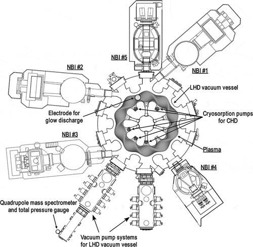
The layout of the LHD and the auxiliary system is shown in . The plasma-facing components in LHD mainly consist of stainless steel for the first wall and carbon for divertor tiles. These materials combination of plasma-facing components are different from other large fusion test devices such as JT-60U using the carbon-based first wall [Citation2] and JET using the carbon or beryllium wall in the deuterium plasma phase prior to the preliminary tritium experiment [Citation8].
The LHD is equipped with various components of vacuum pumping systems for the LHD vacuum pump system, NBI systems for plasma heating, in-vessel cryosorption pumps for closed helical divertor (CHD), glow discharge cleaning system and wall baking system at 368 K, number of plasma diagnostic devices and so on. These components are installed with many independent vacuum pumping systems that are operated continuously. However, the produced tritium is mainly exhausted via the vacuum pump systems for the LHD vacuum vessel and NBI, and the cryosorption pumps for CHD. The vacuum pump systems for LHD vacuum vessel consists of two systems: one system has 10 cryosorption pumps and 6 turbomolecular pumps, another system has 8 cryosorption pumps and 2 turbomolecular pumps. Two vacuum pump systems are installed side by side in a part of the vacuum vessel as shown in . The total practical pumping speed of hydrogen gas is estimated to be a few hundred m3/s. The vacuum pump system for an NBI mainly consists of a large cryosorption pump developed by NIFS and 2 turbomolecular pumps. The NBIs are installed almost equally in the rest of the vacuum vessel as shown in . The total practical vacuum pumping speed by 5 NBI vacuum pump systems of hydrogen gas is estimated to be a few hundred m3/s. It corresponds to the performance of the vacuum pump system for the LHD vacuum vessel. The five CHD pumping system by means of the cryosorption system was installed in the LHD divertor region to control the neutral gas pressure. The practical vacuum pumping speed of hydrogen gas per one system is 9 m3/s [Citation15]. These cryosorption pumps were regenerated after plasma experiment in a day or on a weekend. The detailed operation procedures are described in section 2.3.
As for the wall conditioning in the vacuum vessel, the glow discharge cleaning, boronization, and wall baking were conducted. The glow discharge cleaning operation was carried out after the plasma experiment in a day or weekend as required by the researcher. One electrode for glow discharge cleaning was installed in the LHD vacuum vessel in the first deuterium plasma experiment campaign. Helium, hydrogen (H2), and deuterium (D2) were utilized as the discharge gas. The boronization of the vacuum vessel during the deuterium plasma experiment was limited to one operation. The discharge cleaning condition is summarized in . The wall baking operation at 368 K was also carried out as required. The rate of temperature increase was 5 K/h. The baking temperature was kept for a few ten hours. These wall conditioning operations were carried out after the regeneration of the CHD cryosorption pump. The gate values for the cryosorption pumps were closed during the wall conditioning operation and only turbomolecular pumps were used for the exhaust of operation gas and outgas.
Table 1. Operating conditions for glow discharge, Boronization, and baking
Table 2. Comparison of tritium exhaust rate in the initial deuterium plasma phase among the large fusion test devices
2.2. Exhaust detritiation system and tritium monitoring system
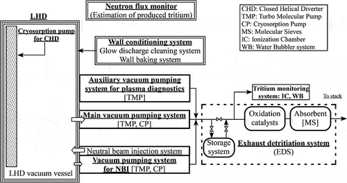
A schematic diagram of the LHD vacuum pumping system and the exhaust detritiation system (EDS) is shown in . The exhaust gas lines from all vacuum pumping systems are integrated and connected to the EDS for tritium removal. The length and volume of exhaust gas lines from LHD to EDS are estimated to be approximately 100 m and 1 m3, respectively. The EDS as a tritium recovery system mainly consists of the catalytic reactors for the hydrogen conversion to water vapor, molecular sieves columns for the recovery of water vapor and temporally gas storage system for the regeneration gas from cryosorption pump, etc. The detail process flow diagram, the operation, and the specifications of the EDS are described in Ref. [Citation14].
The tritium monitoring system has been developed and installed at the inlet of the EDS as shown in . The tritium monitoring system consists of the water bubbler system for the measurement of total tritium amount and the discrimination of tritium chemical forms, and the ionization chamber for the observation of tritium exhaust behavior. These detection limits were about 10−7 MBq/m3 and 4 × 10⁻² MBq/m3, respectively. The detail tritium monitoring system is described in Ref. [Citation16].
2.3. Operation of LHD in the first deuterium plasma experiment
The first deuterium plasma experiment in LHD has started on March 7th, 2017. The plasma operation using deuterium gas (D2), ‘D phase’, was carried out until June 30th, 2017. Then the plasma operation gas was changed to hydrogen gas (H2), ‘H phase’, and carried out until August 3rd, 2017. The total amount of produced tritium was evaluated by three neutron flux monitors [Citation17,Citation18]. The uncertainty of the neutron flux monitor was estimated to be about 10% on the calibration factor [Citation17]. The total amount of produced tritium in the first deuterium plasma campaign was estimated to be about 6.4 GBq. The detail deuterium plasma operation of LHD with NBI heating is described in Ref. [Citation12].
The LHD plasma experimental operation in a week was from Tuesday to Friday. The operation gas was exhausted by the vacuum pump systems. After the plasma experiment in a day, the cryosorption pumps for CHD were usually regenerated and then the released hydrogen isotope gas contained with tritium was directory exhausted via the turbo molecular pump in the vacuum pump system for LHD vacuum vessel. After the plasma experiment on Friday, the large volume cryosorption pumps for the NBI system were regenerated at night. Since a large volume of hydrogen isotope gas was released from the NBI cryosorption pumps for a few hours, the released hydrogen isotope gas was temporally stored in a buffer tank in the EDS. After the regeneration of NBI cryosorption pumps, the stored hydrogen isotope gas was introduced into the oxidation catalyst reactor by a controlled flow rate to be 0.4% of hydrogen concentration at the inlet of the reactor. At the same time, the cryosorption pumps in the main vacuum pumping system were regenerated one after another at certain intervals.
3. Results and discussion
3.1. Exhaust behavior of tritium
3.1.1. LHD deuterium plasma operation
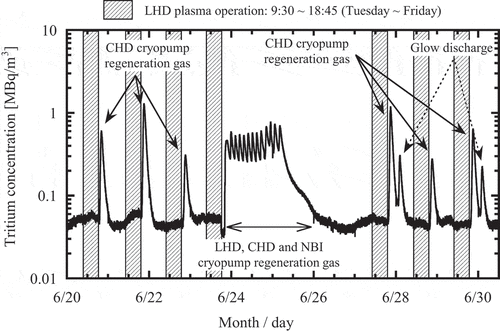
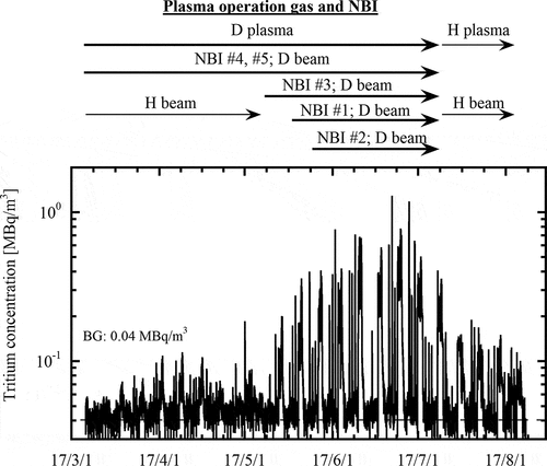
The behavior of tritium in the exhaust gas from the LHD vacuum vessel was measured by the ionization chamber. The volume of the ionization chamber and the sampling gas flow rate were 10−2 m3 and 1.2 m3/h, respectively. shows the variation of tritium concentration in the exhaust gas during the LHD deuterium plasma experimental campaign. In the first two months as the initial D phase, the deuterium plasma experiment was conducted using deuterium plasma heated by two deuterium beams (NBI: #4, #5) and three hydrogen beams (NBI: #1, #2, #3). Thus, produced tritium amount by D-D reactions was small, and observed tritium concentration in the exhaust gas was low. The maximum tritium concentration was 0.183 MBq/m3. Then the number of deuterium beams was increased week by week and the deuterium plasma operation as full D phase was started on May 23rd, 2017. The amount of produced tritium in the core plasma increased as the number of deuterium beams. The maximum tritium concentration was reached at 1.28 MBq/m3 on June 21st, 2017. Then, the plasma operation gas and neutral beams were changed to hydrogen from the beginning of July as the H phase. Even though tritium was not produced in the core plasma in the hydrogen plasma operation phase, a tritium concentration of more than 0.1 MBq/m3 was observed in the exhaust gas. Since produced tritium was remained in and on the plasma-facing components, it would be released from the components during these hydrogen plasma operations.
Figure 3. Variation of tritium concentration measured by an ionization chamber in the exhaust gas during the plasma experiments
shows an example of the variation of tritium concentration for 10 days. Tritium in the exhaust gas was not observed in the term of the deuterium plasma operation, because the main vacuum pumps were consisted of cryosorption type pumping system and produced tritium was not exhausted directly. After the plasma operation in a day, the gate valves of the cryosorption pumps in the main vacuum pump system were closed and then the cryosorption pump for CHD in the vacuum vessel was regenerated at night. Tritium was desorbed from the CHD cryosorption pump and exhausted by turbomolecular pumps. Thus, the peaks of tritium concentration were observed on the night of each day. Some of the deuterium glow discharge cleaning operations were conducted after the regeneration of CHD cryosorption pumps and the peak of tritium concentration was also observed separately. The cryosorption pump system in the NBIs was regenerated on Friday night. At the same time, the regeneration of two cryosorption pumps in the LHD main vacuum pump system was also started. These regeneration gasses were temporally stored in the gas storage system as shown in . After the gas storage operation, the stored gas was introduced gradually into the EDS process line in a weekend. The base tritium concentration in a weekend was caused by the stored gas. On the same weekend, all cryosorption pumps in the LHD main vacuum pump system were regenerated. Therefore, some of the peaks of tritium concentration were observed on the base tritium concentration. The base tritium concentration and each observed peak signal indicate the pathway of tritium release from the vacuum vessel. Therefore, the tritium exhaust pathway can discriminate by the analysis of these signals. The tritium exhaust pathway from the LHD vacuum vessel using the data is discussed in section 3.2.
3.1.2. Wall conditioning operation: a glow discharge cleaning
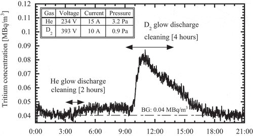
The wall conditioning operations were conducted after deuterium plasma operation in a day or a weekend. The typical tritium exhaust behavior by glow discharge cleaning operations in the initial D phase is shown in . The glow discharge operations of helium and deuterium gas were carried out from 3:00 to 5:00 and from 9:00 to 14:00 on May 3rd, 2017, respectively. Each glow discharge operation condition is summarized in . In the case of helium glow discharge, tritium release from the vacuum vessel was almost undetectable by the ionization chamber. However, it was determined less than 0.04–0.05 MBq/m3 measured by a proportional counter in the helium glow discharge with Boronization operation. On the other hand, tritium release could be detected by the deuterium glow discharge operation in spite of after the helium glow discharge. The tritium release amount was estimated to be about 2.8 MBq. The average tritium release rate was calculated to be 0.56 MBq/h. Although the mass of gas species was the same in both glow discharge operations, tritium release behavior was different. It would be caused by the different tritium release mechanism. It is well-known that the hydrogen isotope exchange reaction on the surface by the hydrogen isotope glow discharge operation is more effective to remove tritium rather than physical sputtering by the He glow discharge operation.
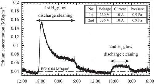
shows the behavior of tritium release by H2 glow discharge cleaning operation in the H phase. The glow discharge cleaning operation condition is summarized in . The glow discharge cleaning operations were conducted two times at an interval of 12 hours on July 10th and 11th 2017. The plasma experiment was not carried out between two glow discharge operations. The tritium release amount by first and second glow discharge cleaning operations was estimated to be about 13.7 MBq and 1.9 MBq, respectively. The average tritium release rates were 1.1 MBq/h and 0.31 MBq/h, respectively. The peak of tritium concentration was observed at the initiation of glow discharge in the first glow discharge operation. Then the tritium concentration was gradually decreased and approaching the constant value. In the second H2 glow discharge cleaning operation, the peak of tritium concentration was not observed at the initiation of glow discharge. It would indicate that the tritium on the surface was almost removed by the first glow discharge cleaning operation and then released tritium by the second glow discharge operation would be migrated from the bulk of plasma-facing components. Therefore, the glow discharge cleaning operation using hydrogen isotope gases is an effective tritium removal method, however, the long operation time is not useful because the tritium release rate decreases with the operation time.
The tritium on the surface is easily released by an isotope exchange reaction. On the other hand, since the maximum energy of triton produced by d(d, t)p reaction is 1.01 MeV, the tritium would be implanted to a depth of few µm in the first wall and divertor tiles [Citation19,Citation20]. Most of the tritium implanted in the bulk must be diffused to the surface for tritium release. The carbon is mainly deposited on the surface of the first wall near the divertor tiles [Citation21,Citation22]. On the other hand, the surface of the first wall at the center of the saddle portion is eroded by plasma. Also, the outer torus side is deposition-dominant, while the inner torus side is primarily erosion-dominant. Therefore, the tritium release behavior from the LHD vacuum vessel would be a diffusion-limited process in bulk metal as well as in the deposition layer on the plasma facing materials.
3.1.3. Wall conditioning operation: wall baking
The wall baking operation was carried out following to deuterium glow discharge cleaning operation as shown in . shows the variation of tritium concentration in the exhaust gas, vacuum vessel temperature, gas species measured by a mass spectrometer, and total pressure in the mass spectrometer chamber during the baking operation. The gas species and total pressure were measured by a quadrupole mass spectrometer (MKS Instruments, e-Vision2 RGA) and an ionization vacuum gauge (ULVAC, GI-M2). The flat top of the wall temperature at 368 K was kept for 66 hours. The tritium concentration increased with temperature rise and then fluctuated during the flat top. According to the data of a quadrupole mass spectrometer installed on the LHD vacuum pump system, the hydrogen isotope gases (m/e = 2, 3, 4) increased with temperature rise and then gradually decreased during the constant temperature. The component of water (m/e = 18) also increased with the temperature rise and was maintained at a constant during the constant temperature. Therefore, the first peak of tritium concentration in ) would be caused due to the releases of both tritiated hydrogen gases and water. After that, the tritiated water would become the main outgassing from the vacuum vessel. However, the fluctuation of the tritium concentration during the constant temperature in the baking operation is not clear.
Figure 7. The hydrogen isotopes release behavior on the wall baking operation at 368 K: (a) the operating temperature of LHD vacuum vessel and tritium concentration at the inlet of EDS, (b) the gas species measured by a mass spectroscopy and the total pressure in the mass spectrometer (Q-mass) chamber
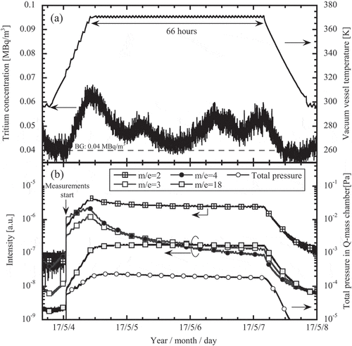
The tritium release amount during wall baking operation was estimated to be about 17.4 MBq, although the deuterium glow discharge cleaning operation was carried out prior to wall baking operation. The average tritium release rate was calculated to be 0.27 MBq/h. The tritium release rate was lower than that of glow discharge cleaning operation, however, the tritium release amount was larger because the baking time became longer. The baking operation becomes one of the effective tritium removal methods in the LHD vacuum vessel.
In the case of wall baking operation, the hydrogen isotope gases or plasma did not present in the vacuum vessel. Therefore, the mechanism of tritium release during wall baking operation is a diffusion process from the bulk in the vacuum vessel.
The chemical forms of released tritium during the LHD plasma experiment and wall conditioning operation are discussed in the next section.
3.1.4. Tritium chemical forms in the exhaust gas
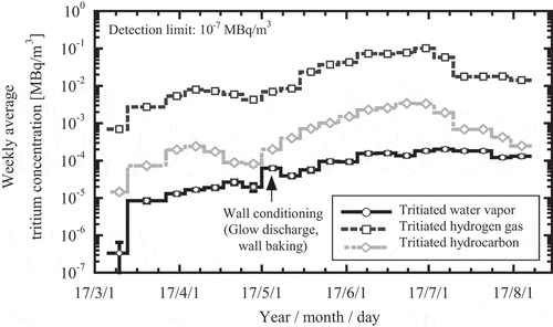
Tritium is one of the hydrogen isotopes and it can form various chemical compounds such as water vapor and hydrocarbons by the plasma surface interactions [Citation23]. Thus, the tritium chemical forms in the exhaust gas should be discriminated in order to the realization of tritium behavior. The water bubbler system installed at the inlet of EDS has the function of the discriminating chemical forms of water vapor, hydrogen gas, and hydrocarbons. shows the weekly average tritium concentration discriminated chemical forms measured by the water bubbler system from March 6th, 2017 to August 21st, 2017. Three chemical forms were observed in the exhaust gas during the whole monitoring period. Since the main operation gas was hydrogen or deuterium gas, tritium in the vacuum vessel become tritiated hydrogen isotope gas and they were major components gas which constituted about 96.4% in the exhausted tritium chemical forms. As the second major gas, the tritiated hydrocarbons were observed and constituted about 3.2% in the exhausted tritium chemical forms. Since the divertor tile as the plasma-facing components in LHD was made of carbons, the chemical forms of hydrocarbons were produced by the chemical sputtering in divertor plasma. Although there was not much data of tritiated hydrocarbons in the exhaust gas, Kaminaga et al. have reported that the ratio of tritiated hydrocarbons in JT-60U made up 4.3% and 6.3% [Citation6]. The ratio of tritiated hydrocarbon in the LHD exhaust gas was about two-thirds of that in JT-60U. The plasma-facing materials in LHD mainly consist of stainless steel as the first wall and a carbon material as a divertor tile. Thus, tritium behavior is supposed to be different from JT-60U based on carbon materials and other fusion test devices. The metal first wall would reduce the tritiated hydrocarbons as the refractory organic matter in the exhaust gas.
Tritiated water vapor was minor chemical forms and constituted about 0.4% because the average dew point in the exhaust gas was less than 253 K which corresponds to the water vapor concentration of 0.1 %. In JT-60U, the range of the ratio of tritiated water vapor in the exhaust gas was from 0.2% to 0.5% [Citation1–4,Citation6]. The ratio of tritiated water vapor in the exhaust gas was almost the same between LHD and JT-60U. It would indicate that the release of tritiated water vapor was the same source between two devices. The vacuum chamber contains water in general. The water would be released from the vacuum vessel during the operation of the plasma experiment and wall conditioning. The hydrogen atom in water in the vacuum chamber would exchange with tritium atom. Thus, the source of tritiated water vapor would be the vacuum vessel.
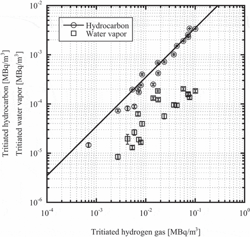
shows the relationships between the concentrations of tritiated hydrocarbons, water vapor, and tritiated hydrogen gas. The concentration of tritiated hydrocarbons was proportion to that of tritiated hydrogen gas. It suggested that a part of produced tritium in core plasma slowed down and transported to the divertor region along with the scrape-off layer. Then the divertor plasma contained tritium reacted with the carbon and tritiated hydrocarbons were generated. Also, tritiated hydrocarbons would be generated by hydrogen or deuterium glow discharge operation. On the other hand, the behavior of tritiated water vapor might not seem to be related to that of tritiated hydrogen gas. The source of tritiated water vapor would be from the metal wall because the vacuum vessel contained a small amount of water in the metal wall. Thus, tritiated water vapor was increased during the long-term wall baking operation. Besides, hydrogen isotopes and oxygen on the stainless steel as the first wall would be spluttered and released by the glow discharge operation. Then the tritiated water vapor was generated via the chemical reaction between hydrogen isotope and oxygen during the glow discharge operation. Therefore, the behaviors of tritiated water vapor would be independent of that of tritiated hydrogen gas.
3.2. Tritium balance in LHD and exhaust pathway of tritium
3.2.1. Tritium exhaust rate from LHD vacuum vessel
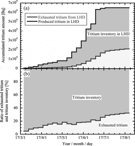
shows the variation of the amount and the ratio of exhausted tritium and tritium inventory in the LHD vacuum vessel during the plasma experiment. The amount of produced tritium was estimated from the results of neutron measurement. The amount of exhausted tritium was measured by a water bubbler system. The tritium exhausted rate, which is defined as the ratio of the exhausted tritium and produced tritium, was 5.1% in the first week and then gradually increased with the progress of the deuterium plasma experiment. It suggested that the produced tritium was implanted in the vacuum vessel and not released from that in the initial phase of the deuterium plasma experiment. As mentioned in 3.1.2, produced tritium has high energy and it is implanted into the deep of few µm. Therefore, implanted tritium would be held in the bulk of plasma-facing materials in the initial phase of the deuterium plasma experiment. Then performing the number of the deuterium plasma experiments and the wall conditioning operations, tritium in the materials would be diffused along with the operation time, and the tritium exhausted rate was gradually increased toward the end of the plasma experiment. The implanted tritium has been continuously released in the H phase. The total amount of exhausted tritium was 32.8% of produced tritium at the end of the plasma experimental campaign. It suggested that two-thirds of produced tritium would be implanted and remained in the vacuum vessel after the first deuterium plasma experimental campaign. Since the tritium inventory was increasing even at the end of the D phase as shown in , it is likely that the tritium inventory in the vacuum vessel is not yet saturated. The tritium inventory in the vacuum vessel is determined by the balance of release, decay, and implantation of tritium. The tritium balance will be continuously observed to evaluate the time it takes for the tritium inventory in the vacuum vessel to reach saturation. Besides, for the investigation of the tritium amount and the distribution of tritium inventory, the analysis of the material samples installed in LHD vacuum vessel has been started [Citation24].
Figure 10. Accumulated tritium amount and the ratio of exhaust and inventory of tritium during the first deuterium plasma experiment
The deuterium plasma experiment has been conducted in various fusion test devices. Some of the large fusion test devices have evaluated the tritium balance in the vacuum vessel. The tritium exhaust rate in JET, JT-60U, and LHD are summarized in . The plasma-facing materials and wall conditions are also indicated in . These data of JET were evaluated in the deuterium plasma phase prior to the Preliminary Tritium Experiment and the Deuterium–Tritium Experiment. In the deuterium plasma experiment in the JET graphite phase, about 20% of tritium was exhausted from the vacuum vessel [Citation8]. On the other hand, the tritium exhausted rate in the beryllium phase of JET became two times larger than that in the carbon phase. In the case of tritium balance in JT-60U which has the carbon-based first wall and divertor tiles, 28% of produced tritium was exhausted and about 50% was retained in the vacuum vessel [Citation2]. In the case of LHD, the tritium exhausted rate was achieved to be 32.8%. The ratio of exhaust tritium during the plasma experiment in LHD was about 1.2 times and 1.6 times larger than that of JT-60U and in the carbon phase of JET, respectively. However, the tritium exhausted rate in LHD was low in comparison with the results of the beryllium phase of JET. The first wall plates in the vacuum vessel of LHD are stainless steel, while graphite plates are used for the divertor. The area of stainless steel is 700 m2 and the graphite area is 30 m2 which constitutes about 5% of the total plasma facing area [Citation22]. Besides, a part of the first wall near the graphite plates would be covered by sputtered carbon as mentioned in the section 3.1.2. Thus, the ratio of the primary metal wall area in LHD would have been reduced by carbon deposition. These results suggest that the larger the ratio of the metal wall as the plasma-facing components in the vacuum vessel, the larger the tritium exhausted rate. It is well-known that the carbon material is sputtered by plasma and the hydrogen isotopes of H, D, and T are incorporated into the carbon redeposition layer [Citation25]. Thus, the tritium inventory in the vacuum vessel increases when the carbon tile is used as the plasma-facing components. It is considered that the metal wall would reduce the tritium inventory by the carbon co-deposition in the vacuum vessel.
3.2.2. Tritium release pathway from LHD vacuum vessel
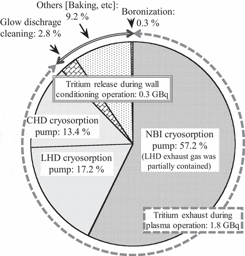
As mentioned in 3.1.1, we could observe the tritium release pathway from LHD. shows the exhausted tritium pathway from the vacuum vessel at the end of the plasma experiment. The NBI cryosorption pumps were the main tritium exhaust pathway during plasma operation and held more than 50% of the total exhausted tritium. Since the NBI is installed evenly over the entire torus vacuum vessel and the NBI cryosorption pump has a high pumping speed, produced tritium in the LHD vacuum vessel would be transported and absorbed in the NBI cryosorption pump via the NBI vacuum ports. On the other hand, the rate of tritium exhaust pathway via the LHD cryosorption pumps as the main vacuum pumping system and the CHD in the vacuum vessel were merely one-third of the total exhausted tritium because they are installed locally in the torus as shown in . The total amount of exhausted tritium via the cryosorption pumps for NBIs, LHD and CHD corresponded to 28.1% (about 1.8 GBq) of produced tritium. Besides, the ratio of tritium released by wall conditioning operation including the He, H2, D2 glow discharge cleaning, the wall baking at 368 K, and the boronization operation was only 4.7% (about 0.3 GBq) of produced tritium thought the total time of wall conditioning operation was more than 1100 hours as summarized in . In the deuterium plasma operation, the implanted tritium in the vacuum vessel is hardly removed by the wall condition operation in the case of LHD.
4. Conclusion
The tritium exhaust behavior and tritium balance in the LHD vacuum vessel were investigated in the first deuterium plasma experiment. The tracer tritium produced by D-D reactions in LHD vacuum vessel revealed that (i) tritium on the surface of the first wall and divertor tiles as plasma facing components was removed by hydrogen isotope exchange reaction and the tritium release from the bulk of the plasma-facing components was the diffusion-limited process, and (ii) about one-third of produced tritium was exhausted from the LHD vacuum vessel during the plasma operation and the large portion of produced tritium was still retained in the LHD vacuum vessel as tritium inventory. The estimation of tritium inventory was necessary to clarify the tritium balance in the LHD.
The tritium exhaust ratio in LHD using the stainless steel as the first wall and the carbon as the divertor tile was larger than that in JT-60U based on the carbon material and less than that in the case of JET using beryllium as the plasma-facing components. Also, the ratio of tritiated hydrocarbons in the exhaust gas of LHD reduced in comparison with the case of JT-60U. Thus, the selection of metal wall would be one of the key factors to control the tritium inventory and to reduce the tritium compounds in the exhaust gas.
Acknowledgments
We are grateful to Prof. N. Akata of Hirosaki University and Ms. C. Iwata of NIFS for their technical supports of tritium measurement. We are also grateful to Dr. K. Ogawa of NIFS for his helpful supports of neutron data.
Disclosure statement
No potential conflict of interest was reported by the authors.
Additional information
Funding
References
- Miya N, Nemoto M, Tohoshima N. Tritium release from JT-60U vacuum vessel following high-power heated deuterium operations. Fusion Technol. 1994;26:507–511.
- Masaki K, Yagyu J, Arai T, et al. Wall conditioning and experience of the carbon-based first wall in JT-60U. Fusion Sci Technol. 2002;42:386–395.
- Kaminaga A, Horikawa T, Nakamura H, et al. Analysis of exhausted gas in JT-60 deuterium operation. Proceedings of 20th IEEE/NPSS Symposium on Fusion Engineering; 2003 Oct 1014; San Diego, (CA). p 144–147.
- Nakamura H, Higashijima S, Isobe K, et al. Application of glow discharges for tritium removal from JT-60U vacuum vessel. Fusion Eng Des. 2004;70:163–173.
- Isobe K, Nakamura H, Kaminaga A, et al. Tritium release behavior from JT-60U vacuum vessel during air exposure phase and wall conditioning phase. Fusion Sci Technol. 2005;48:302–305.
- Kaminaga A, Nakamura H, Isobe K, et al. Exhaust gas monitoring device of nuclear fusion experimental device. Proceedings of Tech 2005; 2005 Mar. 34; Osaka (Japan). [in Japanese, CD-ROM]
- Usselmann E, Hemmerich JL, Holland D, et al. Experimental set-up for gas balance measurement at JET. Vacuum. 1990;41:1515–1518.
- Sartori R, Saibene G, Goodall DHJ, et al. Deuterium release measurements in the Be phase of JET and determination of tritium content in the exhaust gas. J Nucl Mater. 1990;176-177:624–629.
- Dietz KJ, Pick MA, Peacock AT, et al. Beryllium in JET; A report on the operational experience. Proceedings of 13th IEEE/NPSS Symposium on Fusion Engineering; 1989 Oct 26; Knoxville (TN). p. 517–521.
- Taylor PL, Kellman AG, Lee RL. Tritium in the DIII-D carbon tiles. J Fusion Energy. 1993;12:35–40.
- Loarer T, Brosset C, Bucalossi J, et al. Gas balance and fuel retention in fusion devices. Nucl Fusion. 2007;47:1112–1120.
- Osakabe M, Isobe M, Tanaka M, et al. Preparation and commissioning for the LHD deuterium experiment. IEEE Trans Plasma Sci. 2018;46:2324–2331.
- Takeiri Y. The large helical device: entering deuterium experiment phase toward steady-state helical fusion reactor based on achievements in hydrogen experiment phase. IEEE Trans Plasma Sci. 2018;46:2348–2353.
- Tanaka M, Suzuki N, Kato H, et al. Design and commissioning of the exhaust detritiation system for the large helical device. Fusion Eng Des. 2018;127:275–283.
- Murase T, Motojima G, Tanaka H, et al. Development of new concept in-vessel cryo-sorption pump for LHD closed helical divertor. Plasma Fusion Res. 2016;11:1205030.
- Tanaka M, Kato H, Suzuki N, et al. Determination of tritium activity and chemical forms in the exhaust gas from a large fusion test device. J Radioanal Nucl Chem. 2018;318:877–886.
- Isobe M, Ogawa K, Nishitani T, et al. Neutron diagnostics in the large helical device. IEEE Trans Plasma Sci. 2018;46:2050–2058.
- Isobe M, Ogawa K, Nishitani T, et al. Fusion neutron production with deuterium neutral beam injection and enhancement of energetic particle physics study in the large helical device. Nucl Fusion. 2018;58:082004.
- Friedrich M, Sun G, Grötzschel R, et al. Tritium depth profiling in carbon by accelerator mass spectrometry. Nucl Instr Meth B. 1997;123:410–413.
- Sun GY, Friedrich M, Grötzschel R, et al. Quantitative AMS depth profiling of the hydrogen isotopes collected in graphite divertor and wall tiles of the tokamak ASDEX-Upgrade. J Nucl Mater. 1997;246:9–16.
- Tokitani M, Masuzaki S, Yoshida N, et al. Evaluation of the surface morphologies and erosion/deposition profiles on the LHD first-wall by using toroidal array probes. J Nucl Mater. 2013;442:S873–S879.
- Motojima G, Yoshida N, Murase T, et al. Preliminary examination of reflection coefficient measurement of RGB lights on the first wall in LHD. Plasma Fusion Res. 2015;10:1202074.
- Roth J. Nuclear fusion research: understanding plasma-surface interactions. In: Clark REH, Reiter D, editors. Chapter 9, Review and status of physical sputtering and chemical erosion of plasma facing materials. Berlin, Heidelberg: Springer; 2005. p. 203–224.
- Masuzaki S, Otsuka T, Ogawa K, et al. Investigation of remaining tritium in the LHD vacuum vessel after the first deuterium experimental campaign. Phys Scr. 2020;T171:014068.
- Haasz AA, Davis JW. Nuclear fusion research: understanding plasma-surface interactions. In: Clark REH, Reiter D, editors. Chapter 10, Hydrogen retention in and release from carbon materials. Berlin, Heidelberg: Springer; 2005. p. 225–248.

