
 ?Mathematical formulae have been encoded as MathML and are displayed in this HTML version using MathJax in order to improve their display. Uncheck the box to turn MathJax off. This feature requires Javascript. Click on a formula to zoom.
ABSTRACT
Thick corrosion oxide (Fe3O4) layers containing radioactive metals are generated in a carbon steel heat transport system (HTS) of pressurized heavy water reactors during operation. It is necessary to decontaminate the oxide layers to reduce radiation exposure to workers before maintenance and decommissioning. Since the oxide layer thickness in the HTS is about 75 μm, a considerable amounts of secondary wastes can be generated when the existing decontamination processes are applied. The aim of this study is to design a chemical decontamination process using chelate-free inorganic acid that can be effectively applied to remove the oxide layers in the HTS and to minimize the secondary waste generation. Therefore, Fe3O4 dissolution behaviors were evaluated in a Hydrazine Based Reductive metal Ion Decontamination (HyBRID) process using the chelate-free inorganic acid. From this result, the decontamination process of oxide layers in the HTS using recycling of decontamination process solution and the process control method using pH monitoring were constructed. In particular, process control based on pH monitoring can be easily used because decontamination performance can be controlled according to the goal; (1) effective removing the oxide layer at decommissioning, (2) avoiding corrosion of base metal and removing the oxide layer at maintenance.
1. Introduction
During the operation of the pressurized heavy water reactor (PHWR), the carbon steel heat transport system (HTS) undergoes corrosion due to its high temperature and high pressure conditions [Citation1]. The corrosion products are transported to the reactor core through the coolant where they are activated by neutrons [Citation2]. These activated corrosion products circulate in the reactor coolant system and form Fe3O4 oxide layers after being deposited on the carbon steel HTS component surface [Citation3]. These oxide layers, including radioactive metals, build up the radiation field [Citation4]. Thus, the oxide layers need to be decontaminated to reduce radiation exposure to workers before maintenance or decommissioning of the PHWR [Citation5–7].
In order to decontaminate the Fe3O4 oxide layer in the PHWR, the reductive decontamination processes such as CAN-DECON, CAN-DEREM, and CAN-DEREM Plus using organic acids have been used [Citation7,Citation8]. The wastewater of these decontamination processes includes activated corrosion products, and they can be removed by ion exchange resins during the treatment [Citation8–10]. For this reason, a considerable amounts of the radioactive ion exchange resins included in the hard-to-treat waste are generated from the processes as the secondary wastes [Citation10]. To solve this problem, the Korea Atomic Energy Research Institute (KAERI) has been developing a HyBRID (Hydrazine Based Reductive metal Ion Decontamination process) process [Citation11]. The HyBRID process is a new reductive decontamination process that removes the Fe-rich oxide layers in the reactor coolant system of a pressurized water reactor (PWR) with a chelate-free inorganic acid [Citation11–13]. The decontamination performance of the HyBRID process to the Fe-rich oxide layers of PWR is similar to commercial process developed [Citation11]. The HyBRID process can also be applied to the decontamination of the Fe3O4 oxide layer in the PHWR. However, decontamination performance of the HyBRID process can decrease during decontamination of thick Fe3O4 oxide layers in the PHWR. Because the oxide layer thickness of the PHWR is about 75 μm, which is much thicker than that of about 2–3 μm in the PWR [Citation14]. In particular, the concentration of Fe ions contained in the 3 μm of the Fe3O4 oxide layer calculated based on the result of decontamination in Maine Yankee, which is the PWR, is 50 ppm [Citation15]. From this result, it is considered that the concentration of Fe ions contained in the 75 μm of the Fe3O4 oxide layer in the PHWR is 1250 ppm, which is much higher than the concentration in the PWR. The high concentration of Fe ions dissolved in the decontamination process solution can be redeposited in the shape of Fe3O4 and can interrupt the Fe3O4 dissolution reactions [Citation16]. For this reason, the spent HyBRID process solution should be frequently replaced if the existing HyBRID process solution for the PWR decontamination is applied to the PHWR. However, frequent discharging and charging of the process solution increase radioactive wastes and decrease the in-site applicability.
Therefore, a decontamination method for the carbon steel HTS in the PHWR by recycling the HyBRID process solution without any replacement of process solution was studied in this paper. First, the dissolution behaviors of the Fe3O4 in the carbon steel HTS in the PHWR were investigated under the condition of existing HyBRID process solution for PWR decontamination. The recycling condition of spent HyBRID process solution was derived by conducting a Fe removal test of the spent process solution surrogate. Additionally, the decontamination process and process control method using pH monitoring were designed to remove the oxide layers in the carbon steel HTS in the PHWR. Finally, the decontamination performance of the constructed process was evaluated by performing the dissolution test of the simulated oxides in the carbon steel HTS in the PHWR.
2. Experimental methods
2.1. Materials
N2H4·H2O (98%, Junsei, Japan), H2SO4 (97%, Showa, Japan), CuSO4 (97.5, Junsei, Japan) was used to prepare a HyBRID process solution. In order to simulate the Fe3O4 oxide layer, the Fe3O4 powders (94%, Junsei, Japan) was used. FeSO4 · 7H2O (99%, Sigma-Aldrich, USA) was used to simulate the Fe ions in a spent HyBRID process solution. Ba(OH)2 (98%, Junsei, Japan) was used to recycling the spent HyBRID process solution. All solutions were prepared using deionized water (18 MΩ·cm), which was generated by Millipore Direct-Q UV (Merck Millipore Co., USA).
2.2. Dissolution of Fe3O4
A dissolution test of Fe3O4 was performed using existing HyBRID process solution developed to dissolve the Fe-rich oxide layers in the PWR. The existing HyBRID process solution consisted of 50 mM of N2H4·H2O, 27 mM of H2SO4, and 0.5 mM of CuSO4. The pH was adjusted to 2.75. 7.94 mM, 5.40 mM, 2.86 mM, and 1.59 mM of Fe3O4 powders were added in the existing HyBRID solution to simulate the 1250 ppm, 850 ppm, 450 ppm, and 250 ppm of Fe ions contained in Fe3O4 oxide layers, respectively. All solutions were prepared in a volume of 200 mL in polypropylene wide-mouth bottles. The dissolution test of the Fe3O4 was conducted for 7 h maintaining the 95°C of temperature. The solutions were mixed at 200 rpm in a water bath (Julabo, SW22). During the dissolution test, the samples of solutions were taken during the test at 10, 25, and 40 min, and 1, 2, 3, 4, 5, 6, and 7 h.
2.3. Recycling test of spent HyBRID process solution
A recycling test of spent HyBRID process solution surrogate was conducted to remove the Fe ions. shows the compositions and pHs of an initial HyBRID process solution and a spent process solution. The condition of the initial process solution follows the existing HyBRID process solution for the decontamination of the PWR [Citation11]. The condition of the spent process solution was obtained by dissolution tests of Fe3O4 in the initial process solution. Generally, most of the Fe3O4 was dissolved in a form of Fe2+ ions due to the conversion of Fe3+ to Fe2+ [Citation17,Citation18]. When 2.22 mM of Fe3O4 was injected into the initial process solution, the concentration of dissolved Fe2+ ions was about 350 ppm during the 5 h dissolution test. Therefore, the spent process solution surrogate was prepared in a 200 mL glass beaker using 50 mM of N2H4•H2O, 27 mM of H2SO4, 0.5 mM of CuSO4, and 6.3 mM FeSO4•7H2O. The recycling test consisted of a precipitation, a filtration, and a make-up steps. First, the precipitation step was conducted by injecting Ba(OH)2 to remove the Fe ions in the spent process solution surrogate. The molar ratio (R) of Ba(OH)2 over SO42- in the surrogate was changed within a range of 0.40 to 0.70. During injecting Ba(OH)2, the surrogate was stirred at 150 rpm by using a magnetic stirrer (MTOPS, HSD 150–03P). After completing the injection of Ba(OH)2, stirring was continuously performed for 10 min. The surrogate was then filtered using a 0.45 μm pore syringe filter in the filtration step to recover the purified solution. In the make-up step, 15.7 mM of N2H4·H2O and 0.5 mM of CuSO4 were injected the purified solution, and H2SO4 was added into purified solution for adjusting the pH condition of purified solution to initial pH condition, 2.75.
Table 1. Chemical compositions and pHs of the initial HyBRID process solution and spent process solution
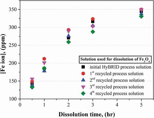
In order to confirm the performance of recycled process solution, dissolution tests of Fe3O4 were conducted. Before conducting the dissolution test using the recycled process solution, the dissolution test of 2.22 mM of Fe3O4 was carried out using the initial process solution for 5 h at 95°C with mixing at 200 rpm in the water bath. The solution was prepared in 1 L of polypropylene wide-mouth bottle. After the dissolution test using initial process solution was completed, the spent process solution became same condition as the initial process solution through recycling process including the precipitation, filtration, and make-up steps. Then, the dissolution tests using the recycled process solution were repetitively conducted four times under the same condition with the dissolution test using the initial process solution. During the dissolution tests, the samples of the solutions were taken, and the sampling time was 0.5, 1, 2, 3, and 5 hr.
2.4. Dissolution test of Fe3O4 using HyBRID process solution for PHWR
The decontamination test of simulated corrosion oxides was conducted using a decontamination process what we set up in this study. The decontamination step was performed by using 1 L of the initial HyBRID process solution. The initial process solution was prepared in the polypropylene bottle using 50 mM of N2H4·H2O, 27 mM of H2SO4, and 0.5 mM of CuSO4. The pH of process solution was 2.75. In the process solution, 7.94 mM of Fe3O4 was injected to simulate the Fe3O4 layers existed in the HTS of the PHWR. The decontamination step was conducted in the water bath at 95°C, and the process solution was mixed at 200 rpm. The pH of the solution was measured during performing the decontamination step. The decontamination step was finished when the pH was reached 3.0 after pH fluctuation. After the decontamination step was completed, a recycling process was applied to return the condition of spent process solution to that of initial process solution. In the precipitation step, 16.5 mM of Ba(OH)2 was injected to remove the Fe2+ ions dissolved in the spent process solution. During injecting the Ba(OH)2 the spent process solution was mixed at 150 rpm using the magnetic stirrer, and the stirring was continued for 10 min. In the filtration step, the precipitates including BaSO4, Cu(OH)2 and Fe(OH)2 were filtered by paper filter with 2.5 μm pore size. In the make-up step, 15.7 mM of N2H4·H2O was re-injected into the purified solution. The pH of the purified solution was adjusted 2.75 by adding the H2SO4. The pH was monitored as H2SO4 was added. After putting the H2SO4 in the purified solution, 0.5 mM of CuSO4 was injected. The decontamination step and the recycling process were iteratively carried out again using recycled process solution until the all the Fe3O4 remained in the solution was dissolved.
2.5. Analysis
The concentrations of Fe ions in the solution were measured by using atomic absorption spectroscopy (Perkin Elmer, AAnalyst 400). The UV spectrometer (Hach co. DR5000) was used to analyze the concentrations of chemical species of hydrazine. The pH was measured by using pH meter (Thermo scientificTM, Orion Versa Star ProTM pH/ISE Benchtop Multiparameter Meter).
3. Results and discussion
3.1. Dissolution behaviors of Fe3O4 in HyBRID process solution
The results of Fe3O4 dissolution in the existing HyBRID process solution are shown in ). It was confirmed that all Fe3O4 were dissolved into Fe ions within 2–3 h or 4–5 h when the initial Fe ions in the injected Fe3O4 were 250 ppm or 450 ppm, respectively. When the Fe ions in the injected Fe3O4 were 850 ppm or 1250 ppm, the concentrations of Fe ions dissolved for 5 hrs were 550 ppm. After the 5 h dissolution test, the concentrations of Fe ions dissolved were constant though the dissolution times increased. The dissolution rate calculated based on the results of Fe3O4 dissolution are indicated in ). The dissolution rate was the highest when the dissolution was started regardless of the amount of Fe3O4 injected. In particular, the initial dissolution rate was higher when the amount of Fe3O4 was injected increased. It is considered to be caused by an increase in the cross-section of the Fe3O4 that can react with the process solution as the amount of Fe3O4 injected increased. The dissolution rates decreased rapidly under all test conditions, however, the dissolution rates increased again within 1–2 h. Finally, the dissolution rates decreased to 0 when the concentration of Fe ions dissolved in the HyBRID process solution was constant.
Figure 1. The changes in (a) concentration of dissolved Fe ions; (b) dissolution rate of magnetite; (c) pH; (d) concentration of chemical species of hydrazine during dissolution in the existing HyBRID process solution.
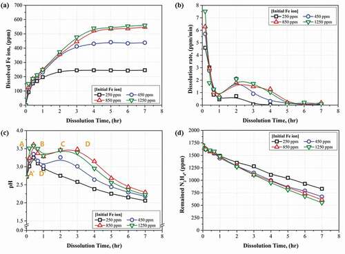
The changes in the pH during the dissolution test are shown in ). When the concentration of Fe ions in the Fe3O4 injected was 250 ppm, the pH increased and decreased immediately. When the concentrations were from 450 ppm to 1250 ppm, the pH increased, decreased, increased again, and finally decreased. In addition, the pH decreased slowly when the concentration of Fe ions was higher.
It is considered that the changes in the pH were caused by the dissolution reaction of the Fe3O4 in the process solution. The dissolution reaction at 95°C was calculated using software (HSC-Chemistry 9.0) and written in EquationEquations (1)(1)
(1) –Equation(3)
(3)
(3) . The dissolution of the Fe3O4 are carried out by an acidic dissolution reaction and a reductive dissolution reaction. In acidic dissolution, Fe3O4 is dissolved into Fe3+ ion and Fe2+ ion, and H+ ions are consumed as represented in EquationEquation (1)
(1)
(1) . The acidic dissolution causes an increase in pH by consuming H+ ions.
In the reductive dissolution, N2H5+ ion which is the chemical form of N2H4 under acidic condition participates in the dissolution reaction of Fe3O4 as shown in EquationEquations (2)(2)
(2) and (Equation3
(3)
(3) ). The Fe3O4 is dissolved into the Fe2+ ion by reacting with Cu+ ion in the process solution. The Cu2+ ion generated from the reductive dissolution reaction is reduced to Cu+ ion by reacting with N2H5+ ion. Although the N2H5+ is consumed in this reaction, the pH will be increased because a large number of H+ ions are consumed during the reaction.
Finally, Fe3+ reduction reaction occurs when the Fe3+ ions exist in the process solution. This reaction was calculated using software (HSC-Chemistry 9.0) at 95°C. As shown in EquationEquation (4)(4)
(4) , the Fe3+ ions are reduced to Fe2+ ions through reaction with N2H5+. The Fe3+ reduction reaction causes a decrease in pH due to the consumption of N2H5+ ion and generation of H+ ions.
Based on the above dissolution reactions, the tendency of pH change during the Fe3O4 dissolution can be explained by dividing it into four sections, from A to D, or by dividing it into two sections, A’ and D’, as illustrated in ). In sections A and A’, pH of the process solution increased. As shown in the , the dissolution rate was the highest in sections A and A’. From this result, it was predicted that H+ ions were rapidly consumed in sections A and A’ due to the acidic dissolution and reductive dissolution reactions of Fe3O4.
The section B was the section where the pH decreased. In this section, it is considered that the reduction reaction of the Fe3+ ion generated by acidic dissolution occurred dominantly. This pH decrease was caused by the difference of ΔG value between Fe3+ reduction and dissolution reaction. As shown in EquationEquations (1)(1)
(1) –Equation(3)
(3)
(3) , the ΔG value of the Fe3+ reduction is lower than that of acidic and reductive dissolution reactions. In section B, the consumption of the N2H5+ ions and gain of the H+ ions during Fe3+ reduction reaction caused the decrease in pH.
In section C, pH increased again. The concentration of Fe3+ ions decreased by Fe3+ reduction reaction in section B, therefore, acidic and reductive dissolution reactions became dominant again in section C. It was confirmed that the dissolution rate increased again in section C as shown in ). Additionally, B and C sections were more prominent as the amount of Fe3O4 injected increased as indicated in ). The highest pH value during the dissolution was higher when the amount of Fe3O4 injected increased. From these results, it was known that the dominances of the dissolution reaction and Fe3+ reduction reaction were changed during dissolution. Because the dissolution reactions represented in EquationEquations (1)(1)
(1) and (Equation2
(2)
(2) ) occurred more, and the amount of H+ consumed increased when the amount of Fe3O4 increased.
The sections D and D’ were the sections where the pH decreased again. In this section, the Fe3+ reduction reaction became dominantly, and Fe3O4 dissolution reactions decreased. Because the concentration of Fe ions in the HyBRID process solution reached the limitation. This result agreed well with the dissolution rate as found in ). The dissolution rate was converged to 0 in section D due to the completion of the Fe3O4 dissolution. Moreover, in this section, the concentration of the chemical species of hydrazine decreased continuously though the dissolution rate was 0 as indicated in ). It was caused by the consumption of the N2H5+ ions during Fe3+ reduction reaction as shown in EquationEquation (4)(4)
(4) . From these results, it was found that section D is appeared slowly when the concentration of Fe ions is higher because the dissolution reactions of Fe3O4 shown in EquationEquations (1)
(1)
(1) and (Equation2
(2)
(2) ) occur for a long time.
3.2. Fe removal in the spent process solution
From the results of Fe3O4 dissolution test using the existing HyBRID process solution, it is confirmed that 1250 ppm of Fe ions containing in the Fe3O4 in the carbon steel HTS in the PHWR cannot be dissolved at once. Therefore, the Fe3O4 in the carbon steel HTS needs to be removed by 3–4 times of repetitive decontamination. In order to apply the repetitive decontamination to the thick corrosion oxide layer, it is effective to reuse the spent HyBRID process solution after reducing the spent process solution to initial condition of HyBRID process solution. This can also be useful to minimize the amounts of secondary wastes. When the decontamination performance of the process solution rapidly decreased, reducing the spent process solution to initial condition of process solution can be performed by removing the Fe ions from the spent process solution. In the spent process solution, the Fe ions exist in the form of Fe2+ ions through the Fe3+ reduction reaction as indicated in EquationEquation (4)(4)
(4) . It is well known that the Fe2+ ions can be precipitated into the form of Fe(OH)2 over pH 8 [Citation19]. In particular, the Fe2+ ions in H2SO4 solution can be removed by the reaction with Ba(OH)2 as shown in EquationEquation (5)
(5)
(5) [Citation14]. Therefore, the solution is possible to be reduced to initial condition of HyBRID process solution by filtering the precipitates such as Fe(OH)2 and BaSO4 and re-injecting the consumed composition.
Before conducting the Fe removal test from the spent process solution surrogate, an equilibrium calculation of the Fe2+ ion precipitation in the spent process solution by the reaction with Ba(OH)2 was performed using software (HSC-Chemistry 9.0). The chemical composition of the spent process solution was determined based on the . In the equilibrium test, molar ratio (R) of added Ba(OH)2 to the SO42- ions in the spent process solution surrogate changed from 0 to 1. shows the results of the equilibrium calculation. Fe2+ ions began to convert into Fe(OH)2 when the R was about 0.15. The conversion was completed when R reached about 0.4. From this result, it seems that Fe2+ ion can be easily converted into Fe(OH)2 by the reaction with Ba(OH)2. The conversion of Cu2+ ions into Cu(OH)2 began when R was about 0.10, and it was completed when the R reached 0.15. The precipitation reaction of Cu2+ ion can be seen in EquationEquation (6)(6)
(6) [Citation14]. Through these conversion reactions shown in EquationEquation (5)
(5)
(5) and EquationEquation (6)
(6)
(6) , it was found that Cu2+ ion converted into Cu(OH)2 before Fe2+ ion converted into Fe(OH)2 during the injection of Ba(OH)2 in the spent process solution. Not only the concentrations of metal ions but also the concentration of SO42- ions decreased with an increase in R through the reaction between SO42- ions with Ba2+ ions. The BaSO4 increased at the same time.
Figure 2. Results of equilibrium calculations on the precipitation step in the recycling process using Ba(OH)2.
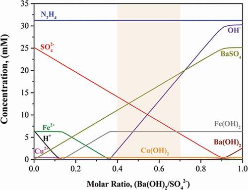
However, the concentration of N2H4 was expected to be maintained. It means that the reaction between N2H4 and Ba(OH)2 did not occur. According to , the concentration of OH− ions gradually increased with an increase in the R. The increase in OH− ions can cause an increase in pH in the surrogate.
Based on these results, it was thought that R should be more than 0.4 to remove the Fe2+ ions completely from the spent process solution. It is necessary to consider the amount of secondary waste generation when R is determined. For this reason, the R for the recycling test was determined to be from 0.40 to 0.70.
The Fe removal test was carried out to derive the conditions for reducing the spent process solution to the initial condition of process solution when the R ranges from 0.40 to 0.70. shows the pH and the concentrations of Fe2+, Cu2+, SO42- ions, and N2H4 in the purified process solution obtained by adding the Ba(OH)2 for precipitation and performing the filtration. As shown in , Fe2+ ions were removed and they were remained below 1 ppm when the R was more than 0.5. Almost all of the Cu2+ ions were removed from the spent process solution in the condition of this test. SO42- ions were removed according to the chemical equivalent, as shown in EquationEquation (6)(6)
(6) . The concentration of N2H4 was constant, although the amount of Ba(OH)2 changed. All of these concentration results agreed well with the result of the equilibrium calculation. In this test, the pH increased from 8.0 to 9.3 when the R changed from 0.40 to 0.70, and this was caused by the increase in OH− ions.
Table 2. Concentrations of metal ions and pH in the purified process solution after the precipitation and filtration steps
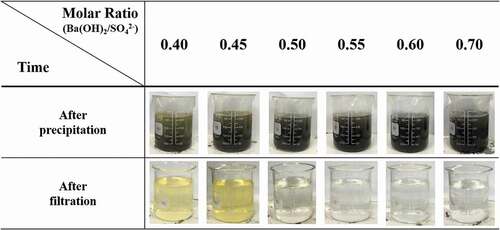
shows the color changes of purified process solutions after the precipitation and filtration. After the precipitation, the solutions had light yellow colors that gradually disappeared as R increased from 0.40 to 0.50. Moreover, the solutions seemed to become darker when R increased from 0.55 to 0.70. The colors of the purified solutions after filtration were similar to those of the solutions after precipitation. The yellow colors gradually disappeared when R increased from 0.40 to 0.50. When R changed from 0.55 to 0.70, the solutions became transparent. These results may have been caused by the nucleation reaction of the particle formation. Fewer nucleation reactions of the particles occurred when the pH of the solution was lower [Citation20]. In this study, it seemed that the nucleation reaction of the Fe(OH)2 formation decreased when the pH was from 8.0 to 8.3, when R was from 0.40 to 0.50. Therefore, Fe(OH)2 can exist in the form of very fine size particles which is smaller than the filterable size, 0.45 μm, when R was 0.40 to 0.50. These fine Fe(OH)2 particles were not expected to be filtered from the solution and cause the solutions to appear yellow. Based on these results, it was determined that R needs to be 0.55 to 0.70 for the nucleation reaction of Fe(OH)2 to effectively occur in the precipitate step.
Figure 3. Changes in the colors of the solutions during the recycling with changes in the molar ratio of Ba(OH)2/SO42−.
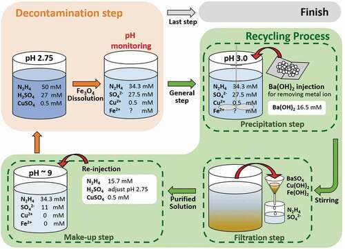
In order to reduce the purified solution to the initial condition of process solution, the chemical compositions, consumed during decontamination or removed during precipitation and filtration, are necessary to be re-injected. Therefore, the make-up test of the chemical composition was carried out. The amounts of chemical compositions injected were calculated by comparing the compositions in the purified solution with that in the initial process solution as indicated in . The results of the calculation are shown in . The purified solutions in which the Fe(OH)2 particles were completely removed were used in this step (R = 0.55 − 0.70). shows the injected amount of decontamination reagents for reducing the purified process solution to the initial condition of process solution. 600 ppm of N2H4, which was consumed during dissolving the 350 ppm of Fe2+ ions in the Fe3O4, is needed to be injected into the purified process solution. The injection amounts of H2SO4 were in proportion to the R. Additionally, 31.8 ppm of Cu2+, which was removed during the precipitation, should be injected into the purified process solution. After the make-up test, the pH range of the reduced solution was 2.68 to 2.76. These pH values of the reduced solution were similar to those of the initial condition of process solution, 2.75. Based on this result, it was verified that the spent process solution was perfectly reduced to the initial condition when the R ranged from 0.55 to 0.70. When the spent process solution is recycled, the lowest possible amount of Ba(OH)2 needs to be injected considering the amount of radioactive waste generation. For this reason, the R was determined to be 0.6 for the effective removal of Fe2+ ions and the reduction of radioactive waste. Based on these results, the recycling process of the spent process solution for decontamination of the carbon steel HTS in the PHWR was designed, and it is shown in . The recycling process is performed after finishing the decontamination step. The recycling process is composed with the precipitation, filtration, and make-up steps. When the decontamination performance of the process solution reached to limitation, Ba(OH)2 is injected into the spent process solution in proportion to the concentration of SO4− ions to convert the Fe2+ ions into Fe(OH)2 in the precipitation step. In the filtration step, the precipitates are removed from the solution using filter. In the make-up step, the consumed composition and removed compositions are re-injected into the purified solution for reducing the spent process solution to the initial condition of process solution.
Table 3. Injection amount of decontamination reagents for reducing the purified to the initial condition
Figure 4. Process flow diagram of the PHWR decontamination using the recycled HyBRID solution.
In order to confirm the Fe3O4 dissolution performance using recycled process solution, Fe3O4 dissolution test was carried out. Before using recycled process solution, Fe3O4 dissolution test was conducted using initial HyBRID process solution. As shown in , the injected Fe3O4 was rapidly dissolved in 2 h. However, the dissolution rate decreased significantly after 2 h. The injected Fe3O4 was completely dissolved in the process solution at 5 h. This tendency was also observed when the dissolution test was performed using the recycled process solution. The differences in the Fe2+ ion concentration of the recycled process solution from that of the initial process solution were within 10%. This result means that the spent process solution can be reduced to the initial condition of process solution through the recycling process consisting of precipitation, filtration, and make-up steps, and the performance of the recycled process solution is similar to that of the initial process solution. From this result, it was verified that HyBRID process solution can be infinitely and repeatedly used after removing the dissolved Fe2+ ions from the spent process solution and adjusting to the initial condition. Moreover, the radioactive waste generated from the decontamination process using this recycling method can be reduced by 40% compared to that generated from the existing HyBRID process. Because the 40% of H2SO4 can be reused when the recycled process solution is applied. Thus, this recycling method of the spent HyBRID process solution can be effectively utilized to decontaminate the carbon steel HTS in the PHWR.
Figure 5. Comparison of Fe ion concentration after dissolution of Fe3O4 using initial HyBRID process solution and the recycled process solution.
3.3. Control of the decontamination process using pH monitoring
As mentioned above, the existing HyBRID process solution for decontamination of reactor coolant system of the PWR can be applied to decontaminate the oxide layers in the carbon steel HTS of the PHWR by combining with recycling process including the precipitation, filtration, and make-up steps. The concept of the PHWR decontamination process using the existing HyBRID process solution is to remove the thick oxide layer by applying the repetitive dissolution using the spent process solution after recycling. Therefore, it is necessary to decide the efficient end point of the decontamination step, where the concentration of dissolved Fe ion becomes constant and the reaction rate becomes 0, and to recycle the spent HyBRID process solution during the PHWR decontamination process.
From the results of Fe3O4 dissolution test using existing HyBRID process solution, it was confirmed the dissolution behaviors were related to the change in pH. As can be seen in , the concentrations of Fe ions in the process solution became constant regardless of the amount of Fe3O4 injected when the pH of the solution reached pH of the initial process solution, 2.75. When more than 300 ppm of Fe ions was dissolved in the process solution, the pH repeatedly increased or decreased at the initial of the dissolution test. However, the pH was not below 2.75 at this time. After this pH fluctuation, pH of the process solution decreased to the initial pH, 2.75. When less than 300 ppm of Fe ions were dissolved in the process solution, the pH decreased immediately after once increase, and the pH reached the initial pH, 2.75. Additionally, the dissolution rate converged to 0 when the pH of the process solution decreased to the 2.75 regardless of the concentration of Fe ions in the process solution. Therefore, it is possible to judge that the decontamination step is finished when the pH reaches 2.75 after some pH variation. Considering the dissolution efficiency, the decontamination step can be finished when the pH decreases to 3.0 after some pH variation. Because the dissolution rates rapidly decrease when the pH decreased to about 3.0 after the pH fluctuation as shown in .
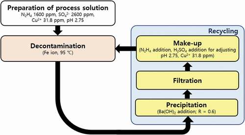
Based on these results, the decontamination process combining pH monitoring method of the carbon steel HTS in the PHWR was designed as shown in . In the preparation step, the decontamination process solution is prepared using the composition of existing HyBRID process solution as listed in . After that, the decontamination step is applied at 95°C. The dissolution of Fe3O4 in the carbon steel HTS is carried out in the decontamination step. During this step, the pH monitoring method can be used to monitor the decontamination status and to determine the end point of the each decontamination step. In the general decontamination step, the dissolution rate can be rapidly decreased when the pH decreases to 3.0 after pH fluctuation. Therefore, the decontamination step is necessary to be ended when the pH reaches 3.0, and the spent process solution needs to be recycled. The recycling process is conducted after every decontamination steps except for the final decontamination step. The recycling process consists of the precipitation step, the filtration step, and the make-up step as represented in . In particular, 15.7 mM of N2H4 is re-injected in the make-up step because 31.3−15.7 mM (1000−1100 ppm) of N2H4 can be consumed when the pH of process solution reaches 3.0 as shown in . This once decontamination step and the once recycling process are included in one decontamination cycle. After finishing one decontamination cycle, the next decontamination cycle is repeatedly carried out consisting of the decontamination step using recycled process solution and recycling process. However, the final decontamination process is performed when the remaining concentration of Fe ions containing Fe3O4 is below 300 ppm. The final decontamination step can be confirmed through the immediate decrease in the pH without pH fluctuation after increase in pH as shown in . The end point of final decontamination step differs depending on the decontamination purpose. When the decontamination process is applied during maintenance of the PHWR, the final decontamination step needs to be stopped when the pH decreases to 3.0 after pH fluctuation. Because it is necessary to prevent corrosion of the base metal due to the long times of decontamination although the Fe3O4 remained in the carbon steel HTS. When the decontamination process is applied before the decommissioning of the PHWR, the decontamination step has to be finished when the pH decreases to 2.75 after pH fluctuation. Because it is important to remove radionuclides with oxide layers as much as possible before decommissioning, and the corrosion of the base metal is not significant issue during the decommissioning. After the final decontamination step, the recycling process is not conducted.
Figure 6. Scheme of the decontamination process of the heat transfer system in the PHWR including recycling process and pH monitoring method.
3.4. Performance of the decontamination process
The Fe3O4 dissolution performance of decontamination process using pH monitoring method was evaluated by conducting the repetitive decontamination step and recycling process including the precipitation, filtration, and make-up steps. The Fe3O4 containing 1250 ppm of Fe ions were used for the dissolution test to simulate the 75 μm of oxide layer in the carbon steel HTS of the PHWR. In this case, we assumed the object of the decontamination was decommissioning of PHWR. For this reason, the pH had to be monitored during the general decontamination step until reaching 3.0, and the final decontamination step needed to be finished when the pH below 2.75. The result of repetitive dissolution test is indicated in . The Fe3O4 added in the HyBRID process solution was completely dissolved through the 3 cycles of decontamination including 3 times of decontamination step and 2 times of recycling process.
Figure 7. Result of simulated magnetite dissolution test using HyBRID decontamination process for PHWR and monitoring method.
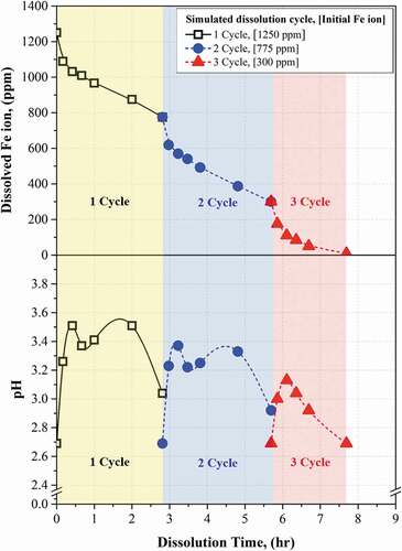
In the 1st cycle, the pH changed as 2.70 → 3.26 → 3.51 → 3.37 → 3.41 → 3.51 → 3.04 during the decontamination step. It was confirmed that the pH increased, decreased, increased again, and decreased again as shown in the . According to the monitoring method, the decontamination step was stopped when the pH reached 3.04. The time taken to reach pH 3.04 was 2.8 hrs. At this time, 475 ppm of Fe ions were dissolved in the HyBRID solution. This result was similar with the result of dissolution test indicated in . After the dissolution step, the recycling process was applied by carrying out the precipitation, filtration, and make-up steps.
In the 2nd cycle, the Fe3O4 remained after finishing the 1st dissolution step, which is containing 775 ppm of Fe ions, was dissolved in the recycled HyBRID solution. The pH changed as 2.69 → 3.23 → 3.37 → 3.22 → 3.25 → 3.33 → 2.92. This trend was similar to the 1st cycle. However, the highest pH at the 2nd cycle was lower than the highest pH at the 1st cycle. This phenomenon agreed well with the result of the dissolution test shown in . This result means that the dissolution reaction was decreased because the amount of Fe3O4 remained in the process solution at the 2nd cycle was lower than that at the 1st cycle. When the pH reached 2.92, the time took 2.9 hrs, and 475 ppm of Fe ions were dissolved in the solution. The spent HyBRID process solution was recycled by the recycled process.
In the 3rd cycle, the Fe3O4 remained after finishing the 2nd dissolution step was dissolved in the recycled HyBRID process solution. The Fe3O4 remained was expected to contain 300 ppm of Fe ion, and the 3rd cycle was considered as final decontamination step. The pH increased and directly decreased as 2.70 → 3.00 → 3.13 → 3.04 → 2.92 → 2.69, and this trend was different with 1st or 2nd cycles. Because the amount of Fe3O4 remained was small, and this caused that the dissolution reaction of Fe3O4 was finished rapidly. The final cycle was finished when the pH reached 2.69. At this time, 292 ppm of Fe ions was dissolved in the process solution. The 8 ppm of remaining Fe3O4 was expected to be completely dissolved by applying short time of decontamination step according to the results of Fe3O4 dissolution test shown in . From this result, it was confirmed that the Fe3O4 containing 1250 ppm of Fe ions was effectively dissolved by three times decontamination step and two times recycling step. In addition, it was verified that pH monitoring method is useful to decide the time to stop the decontamination step.
4. Conclusion
In this research, the chemical decontamination process for removing the corrosion oxide layer in the carbon steel heat transport system of the PHWR was studied. The existing HyBRID process solution developed to decontaminate the PWR is used in a PHWR decontamination process consisting of decontamination step and recycling process. During decontamination step, pH monitoring method is applied to control the step and confirm the end point. The recycling process is conducted to reduce the spent HyBRID process solution to the initial condition of HyBRID process solution. The recycling process consists of precipitation, filtration, and make-up steps. The reduced process solution is reused to decontaminate the HTS, and this decontamination process can be applied repeatedly until complete the decontamination. Thus, this decontamination process including recycling process and pH monitoring method of the spent HyBRID solution can be effectively used to decontaminate the carbon steel HTS in the PHWR. In addition, this process can reduce the amount of secondary waste generation by reducing the amount of injected H2SO4 comparing with existing HyBRID process without recycling.
Supplemenatry material
Supplemental data for this article can be accessed here.
Acknowledgments
This work was carried out under the Nuclear R&D program [NRF-2017M2A8A5015144] funded by the Ministry of Science, ICT and Future Planning (MSIP).
Disclosure statement
No potential conflict of interest was reported by the author(s).
References
- Jong Soon S, Cho HJ, Jung MY. A study on the application of CRUDTRAN code in primary systems of domestic pressurized heavy-water reactors for prediction of radiation source term. Nucl Eng Technol. 2017;49(3):638–644.
- YanZe H, XingCui L, Lan D, et al. A technique for the primary cooling circuit of the research type nuclear reactor. Nucl Eng Des. 2018;337:318–323.
- Camley GCW. The significance of corrosion products in water reactor coolant circuit. Prog Nucl Energy. 1985;16(10):41–72.
- Iva B, Martin B, Timo S. Start-up and shut-down water chemistries in pressurized water reactors. Espoo (Finland): VTT; 2012, (VTT-R-00699-12).
- Byung-Chul L, Seon-Byeong K, Jei-Kwon M. Equilibrium calculations for HyBRID decontamination of magnetite: effect of raw amount of CuSO4 on Cu2O formation. Nucl Eng Technol. 2020;52(11):2545–2551.
- Murphy ES, Holter GM. Technology, safety and costs of decommissioning reference light water reactors following postulated accidents. Richland (USA): U. S. Nuclear Regulatory Commission; 1982, (NUREG/CR-2601 Vol.1 ON: DE83004428).
- International Atomic Energy Agency. Decontamination of operational nuclear power plants. Vienna (Austria): International Atomic Energy Agency; 1981. (IAEA-TECDOC–248).
- Rolf R, Suat O, Jan K. Decontamination and steam generator chemical cleaning. Advanced nuclear technology international. Skultuna (Sweden); 2009. 2, Decontamination; 2-1-2-23.
- Sankaralingarm V, Valil SS, Therthala VP, et al. Behaviour of Ion exchange resins and corrosion inhibitors in dilute chemical decontamination. J Nucl Sci Technol. 1991;28(6):517–529.
- International Atomic Energy Agency. Application of Ion exchange processes for the treatment of radioactive waste and management of spent Ion exchangers. Vienna (Austria): International Atomic Energy Agency; 2002. (Technical Reports Series No. 408).
- Wangkyu C, Huijun W, Chonghun J, et al. Development of decommissioning, decontamination, and remediation technology for nuclear facilities: develo pment of advanced decontamination technology for nuclear facilities. Deajeon (Republic of Korea): Korea Atomic Energy Rese arch Institute; 2017. (KAERI/RR-4230/2016).
- Hee-Chul E, Jun-Young J, Sang-Yoon P, et al. Removal and decomposition of impurities in wastewater from the HyBRID decontamination process of the primary system in a nuclear power plant. JNFCWT. 2019;17(4):429–435.
- Junyoung J, Heechul E, Sangyoon P, et al. A study on the removal of impurities in a SP-HyBRID decontamination wastewater of the primary coolant system in a pressurized water reactor. J Radioanal Nucl Chem. 2018;318(1):1339–1345.
- Geun-Young P, Chang-Lak K. Chemical decontamination design for NPP decommissioning and considerations on its methodology. JNFCT. 2015;13(3):187–199.
- Maine Yankee RA. Decommissioning experience report detailed experiences 1997-2004. Illinois (USA): EPRI; 2004. (Technical Report 1011734)
- Baumgatner E, Torok J. Colloid particle behaviour in CAN-DECON decontamination. Ontario (Canada): Canadian Nuclear Association; 1982. (INIS-MF–9524).
- Keny SJ, Kumbhar AG, Venkateswaran G, et al. Radiation effects on the dissolution kinetics of mangnetite and hematite in EDTA- and NTA-based dilute chemical decontamination formulas. Radiat Phys Chem. 2005;72(4):475–482.
- Shailaja M, Narasimhan V. Mechanism of oxide scale removal during dilute chemical decontamination of carbon steel surfaces. J Nucl Sci Technol. 1993;30(6):524–532.
- Henning W, Yasin ED, Hermann T, et al. Silicon and iron as resource-efficient anode materials for ambient-temperature metal-air batteries: a review. Materials. 2019;12(2134):1–55.
- Mfandaidza H, Rob VH, Alison L. Mechanisms of formation of iron precipitates from ferrous solutions at high and low pH. Chem Eng Sci. 2008;63(6):1626–1635.