
 ?Mathematical formulae have been encoded as MathML and are displayed in this HTML version using MathJax in order to improve their display. Uncheck the box to turn MathJax off. This feature requires Javascript. Click on a formula to zoom.
Abstract
The traditional three-electrode Velocity Map Imaging (VMI) electrostatic lens developed by Eppink and Parker has proven to be a useful tool in a wide range of applications in molecular dynamics, including photodissociation experiments taking place in a molecular beam. However, in some other cases, such as crossed molecular beam experiments, the large diameter (typically ∼70 mm) of this conventional VMI lens can be inconvenient. We describe here a VMI lens with a much smaller diameter (down to ∼20 mm) using tubular electrodes. The performance is evaluated by imaging O+ fragments produced by the photodissociation of O2 at around 225 nm, and by inelastic scattering of NO with Ar. Our results suggest that the recorded images are of acceptable quality compared to those from a standard lens while achieving a fourfold reduction of the VMI lens diameter.
GRAPHICAL ABSTRACT
KEYWORDS:
1. Introduction
Velocity mapped ion imaging techniques have proven to be a valuable tool to study molecular dynamics processes, including photodissociation, ionisation, inelastic, and reactive scattering. They provide information about the internal energy, as well as angular and speed distributions of nascent products. Chandler and Houston developed the ‘photofragment imaging technique’ in 1987 [Citation1], which relies on forming photofragments in a molecular beam by laser dissociation and then converting the neutral photoproducts to ions by means of state-selective resonance enhanced multiphoton ionisation, without significantly affecting their velocity distribution. In their design a pair of grids formed a homogeneous extraction field used to project the ions onto a position-sensitive two-dimensional charged particle detector, thereby recording velocity distributions of the state-selected photofragment ions. The main drawback of this technique was the resolution constraint due to the spatial dimension of ions formed in the probe volume (typically a 3 mm long line of ions) is mapped onto an imaging detector of ∼20 mm radius, which significantly limits the best possible resolution. Furthermore, the utilised grids decrease the ion transmission and introduce distortions in the image.
A major advancement was introduced ten years later with the so-called Velocity-Map Imaging (VMI) technique, by Eppink and Parker [Citation2]. By removing the grids and replacing them with circular annular ring electrodes, it was possible to find conditions where the ion velocity was mapped onto the detector independent of the initial position of formation. This improvement greatly enhanced the resolution of photofragment and photoelectron imaging studies. While the use of annular rings for constructing the VMI lens was highlighted in 1997, the article also mentioned that similar results could be obtained using a set of cylindrical tubes [Citation3,Citation4].
In the past couple of decades, different developments have led to improving various aspects of the original VMI setup. This includes the shaping of the lens [Citation5], magnification of low energy electrons or ions [Citation6,Citation7], slice imaging techniques [Citation8,Citation9], modifying the number of electrodes and their thickness for imaging fast, energetic particles [Citation10,Citation11], as well as shrinking the size of VMI lens. Specifically, there are several advantages in employing a compact version of the traditional VMI lens. For example, a higher sample density can be achieved due to the shorter path length of the molecular beam. Another important motivation for building a compact VMI lens is that it can fit into an existing crossed beam apparatus or other kinds of setups with limited space. Moreover, compact lenses can be applied in miniaturised versions of devices such as trace gas monitors, yielding a lower cost, and a better utilisation of the available space.
There are many tradeoffs to consider when designing a compact VMI setup. The electrostatic lens, in principle, works independently of the physical size and mass/charge ratio. However, the size of the ionisation region still imposes physical limitations due to the finite molecular beam – laser beam interaction area. VMI removes to first order the dependence on spatial position, but mapping quality decreases from the ideal case when the spatial dimensions of the laser molecular beam interaction region becomes too large.Footnote1 Other factors limiting VMI resolution include space charge, ion recoil, and collimation of molecular beam, which can limit the ultimate resolution for any lens design.
There are a few reports published on developing compact versions of VMI. Jansen et al. [Citation12] described their so-called C-CAMB machine, mainly purposed for scattering experiments. This compact machine was built to reduce the cost and the size of the previous molecular beam apparatus with encouraging testing quality. Based on similar designs, other experiments related to rotational inelastic scattering were carried out [Citation13,Citation14]. Our group [Citation3] developed a compact machine to achieve a higher intensity molecular beam for collision experiments. For this purpose, a smaller VMI lens was developed, with a diameter of 30 mm and consisting of five tubes instead of three plates. The results of this work are also presented in section 3.2 of the present study. Furthermore, Qi et al. [Citation15], created a mini version of the time-sliced ion velocity map imaging setup. They used low voltage to accelerate and focus ions, which also led to the use of a shorter flight path between the interaction region and the detector. The same setup was also used for CO photodissociation experiments, to obtain branching ratios [Citation16,Citation17].
Recently, Plomp et al. [Citation4], investigated in detail a tube lens design consisting of sixteen cylinders and showed how to obtain the best possible mapping accuracy for a large (3 mm)3 ionisation volume. From their experiment, it was found that using tubes in lieu of plates, provides a smoother change in the potential and as a result, yields a better mapping quality. Moreover, as shown here and in Ref. [Citation3], a simple and compact tubular lens design can provide an imaging quality that is quite comparable to that of a conventional flat plate lens. The main advantages for downsizing the lens (down to ∼20 mm in diameter) were: (I) its use in a miniature molecular beam setup with vacuum chamber matched in size to small (75 l/s) turbo-pumps; (II) it would enable imaging with an inexpensive 25 mm diameter channel-plate detector, and (III) it would allow squeezing VMI capability into an existing (crossed-molecular beam) apparatus.
2. Lens design
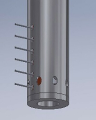
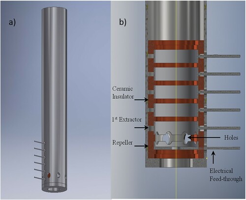
In our new compact design, the lens consists of six electrodes arranged as shown in . The electrodes are open tubes where the last one (at the entrance to the time-of-flight region) is a grounded electrode, all with inner diameter of 15 mm and an outer diameter of about 16 mm. The first (Repeller) electrode is closed off at one end with a metal plate to shape the VMI lens field. For this proof-of-principles study, the tubes are separated from each other using ceramic rings.Footnote2 The spacing between the electrodes is 1.5 mm except for the spacing between Repeller and Extractor (second electrode), which was set at 3 mm. In the region between Repeller and first Extractor eight evenly spaced 3 mm diameter holes are located, to allow the gas sample and laser beams into the lens. Another 3 mm diameter hole is located at the bottom of the lens, also allowing an on-axis molecular beam to enter. Dark orange areas in (b) indicate the ceramic insulator rings. Furthermore, an extra (grounded) metal tube was placed outside the lens to achieve an extra shielding and minimise any interference from external fields. This tube has an outer diameter of 22 mm and a total length of 11 cm. The high voltage connections to the lenses pass through this outside shield.
Figure 1. (a) Compact tubular VMI lens showing the 22 mm diameter 11 cm long metal shield with high voltage connections. (b) Cross section of the compact lens design, sliced at a plane including the electrical feed-through.
It is possible to improve the quality of image slicing by choosing a larger number than 6 tubular electrodes [Citation4], but this comes at the expense of a compact and simple design. As we show later in this paper, the degree of slicing obtained with our present design with 6 electrodes when using a typical 80 ns wide high voltage pulse to gate the channel-plate detector is slightly less than that from the conventional annular ring lens design. The tubular lens design can be used to obtain well-crushed images, however, and this is favourable, for example, when using the direct extraction method to obtain angular momentum polarisation information [Citation18].
3. Test measurments
3.1. Photodissociation
3.1.1. Experimental setup
The apparatus consists of differentially pumped source and detection chambers evacuated by a scroll pump and two turbo-molecular pumps. The molecular beam pulses are produced by a Nijmegen Pulse Valve (NPV) [Citation19] operating with a backing pressure of 2 bar of pure oxygen. A Nd:YAG laser, with 10 Hz repetition rate is used to pump a pulsed dye laser, and the fundamental beam of the dye laser, which operates with Coumarin-2 dye, was frequency doubled through a BBO crystal tuned to 224.995 nm with an energy output of 0.6 mJ. The beam was focused into the chamber using a 20 cm focal length lens. The electrodes were connected to high voltage power supplies with the first electrode (Repeller) was set at 4510 V, the second electrode (first extractor) at 4360 V, the third and fourth at 1262 and 478 V respectively and the fifth and sixth electrodes were connected to the ground (0 V). For the photodissociation study presented next, we effectively used five of the six electrodes, for consistency with the 5 lens design used in the inelastic scattering study, also presented here. The SIMION 8.1 software [Citation20] was used to find the optimal electrical parameters of the experiment, taking in account the mechanical aspects of this setup. For comparison, the same experiment was performed with O+ detection and a conventional VMI lens. In this case, the Voltages were 3000 V for the Repeller, 2495 V for the Extractor and 0 V for the Ground plate. The generated ions were accelerated by the VMI lens and passed the Time of Flight (TOF) region, before striking the dual Microchannel Plates (MCPs) / phosphor screen imaging detector, which is monitored by a Charged Coupled Device (CCD) camera. The detector gain was switched on at the arrival time of the O+ ions.
3.1.2. Results
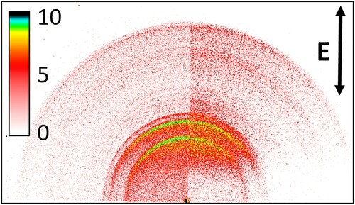
Raw O+ images formed by (2 + 1) REMPI at 224.995 nm via the 3dπ 3 (v=2) Rydberg state of O2, using a conventional 70 mm annular plate and a compact 16 mm diameter tubular VMI lens are compared side-by-side in . Due to the higher Repeller voltage used in the compact lens case, the images differ in size and are scaled to match at the largest ring radius. Multiple rings of O+ are visible, there are mainly formed by photodissociation of a large range O2+ vibrational states produced in the REMPI process [Citation2]. Identical ring patterns are visible in both cases, as depicted in .
Figure 2. Comparison of raw (log intensity scale) VMI images for O+ formation via 3dπ 3Σ (v=2) Rydberg state at 224.995 nm in vacuum. Left: Raw O+ image with the conventional lens. Right: Raw O+ image using the compact lens. Image intensity is represented by colour bar and the electric field of the linearly polarised REMPI laser is parallel to the detector face, in the direction indicated by the double headed arrow.
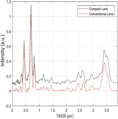
To further quantify the comparison an inversion of both images was carried out using a polar onion peeling inversion algorithm [Citation21,Citation22]. The resulting total kinetic energy release plots yield a similar pattern for the conventional and compact lens as shown in . Additionally, analysis using finite slice analysis (FinA) software [Citation23] indicates that both the conventional and compact tubular VMI lens designs have a rather typical slicing ratio of approximately 70–80%.
Figure 3. Total kinetic energy release distributions for O+ formation at 225 nm with an offset for clarity. The black and the red curve corresponds to compact and conventional lens, respectively.
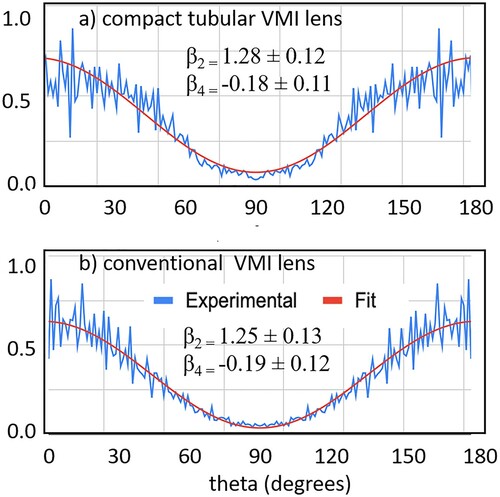
Another point of comparison is the angular distribution of the two images. shows the angular distributions of the main peak at 0.68 eV TKER for both cases. Generally, the angular distribution of the photodissociation products is described by the equation:
(1)
(1)
where θ is the angle between the outgoing fragment velocity and the polarisation vector, P2 and P4 are the 2nd and 4th order Legendre polynomials and
is the so-called anisotropy parameter
. The limiting values of
correspond to a pure perpendicular and a pure parallel transition respectively, where
indicated an isotropic distribution of ions. The anisotropy parameters
were calculated by fitting the experimental angular distribution to Equation (1). The red curves are the result of the best list square fit of Equation (1). As observed, the two angular distributions show a close resemblance, and the corresponding anisotropy parameters confirm this similarity.
Figure 4. Angular distribution of the 0.68 eV TKER peak in using (a) the compact tubular VMI lens, and (b) a conventional VMI lens.
3.2. Inelastic scattering
A compact lens design could be useful in many different experiments, particularly for detecting the scattering products of collision experiments. To test this, a rotationally inelastic scattering experiment of NO with Ar was performed using a slightly larger compact tubular VMI lens [Citation3] consisting of five tubular electrodes, with a total diameter (including shield tube) of 30 mm.
3.2.1. Experimental setup
A miniature crossed beam apparatus consisting of connected 12 cm cubes evacuated by 70 L/s turbo-molecular pumps, described in Ref. [Citation19], was used here. One-color resonant ionisation detection of nascent NO was driven by an excimer pumped dye laser system. The dye laser operated with Coumarin 47 dye and the fundamental beam was frequency doubled by a BBO crystal and fixed at ∼226 nm , with a pulse energy of 0.45 mJ/pulse. Two pulsed (NPV) molecular beams crossed at 90 degrees in the centre of the VMI lens. The primary valve was filled with 1% NO/Ar, and a backing pressure of 1 bar. The secondary valve contained pure Argon and was operating with a backing pressure of 6 bars. The voltages used to power the electrodes were 1085 V for the first electrode (Repeller), 1029 V for the second electrode (first Extractor), 1000 V for the third electrode, 500 and 0 V for the fourth and fifth electrodes respectively. The pressure during the experiment was 1·10−5 mbar inside the source chamber and 4·10−7 mbar inside the scattering chamber. For comparison, images that were obtained for the same final states of NO (j = 4.5, 9.5 and 12.5) using a standard annular plate VMI lens under roughly similar scattering conditions are reproduced here.
3.2.2. Results
Raw NO+ images for rotationally inelastic scattering of a cold beam of NO in Ar carrier gas with a pure beam of Ar obtained using a compact tubular VMI lens of 30 mm diameter are shown in (a) for excitation of the NO (j=0.5, e/f) initial state to the NO final rotational states, j’=4.5f, 9.5f and 12.5e states at ∼ 530 cm−1 collision energy. The lab velocity vectors for the Ar and NO beams and the propagation direction of the 226 nm (1 + 1) REMPI detection laser beam are shown along with a colour bar for intensity calibration, using event counting and 10000 laser shots.
Figure 5. Raw NO-Ar scattering images at ∼ 530 cm-1 collision energy using (a) the tubular VMI lens. In panel (b) images reported by Eyles et al. [Citation24] using a conventional annular ring VMI lens and roughly similar experimental conditions are shown for comparison. The Figure was adopted from Ref [Citation24] with the permission of The Royal Society of Chemistry.
![Figure 5. Raw NO-Ar scattering images at ∼ 530 cm-1 collision energy using (a) the tubular VMI lens. In panel (b) images reported by Eyles et al. [Citation24] using a conventional annular ring VMI lens and roughly similar experimental conditions are shown for comparison. The Figure was adopted from Ref [Citation24] with the permission of The Royal Society of Chemistry.](/cms/asset/3a22659f-0a4c-40c2-9556-88d3d37936be/tmph_a_1910357_f0005_oc.jpg)
In (b) the same final state images reported by Eyles et al. [Citation24] are shown after rotation of the images to the same laboratory velocity directions as in (a). Because Ref. [Citation24] used 1 + 1’ REMPI detection and hexapole state selection of the NO j=0.5, f initial state, the angular distributions are only qualitatively similar. Comparison of the sets of images in Figures (a) and (b) shows that the compact tubular lens design image quality is quite acceptable. The extended tail along the laser propagation direction – most apparent in the 12.5e image in (a) – is due to ions formed in regions extending past the acceptable ion volume length of the tubular lens, leading to distortion. This problem does not occur when ion volume is limited to the intersection of crossed laser beams as with 1 + 1’ REMPI used in the images in (b), from Ref. [Citation24]. These scattering results, and the photodissociation imaging results from the previous section, suggest that our very compact tubular VMI design can be employed in a wide range of molecular dynamics imaging experiments.
4. Summary
The aim of this work was to build a simple and very compact VMI lens suitable for photodissociation as well as for crossed beam scattering experiments. A VMI lens with 6 tubular electrodes of 16 mm diameter was constructed and its performance compared to that of a standard 70 mm diameter annular-plate VMI lens for photodissociation of O2 at 225 nm. Our results showed that the efficiency and radial and angular distribution quality of images from the compact lens is quite comparable to those of the traditional setup. A rough comparison of results from the two types of VMI lenses for NO-Ar scattering also showed the much smaller tubular lens yields good-quality images. Improvement of the image quality could be achieved by using slicing method by pulsing the MCPs with a narrower time window, as well as by using more tubular electrodes, as shown in Ref. [Citation4].
The compact tubular lens incorporated in a miniature imaging apparatus delivers high quality images at considerably less expense than conventional VMI setups, as long as the following requirements are met: (a) the molecular beam(s) are formed by pulsed valves (such as in Ref [Citation19]) with sufficiently short pulse-lengths and gas loads to ensure proper evacuation by small turbo-pumps, (b) the molecular beams are well-collimated, preferably to give a crossing volume comparable to the ionisation volume, and (c) (1 + 1’) ionisation with crossed laser beams is used, ensuring low ion recoil and a limited (1–10 mm3) ionisation volume. While the first conditions are easily met in modern imaging experiments, condition (c) remains as the greatest challenge for all imaging experiments, i.e. the availability of efficient low-recoil resonant ionizations schemes.
Acknowledgments
The authors acknowledge financial support from the EU H2020 ITN-EID project ‘PUFF’ (grant number 642820), and thank Prof. S. Cohen and Dr. S. Danakas (University of Ioannina, Greece) for distributing their inversion code. We are grateful to M. Balster for technical support and construction of the VMI apparatus, and Dr. Z.F. Sun for his support during the experiment. We would also like to acknowledge Dr. P. Kalaitzis and Dr. A. Khodabakhsh for their helpful advice and discussions.
Disclosure statement
No potential conflict of interest was reported by the author(s).
Additional information
Funding
Notes
1 A rule of thumb for optimal electrostatic lens design is to use less than 10% of the open aperture.
2 with extended use these ceramic rings will eventually charge up, distorting the image. In an actual design the lenses should be supported on an insulated post mounted outside the shield cylinder, in a free region determined by the application.
References
- D.W. Chandler and P.L. Houston, J. Chem. Phys. 87, 1445 (1987). doi:https://doi.org/10.1063/1.453276.
- A.T.J.B. Eppink and D.H. Parker, Rev. Sci. Instrum. 68, 3477 (1997). doi:https://doi.org/10.1063/1.1148310.
- B. van Oorschot, Master thesis, Radboud University Nijmegen, 2012.
- V. Plomp, Z. Gao and S.Y.T. van de Meerakker, Mol. Phys. 119, e1814437 (2020).
- E. Wrede, S. Laubach, S. Schulenburg, A. Brown, E.R. Wouters, A.J. Orr-Ewing and M.N.R. Ashfold, J. Chem.Phys. 114, 2629 (2001). doi:https://doi.org/10.1063/1.1337049.
- C.R. Gebhardt, T.P. Rakitzis, P.C. Samartzis, V. Ladopoulos and T.N. Kitsopoulos, Rev. Sci. Instrum. 72, 3848 (2001). doi:https://doi.org/10.1063/1.1403010.
- Y. Zhang, C.-H. Yang, S.-M. Wu, A. van Roij, W.J. van der Zande, D.H. Parker and X. Yang, Rev. Sci. Instrum. 82, 013301 (2011). doi:https://doi.org/10.1063/1.3505491.
- D.A. Chestakov, S.-M. Wu, G. Wu, D.H. Parker, A.T.J.B. Eppink and T.N. Kitsopoulos, J. Phys. Chem. A. 108, 8100 (2004). doi:https://doi.org/10.1021/jp0491111.
- V. Papadakis and T.N. Kitsopoulos, Rev. Sci. Instrum. 77, 083101 (2006). doi:https://doi.org/10.1063/1.2222084.
- N.G. Kling, D. Paul, A. Gura, G. Laurent, S. De, H. Li, Z. Wang, B. Ahn, C.H. Kim, T.K. Kim, I.V. Litvinyuk, C.L. Cocke, I. Ben-Itzhak, D. Kim and M.F. Kling, J. Instrum. 9, P05005 (2014). doi:https://doi.org/10.1088/1748-0221/9/05/P05005.
- S. Skruszewicz, J. Passig, A. Przystawik, N.X. Truong, M. Köther, J. Tiggesbäumker and K.-H. Meiwes-Broer, Int. J. Mass Spectrom. 365–366, 338 (2014). doi:https://doi.org/10.1016/j.ijms.2014.02.009.
- P. Jansen, D.W. Chandler and K.E. Strecker, Rev. Sci. Instrum. 80, 083105 (2009). doi:https://doi.org/10.1063/1.3206367.
- O. Tkáč, Q. Ma, M. Stei, A.J. Orr-Ewing and P.J. Dagdigian, J. Chem. Phys. 142, 014306 (2015). doi:https://doi.org/10.1063/1.4904901.
- T.R. Sharples, T.F.M. Luxford, D. Townsend, K.G. McKendrick and M.L. Costen, J. Chem. Phys. 143 (20), 204301 (2015). doi:https://doi.org/10.1063/1.4935962.
- W. Qi, P. Jiang, D. Lin, X. Chi, M. Cheng, Y. Du and Q. Zhu, Rev. Sci. Instrum. 89 (1), 013101 (2018). doi:https://doi.org/10.1063/1.5006982.
- P. Jiang, X. Chi, W. Qi, Q. Zhu and M. Cheng, Phys. Chem. Chem. Phys. 21, 14376 (2019). doi:https://doi.org/10.1039/C8CP07620K.
- P. Jiang, X. Chi, Q. Zhu, M. Cheng and H. Gao, Nat. Commun. 10, 3175 (2019). doi:https://doi.org/10.1038/s41467-019-11086-z.
- A.G. Suits, C.K. Bishwakarma, L. Song, G.C. Groenenboom, A. van der Avoird and D.H. Parker, J. Phys. Chem. A. 119, 5925 (2015). doi:https://doi.org/10.1021/jp509381q.
- B. Yan, P. Claus, B. van Oorschot, L. Gerritsen, A.T.J.B. Eppink, S.Y.T. van de Meerakker and D.H. Parker, Rev. Sci. Instrum. 84 (2), 023102 (2013). doi:https://doi.org/10.1063/1.4790176.
- D. Manura and D. Dahl, SIMION 8.1 User Manual [Scientific Instrument Services, Inc.] (2008), URL http://simion.com/manual/.
- G.M. Roberts, J.L. Nixon, J. Lecointre, E. Wrede and J.R.R. Verlet, Rev. Sci. Instrum. 80 (5), 053104 (2009). doi:https://doi.org/10.1063/1.3126527.
- K. Zhao, T. Colvin, W.T. Hill and G. Zhang, Rev. Sci. Instrum. 73, 3044 (2002). doi:https://doi.org/10.1063/1.1493231.
- J.O.F. Thompson, C. Amarasinghe, C.D. Foley, N. Rombes, Z. Gao, S.N. Vogels, S.Y.T. van de Meerakker and A.G. Suits, J. Chem. Phys. 147, 074201 (2017). doi:https://doi.org/10.1063/1.4986966.
- C.J. Eyles, M. Brouard, H. Chadwick, B. Hornung, B. Nichols, C.H. Yang, J. Kłos, F.J. Aoiz, A. Gijsbertsen, A.E. Wiskerke and S. Stolte, Phys. Chem. Chem. Phys. 14, 5403 (2012). doi:https://doi.org/10.1039/c2cp23258h.