
 ?Mathematical formulae have been encoded as MathML and are displayed in this HTML version using MathJax in order to improve their display. Uncheck the box to turn MathJax off. This feature requires Javascript. Click on a formula to zoom.
Abstract
Recent developments in high-magnetic-field fusion systems have created large incentives to develop flibe (Li2BeF4) salt fusion blankets that have four functions: (1) convert the high energy of fusion neutrons into heat for the power system, (2) convert lithium into tritium—the fusion fuel, (3) shield the magnets against radiation, and (4) cool the first wall that separates the plasma from the salt blanket. Flibe is the same coolant proposed for fluoride-salt-cooled high-temperature reactors that use clean flibe coolant and graphite-matrix coated-particle fuel. Flibe is also the coolant proposed for some molten salt reactors (MSRs) where the fuel is dissolved in the coolant. The multiple applications for flibe as a coolant create large incentives for cooperative fusion-fission programs for development of the underlying science, design tools, technology (pumps, instrumentation, salt purification, materials, tritium removal, etc.), and supply chains. Other high-temperature molten salts are being developed for alternative MSR systems and for advanced Gen-III concentrated solar power (CSP) systems. The overlapping characteristics of flibe salt with these other salt systems create significant incentives for cooperative fusion-fission-solar programs in multiple areas.
We describe the fission and fusion flibe-cooled systems, what has created this synergism, what is different and the same between fission and fusion in terms of using flibe, and the common challenges. We review (1) the characteristics of flibe salts, (2) the status of the technology, (3) the options for tritium capture and control in the salt, heat exchangers, and secondary heat transfer loops, and (4) the coupling to power cycles with heat storage. The technology overlap between flibe systems and other high-temperature MSR and CSP salt systems is described. This defines where there are opportunities for cooperative programs across fission, fusion, and CSP salt programs.
I. INTRODUCTION
This paper describes the fission and fusion applications for flibe salt with overlapping areas of science, technology, challenges, and future directions. shows the proposed affordable, robust, and compact (ARC) fusion system,Citation1,Citation2 the flibe fusion blanket, and the proposed fluoride-salt-cooled high-temperature reactor (FHR). The startup company Commonwealth Fusion Systems (CFS) is developing the ARC fusion concept in cooperation with the Massachusetts Institute of Technology (MIT) Plasma Science and Fusion Center. Eni S.p.A (ENI)Footnotea is working with MIT to address many of the longer-term challenges associated with this fusion system. The startup company Kairos Power is developing the FHR. Significant efforts on the FHR are underway at MIT, the University of California at Berkeley, the University of Wisconsin at Madison, the Georgia Institute of Technology, Oak Ridge National Laboratory, and many other institutions. In China, the Shanghai Institute of Applied Physics (SINAP) is building a 2-MW(thermal) molten salt reactor (MSR). There are smaller efforts to develop these technologies in Europe and elsewhere. Major experimental facilities using flibe salt are under design in the United States and China.
Fig. 1. (a) ARC fusion system, (b) flibe fusion blanket for ARC, and (c) FHR fission system
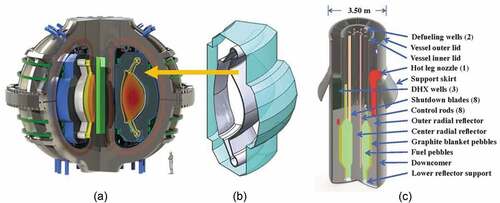
Work on flibe blankets for various magnetic and inertial fusion systems goes back to the 1960s (CitationRefs. 3–9 through Citation10) but there has been little work in the fusion community for the last 15 years. Advances in technology (discussed below) indicate many future machines will use flibe blankets. Work on flibe for reactor systems goes back to the 1950s and the early development of MSRs. Most of the recent work on flibe has been done for the FHR (United States) and MSR (China) within the last decade.
There are other developments that impact technology developments for flibe salt systems. There is significant work with multiple startup companies and other organizations to develop MSRs with other fluoride salts that have physical properties similar to flibe. The European CommunityCitation11,Citation12 has a project to develop a fast-spectrum MSR using a lithium heavy-metal fluoride salt with many of the same tritium challenges associated with flibe salt. The proposed next-generation concentrated solar power (CSP) systems use a sodium-potassium-magnesium-chloride salt as the heat transfer and heat storage salt.Citation13 This salt has a melting point near 400°C, an expected peak operating temperature of ~750°C, and operates under chemically reducing conditions to minimize corrosion. The temperature range and chemically reducing operating conditions are similar to flibe salt resulting in technology overlap in the development of pumps, valves, instrumentation, power cycles, and other areas of salt technology. Last, there is ongoing work to develop molten chloride fast reactors (MCFRs) with fuel dissolved in the salt that operate at similar temperatures.
Most of these developments have occurred in the last 5 years; thus, only recently at MIT and elsewhere have research and development efforts begun to be integrated across different salt power system technologies. This paper has the goal to provide an integrated perspective on flibe technology and its coupling to other work on high-temperature salt systems to accelerate cooperative development and commercialization of these technologies
II. ARC FUSION POWER PLANT
Recent advances in manufacturing have enabled the large-scale production of rare-earth barium copper oxide (REBCO) superconducting tape. This, in turn, has enabled the building of large magnets with double the magnetic field of previous large superconducting magnets. In magnetic fusion systems the system size scales as one over the fourth power of the magnetic field. Doubling the magnetic field can reduce the size of the fusion machine by an order of magnitude for the same power output resulting in a fusion machine where the power density increases by an order of magnitude with large reductions in cost per unit of power output. This is the basis for the ARC fusion concept.Citation1,Citation2 It is a one-time improvement. With REBCO magnets, the maximum magnetic fields that can be generated are limited by the strength of the materials holding the magnets together—not by the ability to generate magnetic fields. shows the conceptual design of the ARC. The ARC is the first fusion machine that proposes to use these new magnetic materials, but the expectation is that most future magnetic fusion systems will use REBCO or some future equivalent magnet material to reduce system size and cost.
The ARC requires a fusion blanket that (1) converts energy from fusion neutrons into heat for the power system, (2) converts lithium into tritium as fast as the tritium is consumed, (3) shields the magnets against radiation, and (4) cools the first wall/vacuum vessel (VV) that contains the plasma. Many different designs of fusion blankets have been proposed with different coolants.Citation14 High-magnetic-field fusion relative to other magnetic fusion machines changes the blanket design requirements in two ways. First, the power densities increase by an order of magnitude. The much higher power densities make it difficult to cool solid blankets that provide shielding and breed tritium. Second, the higher magnetic fields create large incentives to use a coolant in the blanket that has low electrical conductivity relative specifically to lithium-lead-cooled systems to reduce interactions between the flowing coolant and the magnetic fields. These considerations lead to the use of a liquid salt flibe blanket.
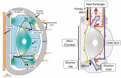
The ARC is a tokamak where the machine is a torus (). shows the cross section. There are massive heat loads from the fusion process on the first wall; thus, most of the cold flibe salt from the heat exchanger flows through multiple channels to provide first-wall cooling before entering the large flibe blanket and returning to the main heat exchanger. The nominal design characteristics of the ARC and the flibe blanket are summarized in .
TABLE I Nominal ARC Blanket Design Parameters
Fig. 2. ARC machine and flibe blanket
Flibe is proposed because it is the best liquid salt for breeding sufficient tritium fuel for a self-sufficient fusion machine.Citation15 The beryllium in the salt multiplies the number of neutrons via a (n, 2n) reaction, and neutron adsorption by lithium produces tritium. Isotopically enriched lithium with 90% 6Li is used to maximize tritium production. The breeding ratio is estimated at 1.1; that is, for every tritium atom consumed in the fusion reaction, 1.1 tritium atoms are created. A minimum breeding ratio of 1 is required for the fusion reactor to be self-sustaining in tritium production assuming no tritium losses in the system or radioactive decay of tritium.
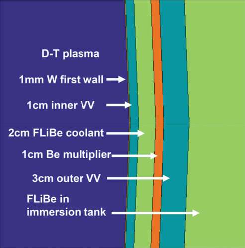
The proposed first-wall structure is a double-wall () structure with a sacrificial layer facing the plasma backed by Inconel-718 as the structural material, a flibe cooling channel, a second wall with beryllium backed by Inconel, and the main flibe tank. Flibe from the wall-cooling channel empties into the main tank. About 25% of the heat from the system is deposited within this structure. This includes heat from (1) the plasma on the plasma-facing wall, (2) neutron heating from slowing down of neutrons by the beryllium, flibe, and Inconel, and (3) various other nuclear reactions. The beryllium metal layer acts as a neutron multiplier via a high-energy neutron yielding two neutrons. Part of the blanket structure includes a diverter that acts as a drain to remove high-energy plasma from the system that contains deuterium, tritium, and the helium reaction product. This localized area sees much higher heating loads from the plasma but lower neutron fluxes. It contains additional special features to withstand the higher localized heat loads. Alternative first-wall designs are being evaluated with the common features of a channel with high-velocity flibe flow to provide sufficient first-wall cooling and a solid layer of beryllium or some other material for neutron multiplication.
Fig. 3. ARC double-wall VV structure
While the main nuclear reactions are the beryllium neutron multiplication reaction and the lithium tritium production, there are many secondary nuclear reactions () creating short-lived radionuclides. This generates a significant gamma radiation field from the flibe salt flowing outside the reactor and a small amount of decay heat for several weeks after shutdown. There will also be activated corrosion products from materials in contact with flibe. There is no radiation damage to liquid flibe salt; however, if flibe salt is allowed to freeze, at very low temperatures irradiating solid flibe salt or other fluoride salts will generate free fluorine—a corrosive gas. Upon freezing there is only a 2% change in volume.
Fig. 4. Nuclear reactions with flibe salt.Citation8
The development pathway for the ARC has three major steps. The first step is to develop and demonstrate the REBCO superconducting magnets at scale with the high magnetic fields that create high stresses within the magnet. Smaller, simpler magnets have been built with REBCO. The CFS goal is to do this within 3 years. The second step would be a fusion machine called SPARC (CitationRefs. 16 and Citation17) to demonstrate net energy production (more fusion energy out than energy into the plasma) and the associated reactor physics. This machine would operate for short periods of time with the neutron energy dumped into solid neutron shields and adsorbed by the structure by raising its temperature. It would be designed to operate for 1000 to 2000 cycles. The ARC would be a commercial demonstration project producing power with self-sufficient tritium generation. It requires a flibe blanket for heat removal and tritium generation.
III. FHRs ANcit000D LIQUID-FUELED MSRs
The FHR is a new reactor concept,Citation18–20 less than 20 years old, that combines a clean fluoride salt coolant (no dissolved fuel or fission products), the graphite-matrix coated-particle fuel originally developed for high-temperature gas-cooled reactors (HTGRs), and passive decay heat removal systems from sodium fast reactors (SFRs). The baseline FHR uses pebble-bed fuel and 7Li2BeF4 (flibe) salt coolant enriched in 7Li to minimize tritium production. Fluoride salt coolants are used because they are chemically compatible with the carbon-based fuel and fluorine has a small neutron adsorption cross section. Flibe is the best salt coolant in terms of thermal hydraulics and neutronics performance.Citation21,Citation22 A schematic of the pebble-bed FHR is shown in .
Fluoride-salt-cooled high-temperature reactors are a family of reactor concepts characterized by the use of a high-temperature fuel and a fluoride salt coolant where there is an equivalent FHR concept for each major variant of an HTGR. A liquid salt replaces the gas coolant of the HTGR resulting in a reactor that operates at near atmospheric pressure with power densities 4 to 10 times higher than the equivalent gas-cooled reactor because liquids are better coolants than gases. Flibe and other salt coolants are mixtures of fluoride salts to lower melting points. Chloride salts are not viable for thermal-spectrum reactors because of their high neutron cross sections. The pebble-bed FHR is the most advanced designCitation20 with a nominal design shown in and design parameters in . The Kairos Power FHR is a variant of this design.
TABLE II Design Parameters of a Pebble-Bed FHR
There are several incentives for developing the FHR. Revenue per unit of thermal heat output is increased because the average temperature of delivered heat to the power cycle is ~650°C, higher than the average temperature of delivered heat from helium-, sodium-, and water-cooled reactors (). Flibe has a melting point of 459°C resulting in minimum salt temperatures near 550°C to minimize the risk of freezing and peak salt temperatures near 700°C because of limits of materials for practical heat exchangers. Higher temperatures enable (1) higher heat-to-electricity efficiency, (2) higher temperature delivered heat to industry, and (3) more efficient coupling to heat storage technologies that enables variable electricity to the grid from a base-load reactor to enhance revenue (Sec. VI). This advantage applies to all fission, fusion, and Gen-III CSP salt systems because all of the salts have high melting points. The safety case is based on several factors. The FHR is a low-pressure reactor with HTGR fuel that has a high heat capacity. The high heat capacity results in slow heat up of the reactor core under any accident conditions. Safety is aided by the very high-temperature capabilities of the HTGR fuel where fuel failure temperatures are above 1650°C, the salt coolant has a boiling point above 1400°C, and a coolant that dissolves most fission products if there are fuel failures.
TABLE III Heat Delivery Temperatures for Different Reactor Coolants
There are also significant ongoing efforts to develop MSRs where the fuel is dissolved in a fluoride salt. Different designs use different fluoride salts.Citation23 The SINAP (CitationRef. 24) is in the process of designing and building a 2-MW graphite-moderated MSR using flibe salt. In the United States the startup company FLiBe Energy Inc. is also proposing to use flibe salt. The graphite moderator in the reactor core has holes for the flowing fuel salt. The dissolved fissile, fertile, and fission products change some of the properties of the flibe salt including radiative heat transfer. Countries in Europe have been working on a fluoride salt fast reactorCitation11,Citation12 that uses a lithium heavy-metal fluoride salt. This reactor has no graphite in the core. Like the FHR, all of the MSRs with lithium-containing salts use 7Li to minimize tritium generation. Tritium is generated and thus systems to control tritium releases to the environment are required that are similar to the FHR.
There is also an effort to develop fast-spectrum MSRs by TerraPower where the fissile, fertile, and fission products are dissolved in a chloride saltCitation25 containing isotopically separated 37Cl. In a fast-spectrum MSR, the fuel salt flows through a 1-m-wide vessel with no internal components while generating heat internally within the salt from fission. The thermal hydraulics of high power generation in flowing salt through a wide channel has similarities to the ARC fusion blanket. The operating temperatures of these chloride salts are similar to the FHR.
IV. DIFFERENCES BETWEEN FISSION AND FUSION FLIBE USE
Fission and fusion use of flibe results in many common challenges, but there are some important differences driven by different constraints and requirements.Citation26
IV.A. Power Cycles and Heat Storage
Many FHR and MSR designs include high-temperature heat storage to enable economic base-load operation with variable electricity to the grid to match changing market requirements and maximize revenue,Citation27 as discussed in Sec. VI. This change in future plant designs has major implications for the ARC and many other fusion systems. Most fusion systems operate in a pulse mode. For inertial fusion the pulses may be seconds whereas for magnetic fusion the pulses may be many hours followed by a short period of time before back to full power. The addition of heat storage decouples short-term fusion heat output from the requirement to deliver electricity to the grid or heat to industry. It reduces power plant constraints on fusion system design; consequently, the incentives for heat storage are greater for fusion machines.
IV.B. Thermal Hydraulics
Flibe is a eutectic mixture of two salts (LiF and BeF2) to lower its melting point. Like other fluoride salts, flibe has a high Prandtl number (low thermal conductivity) relative to other coolants. However, there are some important differences in the use of flibe in fission versus fusion systems:
Magnetic fields: Fusion systems have very high magnetic fields that interact with flowing flibe to change the thermal hydraulics via mechanisms such as suppression of turbulence.Citation28,Citation29 These heat transfer effects are not fully understood for flibe.
Radiative heat transfer: Flibe is semitransparent and at 700°C radiative heat transfer begins to become important.Citation30 Radiative heat transfer reduces temperature differences in the system. This is significant in an FHR, particularly in accident scenarios. However, it is more important in the fusion system where the peak heat generation in the liquid blanket is next to the inner wall of a 1-m-thick blanket. In such a system longer-distance transport of radiative heat can become important.
Geometric effects: In the FHR there is good mixing of the coolant flowing through a pebble bed. In a flibe fusion blanket tank () one concern is uneven flow and formation of vortexes where flibe remains relatively stationary in some locations. Because of the high internal power generation in flibe, if vortexes form it could result in locally rapid heating of flibe to the boiling point and large variations in flibe salt temperatures at the outlet of the blanket. This has similarities to the challenge in fast-spectrum MSRs where the fuel salt is flowing through a channel more than 1 m in diameter with very high rates of heat generation in the salt.
Extreme heat fluxes: The first wall of the fusion machine that separates the plasma from the salt has high heat fluxes (0.17 MW/m2) with much higher local heat fluxes in the diverter. These heat fluxes are much higher than found in an FHR. In addition, there is high internal heating of the first wall from the gamma and neutron fluxes. At the same time the peak temperature limits for the fusion first wall are below the temperature limits for graphite-matrix FHR fuel.
There are good low-temperature simulants for flibe that can be used for many heat transfer testsCitation31 such as Dowtherm A; however, these materials can’t simulate radiative heat transfer or impacts of magnetic fields on heat transfer. Computational fluid dynamics is required to design the fusion blanket. Separate effects experiments are required to understand the individual phenomena that are then combined using computational fluid dynamics. A small number of expensive highly integrated experiments may be required to validate design codes. Much of this work would also be useful for the FHR and MSR.
IV.C. Tritium
The ARC and FHR have tritium challenges. Tritium production in the FHR with isotopically separated 7Li is about two orders of magnitude higher than releases from a pressurized water reactor (PWR), but three orders of magnitude less than the production rate in a fusion machine. In a PWR the tritium is primarily from the lithium and boron in the water coolant. In the FHR the lithium is 99.99+% 7Li to minimize tritium production. For the ARC fusion machine, the nominal lithium isotopic composition is 90% 6Li to maximize tritium production. Both systems require efficient tritium removal from salt and control of releases to the environment. In addition to the higher tritium levels in a fusion machine, there are two important differences with regard to tritium management requirements in fusion versus fission machines:
Tritium waste or fuel: In an FHR the tritium is a waste or a secondary product whereas fusion machines require efficient recycling for the fusion reactor to be self-sufficient in tritium. Tritium has some value today, particularly its decay product 3He. As a consequence, for an FHR there is an incentive to recover the tritium for the market, but no requirement for efficient recovery. Certain tritium removal options such as gas sparging may sparge with a hydrogen/inert gas mixture to (1) remove tritium and (2) control salt redox (corrosion) potential. Extra hydrogen mixed with the tritium is not a concern for an FHR. In a fusion machine any normal hydrogen has to be removed before the tritium is recycled to the plasma.
Safety basis: In a fusion machine, the primary accident source term is the tritium. There are large incentives to minimize the tritium inventory to minimize the accident source term and required safety systems. This creates incentives for fast recovery and recycling of tritium from the flibe blanket.
There has been significant recent work on tritium controlCitation19,Citation32 for the FHR, including irradiation of different materials in flibe salt at 700°C. There has been much less recent work on tritium control for fusion for flibe systems. In each case, neutrons interact with LiF to generate tritium in the form of 3HF and helium. Hydrogen fluoride is highly corrosive so a chemical redox agentCitation33 is added to the salt to convert the 3HF to 3H2. Section V discusses the common technologies for tritium control.
V. FLIBE SYSTEMS
The status and challenges with flibe systems are discussed herein recognizing that major flibe test facilities are expected to come online in the next 5 years in the United States (FHR, ARC) and in China (MSR).
V.A. Supply Chain
The supply chain challenges to produce flibe are identical for both systems. The FHR will use isotopically separated 7Li while the ARC uses lithium isotopically enriched in 6Li. Lithium isotopic separation facilities are required. The United States (University of Wisconsin at Madison, Oak Ridge National Laboratory) and China can today produce small quantities of purified flibe at laboratory scale (tens of kilograms per batch) not industrial scale (tonnes). Industrial-scale flibe supply chains are being developed by Kairos Power for the FHR in the United States and the SINAP in China for salt reactors. This includes capabilities to isotopically separate lithium isotopes.
V.B. Properties
Flibe systems and tritium management options follow directly from the physical characteristics of flibe. The properties of flibe and several other fluoride salts are shown in . FlibeCitation34,Citation35 is the primary liquid-salt option for fusion to obtain the high tritium breeding ratio that is required. The other salts could be potentially used in some types of FHRs and MSRs. Flibe has better neutronic and thermal-hydraulic propertiesCitation19,Citation21,Citation22,Citation36 than the other salts. For FHRs, the disadvantages of flibe versus other salts are the toxicity of beryllium and the cost of isotopically separated lithium.
TABLE IV Candidate Reactor Coolant*
Recent critical reviewsCitation21,Citation22 have evaluated the physical properties of flibe and the uncertainties associated with those physical properties. There are significant uncertainties associated with the thermal conductivity, partly because flibe is semitransparent and at higher temperatures radiative heat transport becomes a significant heat transport mechanism. The major area of missing physical property data is measurement of radiative heat transfer and other optical properties as a function of temperature, frequency, and impurity levels. This is important for multiple reasons:
Heat transfer: Above 700°C radiative heat transfer becomes important and becomes a significant factor in minimizing peak coolant temperatures. This is relevant in the context of accident conditions for FHRs and MSRs. It is also relevant to reducing peak temperatures in the ARC. In a large flibe blanket tank or flow channel, radiative heat transfer can change temperature distributions and thus flows.
Instrumentation: The optical properties create new instrumentation options that may be required for fusion and useful for fission. Infrared imaging can detect hot spots associated with the first wall through the flibe. Second, Cherenkov imaging diagnostics from neutron interactions with the flibe salt may enable direct measurement of fusion power.
The salt melting points for fission, fusion, and Gen-III solar systems are high relative to other coolants such as water, helium, and sodium. Special engineering features are required to avoid salt freezing. The compensating feature is the very high boiling points so that in most circumstances there is little risk of boiling.
V.C. Corrosion
Liquid flibe salt is chemically stable in high neutron and gamma radiation fields. It is an ionic solution. Frozen flibe salt near room temperature in high radiation fields will generate free fluorine. Lithium fluoride plus a neutron yields tritium fluoride (3HF) and helium. Tritium fluoride is highly corrosive. To prevent corrosion, a chemical reducing agent is required. The leading candidate is beryllium metal that is slightly soluble in flibe and rapidly reacts with HF (CitationRef. 37). Beryllium plus two tritium fluorides yields BeF2 plus 3H2—hydrogen. In flibe salt, hydrogen remains as diatomic hydrogen. Other reducing agents can be used to convert 3HF to 3H2. The reference ARC design has beryllium exposed to flibe. If dissolution rates of beryllium are too high or localized, a more powerful reducing agent may be required to minimize beryllium dissolution into the salt.
Fluoride salts are fluxing agents; that is, they dissolve oxide and other coatings. The only way to prevent corrosion of the metal is to have the chemical redox conditions in the salt more reducing than the metals of construction; that is, the metals must be noble relative to the salt.Citation33 shows the chemical redox potential of various elements. The materials of construction determine the redox conditions required to minimize corrosion. With the requirements for redox control is the associated requirement to develop robust methods to measure and control the redox potential to assure corrosion control. Multiple methods to measure redox control have been developed in a laboratory setting but what is required is development of a redox control strategy and instrumentation with the reliability requirements for power plant operations. In this context, there is a large difference between MSRs and clean flibe systems. In a fluoride salt MSR the historical strategy to control redox is to control the ratio of dissolved +3U/+4U in the salt. With the high concentrations of uranium in the salt, measurement and thus control of redox potential is straightforward.
Fig. 5. Redox potentials of various redox couples as function of temperature in fluoride salts. Solid line: metal dissolution at of 10−6; dotted line: reduction of oxidants. HF/H2 represents the mole ratio of HF/H2 at 1 atm total pressure
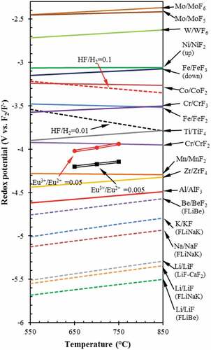
Material choices are first limited by the requirements to be compatible with flibe salt as shown in . Note that the HF/H2 = 0.01 potential is above the Cr/CrF2 potential implying that HF will react with chromium metal to produce chromium fluoride and H2. Chromium is an alloying agent in almost all high-temperature materials. Structural material choices depend on if one wants a code-qualified material. Using code-qualified materials simplifies licensing, and code-qualified materials are commercially available. However, it requires nearly a decade to fully qualify a structure material. There is the option of adding nonstructural materials including tungsten and nickel as coatings for corrosion control. Adding carbon to the system, such as the fuel in the FHR, can increase corrosion rates during irradiation.Citation19,Citation36 All materials in contact with electrically conductive flibe must be considered because of the potential of galvanic corrosion between different materials of construction, In some designs of FHRs this has led to the decision to use a single material of construction, 316 stainless steel, to avoid such interactions. Material decisions are at an earlier stage of development for fusion. This paper does not go further into this complex subject.
Coupled to materials and tritium control is purification of the flibe salt to minimize corrosion. Some impurities in all materials of construction will leach into the salt over time. Neutron irradiation will generate other species in the salt, such as oxygen, and by interactions with the materials of construction creating corrosion products that will dissolve in the salt. Fuel in FHRs and operations will add impurities. Like other coolants, the impurities in the salt coolant can have a large impact on corrosion rates. It is not known at this time what the online purification requirements will be.
The traditional method to purify flibe involves fluorination with HF that strips volatile fluoride impurities from the salt including oxygen as steam, controlling redox by the ratio of hydrogen to HF to precipitate most remaining impurities, then followed by filtering any metal particulates in the salt. This method is robust and works well as a production method for flibe salt. If producing flibe salt from beryllium and lithium fluorides, low-cost feedstocks may come with high levels of impurities and thus the need for such a process. For a fission or fusion reactor, the question is whether simpler processes can be developed for online or batch purification of salts with lower concentrations of impurities.
There are other purification options including distillation.Citation38 Distillation was experimentally investigated for flibe salt in the 1970s for online purification of MSR salts and looked potentially attractive. However, with the existing 1970s materials of construction, the only option was vacuum distillation, which is a low-throughput process with limited separation capabilities. Higher-temperature multistage distillation was not viable because of the limits in the fabrication of high-temperature materials such as molybdenum into complex shapes. New methods of additive manufacturing may enable building high-performance high-temperature distillation columns of molybdenum or other materials that would enable distillation as a high-capacity low-cost no-additive salt cleanup option. There are other options such as carbon beds that may be able to remove impurities other than tritium (Sec. V.D.1.c) but very little work has been done on such longer-term options. Much of the ongoing work in this area is associated with MSR salt cleanup and the conversion of wastes into acceptable waste forms.
V.D. Tritium Challenge
Tritium capture and control is a major challenge with flibe and other lithium-containing salts. Tritium is the fusion fuel with the requirements for (1) efficient recovery for a self-sustaining fusion reactor, (2) fast recovery to minimize total tritium inventory in the fusion plant (minimize inventory and thus accident source term), and (3) avoiding significant releases to the environment. In fission machines, the goal is to minimize releases to the environment with tritium generation rates typically three orders of magnitude lower than in a fusion machine. In addition to traditional MSRs with flibe, the European Community has been developing a fast-spectrum MSR with a 7Li heavy-metal fluoride saltCitation11,Citation12 where lithium is used to reduce the salt melting point. Tritium capture and removal can be done in the (1) salt, (2) certain types of heat exchangers, and (3) secondary heat transfer loops. All options are discussed herein. There is no consensus on preferred options for tritium control and none of the technologies have been demonstrated at significant scale in salt systems.
V.D.1. Removal of Tritium from Salt
There are many methods to remove tritium (3H) from the salt. Recent reviewsCitation32 summarize some of these options. To understand the performance limits of these systems, one must understand the behavior of hydrogen in flibe. shows hydrogen diffusivity in flibe and other materials that may be found in a flibe fission or fusion system. shows the solubility of hydrogen in flibe and other materials that may be found in a flibe system. For diatomic molecules such as hydrogen, the solubility follows Sievert’s law in metals including liquid sodium (discussed in Sec. V.D.3.c) where the solubility is proportional to the square root of the hydrogen pressure. In liquids such as salts, the solubility of diatomic hydrogen follows Henry’s law where the solubility is proportional to the pressure of the hydrogen. These two physical properties drive the choice of options to capture tritium or to prevent its escape from flibe.
Fig. 6. Hydrogen diffusivity in flibe, Flinak, sodium, and different metals. Values are extrapolated from available experimental range. Flibe and Flinak from 773 to 873K (CitationRef. 40), sodium from 742 to 853 K (CitationRef. 42), SS316 and Ni from 500 to 1200 K (CitationRef. 39), and tungsten from 1100 to –2400 K (CitationRef. 41)
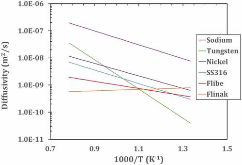
Fig. 7. Hydrogen solubility versus temperature for different materials. Values are extrapolated from available experimental range. Flibe and Flinak from 773 to 873 K (CitationRef. 40), sodium from 742 to 853 K (CitationRef. 42), SS316 and Ni from 500 to 1200 K (CitationRef. 39), and tungsten from 1100 to 2400 K (CitationRef. 41). The experimental values for the low estimate of graphite are based on high-density isotropic Isograph-88 extrapolated from 1123 to 1323 K, and the high estimate is estimated based on recent experiments on carbon materials at 973 K (CitationRefs. 43 and Citation44)
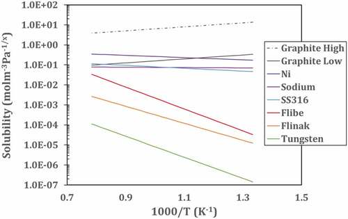
The permeation (transport) rate of hydrogen is proportional to the diffusivity times the solubility. In terms of permeation rates, diffusivity can be considered a measure of the difficulty of a molecule moving through a material, whereas the solubility is a measure of positions that can be occupied by tritium and therefore the number of pathways for a molecule to move through a material. Liquid salts have low diffusivity relative to most materials and low hydrogen solubility. Tritium (3H2) moves very slowly through flibe. As a result, the primary limit of any tritium removal from a flibe system is the time it takes the tritium molecules to diffuse from the bulk salt to some surface for removal of the tritium. This results in tritium removal options where in each case the surface area and fluid transport via turbulence often determines the rate of tritium removal.
shows a typical schematic of a system to remove tritium from the salt. The specific example is for tritium removal using permeation membranes. The tritium removal system is before the main heat exchanger in hot flibe salt to reduce the concentration of tritium in the salt entering the heat exchangers and thus the tritium concentration driving force for diffusion of tritium through the heat exchangers. Most of the external system surface area is associated with the heat exchangers. Some systems to remove tritium from salt will remove tritium and tritium fluoride (gas spargers, carbon beds, etc.), but in all cases are more efficient in removing tritium gas (3H2) than tritium fluoride because tritium gas diffuses faster through flibe salt to the surface of the tritium removal system. Permeation membranes and heat exchangers only remove tritium gas. Tritium removal systems thus change the ratio of tritium to tritium fluoride in the salt. The redox control agent is required to maintain the desired redox potential.
Fig. 8. Schematic of the tritium control and mitigation system
V.D.1.a. Gas Sparging
In gas spargingCitation32 an inert gas or a hydrogen/inert gas is bubbled through the salt to remove the tritium. Hydrogen in the sparging gas may be used for redox control. For the FHR, tritium with added hydrogen implies a somewhat larger waste stream with tritium. For fusion, the use of hydrogen or deuterium in the gas sparging system implies the need to later separate the tritium for recycling back to the fusion plasma. The tritium removal effectiveness depends upon the bubble surface area.
This technology is being developed by SINAP where gas is injected, goes through a structure to create turbulent mixing between the gas and liquid, and then through a centrifugal system that results in efficient separation of gas from the flibe salt. The SINAP development work is for FHRs and MSRs. In a MSR the system also removes xenon, which is a strong neutron poison, as well as other gaseous fission products and some noble metals. There are large economic incentives for the fast removal of xenon to minimize parasitic neutron losses in the reactor core. The many short-lived fission products result in an off-gas system with very high radiation levels, which creates incentives to minimize equipment size and thus radiation shielding. There are many other variants, such as a gas scrubber where the liquid flows downward over some packing forming a thin layer on the surface of the packing as the purge gas travels in the upward direction. In these systems there is a trade-off between equipment size, energy consumption, and volume of expensive flibe in the separation system.
V.D.1.b. Vacuum Disengager
In a vacuum disengagerCitation45 the hot flibe salt is sent to a vacuum tower where spray nozzles create small droplets (). Tritium diffuses out of the droplets as they fall and is removed by vacuum pumps. This option was examined in the 1990s as part of the U.S. inertial fusion program. In the initial design the optimum droplet size was 0.2 mm in a 7-m-tall vacuum tower. A two-stage system was estimated to provide a decontamination factor of 100 000 and thus meet requirements for tritium capture and allowable releases. The vacuum disengager is between the fusion chamber and the first heat exchanger to remove tritium before entering the heat exchanger. The major trade-off is between the size of the droplets and vacuum pressure losses. Smaller droplets result in higher diffusion rates of tritium from the center of the droplet to the surface, but higher concentrations of droplets result in the buildup of tritium gas backpressure from the droplet surfaces to the vacuum pumps. No experimental work was done. We are not aware of any recent work in this area.
Fig. 9. Tritium gas diffusion out of flibe spay region. (Droplet size is exaggerated.)
V.D.1.c. Solid Adsorbers
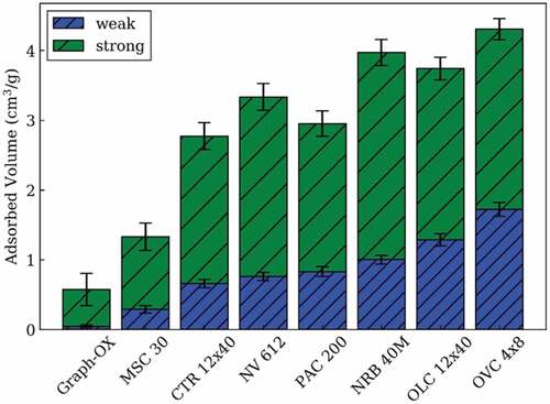
A particle bed of a solid adsorber can be used to remove tritium from the flibe. Such beds can have very high surface areas. The tritium is desorbed from the bed by heating. The leading candidate is a carbon bed because carbon is compatible with fluoride salts and has high solubility to hydrogen. The primary choices are carbon and the materials that are noble (chemically inert) to flibe (). There is almost a two order of magnitude difference in the solubility of hydrogen on different forms of graphite (). Recent experimental workCitation46 at MIT has measured hydrogen solubility at 700°C for a variety of carbon forms as shown in . Carbon has several different types of sites that adsorb hydrogen where the concentrations of each type of site depend on how the graphite was processed. Most hydrogen is weakly or strongly adsorbed. The quantity of weakly adsorbed hydrogen depends upon the hydrogen (or tritium) pressure. If the goal is a hydrogen bed to remove tritium from flibe, one wants a carbon in a form with a high solubility for weakly adsorbed hydrogen to enable easy recovery of the hydrogen. However, this also implies that in a reactor core that has a carbon form with a high solubility for hydrogen that is weakly adsorbed, hydrogen (or tritium) will be quickly released in an over-temperature event.
Fig. 10. Quantities (standard temperature and pressure in cubic centimeters/grams) of weak and strong adsorption at 3 kPa
In the pebble-bed FHR, the fuel and graphite moderator pebbles spend an average of a month traveling through the reactor core. They are then inspected, with the fuel pebbles that have reached their burnup limits sent to spent nuclear fuel storage and the remainder of the pebbles recycled back to the core. The specific characteristics of this reactor core design may allow the fuel and graphite pebbles in the core to be used as a tritium removal system by heating the pebbles after exiting the core to remove the weakly bound tritium. There is the optionCitation47 to add smaller pebbles of graphite that fit in the spaces between the fuel pebbles that are designed specifically for tritium removal. Such nonfuel pebbles are at lower temperatures than the fuel pebbles and thus have a greater capacity for tritium adsorption.
There are other limitations on the use of carbon in some salt systems. Carbon can increase corrosion. For an FHR this is not a consideration because the FHR uses a carbon-based fuel. Adding more carbon does not change system behavior. Materials and corrosion control strategies must be chosen to address this challenge. In a fusion system a carbon tritium removal system may not be chosen because of its impact on material choices.
V.D.1.d. Permeation Membranes
A permeation membrane is a wall with high permeability to tritium. As shown in and , nickel is the preferred permeation filter due to its relatively high diffusivity and solubility. Permeation membranes are used to purify tritium and are well understood. The major advantage of a permeation barrier is that it produces a pure hydrogen gas stream diluted by the sweep gas that is typically helium or argon but no other impurities. The disadvantage is the high surface area that is required and may approach the area of the main heat exchangers.
The most recent workCitation48,Citation49 has been done at the University of Michigan for FHRs. shows a modular separation unit. The permeation barrier is similar to a cross-flow heat exchanger where the salt flows perpendicular through an array of tubes with a triangular pitch. This is to create turbulent mixing to maximize mass transfer from the salt to the tube. The sweep gas flows inside the tubes and carries away the tritium gas.
Fig. 11. Schematic of a proposed cross-flow tritium removal facility
Other options are discussed below for tritium removal using heat exchangers or capturing tritium in the secondary loop. However, there are large incentives to remove as much tritium as possible in the primary system to minimize the tritium concentration in the primary system. The higher the concentration in the primary system, the larger the driving forces for tritium releases through the high-surface-area heat exchangers and the larger inventories and accident source term.
V.D.2. Tritium Barriers
Tritium permeation barriersCitation32 can minimize tritium leakage. In any fission or fusion system, more than 99% of the external surface area of the flibe system is associated with the primary heat exchangers. Thus, the primary tritium challenge is how to prevent migration through the primary heat exchanger. On the salt side, the leading candidate is tungsten with its low solubility and diffusion coefficient for hydrogen. Salt-side options are limited because of the requirements to be chemically compatible with the flibe salt as defined by the chemical redox potential () and compatibility with the structural material of the heat exchanger. The alternative is a permeation barrier on the nonflibe side of the heat exchangers. Oxides and many other layers in the laboratory have extremely low permeability to hydrogen. However, the real-world experience is not as good. Cracks in these surface treatments control real-world performance as has been demonstrated in many environments. The practical implication is that tritium barriers must be tested at a reasonable scale (many square meters) under realistic operating conditions. The best-preforming hydrogen permeation barrier is not necessarily the material with the lowest permeability, it’s the one with the fewest cracks in the barrier or where the environment will seal the cracks.
V.D.3. Removal of Tritium with Heat Exchangers
Tritium can be removed with some types of heat exchangers. This can be the primary or a secondary tritium removal system. In each of these options there are various trade-offs between requirements to move heat to a secondary fluid and requirements for tritium capture. Some of these options are capable of greatly reducing the risk of salt freezing in the heat exchanger if the fission/fusion machine is shut down.
V.D.3.a. No Intermediate Loop
No intermediate loop is proposed for FHRs (CitationRef. 20) coupled to nuclear air-Brayton combined cycles (NACCs). In a NACC power system air is compressed, is heated by a salt-air heat exchanger, and goes to a turbine with the exhaust sent to a heat recovery steam generator. The added steam can be used to produce added electricity. The important characteristic of this power cycle is that the front-end compressor results in compressed air at temperatures between 350°C and 450°C. This high-temperature oxidizing environment maintains a self-healing oxide layer on the outside heat exchanger surfaces that assures very low hydrogen permeability. The system heals any imperfections in the permeation barrier. This option is early in the development process and has not has been tested at scale.
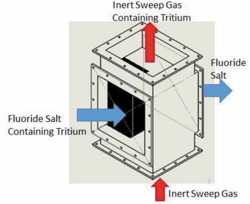
V.D.3.b. Double-Wall Heat Exchangers
Double-wall heat exchangers have been used in industry for many decades where heat transfer is required between highly reactive liquids. This type of heat exchanger has been considered for decades for flibe service in fission and fusion reactors. Heat and mass transfer follow similar laws; thus, a heat exchanger designed for transferring heat from salt to a second fluid is also good for transferring hydrogen to the surface of the heat exchanger and diffusion through the double-wall heat exchanger. The properties of flibe salt favor the use of fluted heat transfer tubes to improve heat transfer. This is because these salts have a low thermal conductivity relative to most other heat transfer fluids.
In the United States, most recent work on double-wall heat exchangers for flibe systems has been done at the University of MichiganCitation50,Citation51 and the University of California/Kairos Power. A schematic of a double-wall heat exchanger tube is in . Recent studies indicate that the sweep gas can capture 99.5% of the tritium going through the heat exchanger. Typically, the sweep gas is helium with its high thermal conductivity. There are also proposals to use a salt as the sweep fluid for tritium capture. Such a fluid would have a higher thermal conductivity and thus a more thermally efficient heat exchanger. There are plate-type heat exchangers that are equivalent to a double-tube heat exchanger. This may be a sufficient level of tritium removal for an FHR but would not be acceptable by itself for a fusion machine in terms of allowable tritium releases to the environment.
Fig. 12. Three-fluid design concept for a double-wall heat exchanger
There are a large number of design options for tritium removal with these systems, most of which have not been investigated in any detail. For example, the annular sweep gas could be helium with a small quantity of oxygen. Any tritium entering the annular zone would be oxidized to steam that does not diffuse through metal walls. However, oxide layers act as barriers to tritium diffusion. The oxygen would create a barrier to the diffusion of tritium from the flibe salt to the annular zone. Ideally one would want to coat the tube facing the flibe salt with a metal that did not oxidize to allow efficient transport of tritium into the annular zone to remove the tritium from the system.
V.D.3.c. Heat Pipes
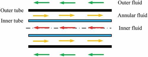
Sodium heat pipes are proposed to transfer heat from the flibe salt to the power cycleCitation52,Citation53 with three additional objectives: (1) isolate low-pressure flibe reactor system from high-pressure power cycle, (2) prevent accidental freezing of flibe salt, and (3) capture tritium. Each heat pipe () would have its bottom half in the flibe salt and its top half delivering heat to the power cycle, either (1) directly heating steam, supercritical carbon dioxide, or compressed air, or (2) heating a secondary heat transfer fluid such as a nitrate or chloride salt if heat storage is in the power cycle. The heat vaporizes the sodium that then flows as a gas to the colder condenser section of the heat pipe where it condenses to a liquid and flows back to the hot salt zone. The liquid salt and steam or air heat exchanger surfaces are separately designed for efficient heat transfer. The heat pipe is lined with a wick where capillary forces wet the entire heat pipe surface and move liquid sodium from the cold condenser section to the hot salt section where it is evaporated.
Fig. 13. Heat transfer regions within a heat pipe
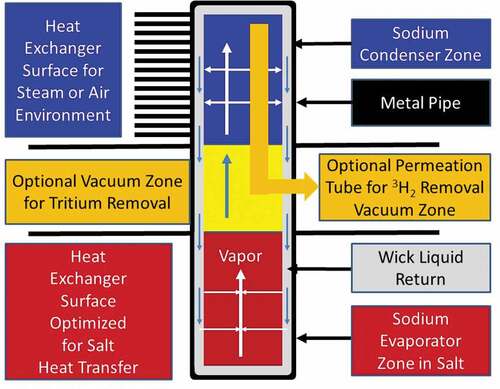
Heat pipe performance depends upon the vapor pressure of the sodium, which depends upon temperature. Sodium is chosen because at the melting point of flibe (459°C) the vapor pressure is very low resulting in almost no heat transfer. At 600°C the system is efficient at heat transfer. Heat pipes can be designed to turn on and shut off at defined temperatures. This characteristic can provide protection against freezing of the flibe salt.
The heat pipe can be designed to capture tritium. No tritium diffusion barriers are incorporated into the evaporator zone of the heat pipe to enable efficient tritium permeation from salt into the heat pipe. Inside the heat pipe the evaporation and movement of the sodium vapor sweeps noncondensable tritium to the condenser section. The condenser section includes barriers to tritium transfer such as tungsten electroplate on the inside of the heat pipe. Tritium is removed by a permeation membrane made of nickel or other highly permeable material to hydrogen. The permeation membrane may be either a tube inside the heat pipe that leads to a vacuum zone to collect the tritium or a section of the heat pipe wall that acts as a permeation membrane. Unlike a permeation membrane in salt, the required surface area for a permeation membrane in this system is very small. The sodium vapor sweeps the tritium into the condenser section. Diffusion of tritium through the sodium vapor is very fast relative to a liquid salt because the density of the vapor is three orders of magnitude less than the density of the salt. If a permeation membrane is part of the heat pipe wall, the area is small because the high solubility of hydrogen in sodium and the high diffusion coefficient of hydrogen in sodium relative to salt ( and ) implies high rates of hydrogen diffusion through the sodium to the permeation membrane.
Sodium heat pipes with permeation membranes to remove hydrogen have been designed for industrial and other applications but not for tritium removal. Heat pipes are being developed to remove heat from hydrogen-rich streams in chemical plants where a quarter or more of the gas stream may be hydrogen. In this environment sufficient hydrogen diffuses into the heat pipe to shut it down within days. The hydrogen is a noncondensable gas that is swept to the condenser section of the heat pipe and blocks sodium vapor transport. In these systems a permeation tube is added to remove hydrogen from the heat pipe. For these applications the hydrogen concentrations are many orders of magnitude greater than would be found in an FHR or ARC and there is no requirement to avoid some loss of hydrogen. Heat pipes have been built for decay heat removal from salt reactors but have not been designed for tritium blockage and recovery.
V.D.4. Removal of Tritium from Secondary Loop
V.D.4.a. Nitrate Salts (Chemically Oxidizing)
Kairos Power and most MSR startup companies propose a nitrate intermediate loop between the primary system containing flibe salt and the power cycleCitation27 to (1) isolate the low-pressure flibe system from the high-pressure power cycle, (2) act as a backup system for tritium capture and to prevent tritium release, and (3) operate as a heat storage system (Sec. VI). The nitrate salt is the solar salt used in existing CSP systems (not advanced Gen-III CSP systems) as a heat transfer and heat storage system. It can be used to transfer heat to industrial customers. Nitrate salt systems operate between 290°C and 600°C. With careful control or chemistry, it may be possible to increase the temperature to 650°C. Multiple CSP systems use these nitrate salts; thus, there is large-scale industrial experience in these salt systems including large-scale pumps and nitrate heat storage tanks that store gigawatt hours of heat.
Hot nitrate salts are highly oxidizing and thus create oxide layers with low permeability to tritium diffusion. These oxidizing salts will quickly oxidize any tritium to steam that can be collected in the off-gas system. Steam in an oxidizing environment will not diffuse through steel. An intermediate nitrate loop provides a trap for any tritium. This is the near-commercial option to assure no tritium escape. There has been only limited work on the steam recovery systems from the nitrate salt.
There are differences in the use of nitrate salts in intermediate loops with different salt reactors. In the FHR the nitrate salt loop may operate at a lower pressure than the flibe primary loop to avoid an oxidizing salt entering the reactor coolant and reacting with the carbon moderator in the event of a heat exchanger failure. A fusion flibe blanket may not have any carbon in the primary loop and thus this is not a concern. In a MSR the nitrate salt loop may be in a tertiary loop with a secondary loop operating at a higher pressure than the primary loop to avoid transport of fuel salt out of the primary loop in the event of a heat exchanger failure and any interactions of an oxidizing nitrate salt with the dissolved fuel and fission products. In a MSR changes in salt chemistry have the potential to precipitate fuel or fission products creating other safety concerns.
V.D.4.b. Halide Salts (Chemically Reducing)
Multiple halide salts are proposed for the intermediate loops of FHRs and MSRs. In terms of tritium, the common characteristic of all these salts is that tritium will be in the hydrogen form (3H2). This creates the potential for the tritium to enter the secondary salt system and then diffuse out of the salt system through piping or heat exchangers. These systems can use the same tritium removal systems as used in the primary loop (both chemically reducing chemistry) with some important differences. Permeation from the flibe salt into the secondary salt implies pure hydrogen in the secondary loop. There are no other radionuclides or HF. It is a clean system. Second, the secondary salts have much lower costs.
The combination of a lower-cost salt and no gamma dose reduces the design and cost constraints for any tritium removal systems including carbon beds and gas sparging systems in secondary systems. Options such as a large gas stripping tower with a fill material (secondary salt going downward with stripping gas going upward) may become attractive. There are several candidate salts, each with different characteristics:
Flinak: Flinak (LiF/NaF/KF) has been proposed for the secondary loop because it is compatible with flibe and is relatively nontoxic. For an FHR or MSR, the major question about Flinak is whether to use isotopically separated 7Li. If natural lithium is used, a small leak of Flinak into the primary system would shut down the reactor. This would be a much smaller concern in a fusion system where one burns out lithium at a significant rate to produce tritium and thus must include some system to readjust the lithium isotopics over time.
Potassium-zirconium fluoride: The nonlithium alternative to Flinak is a mixture of potassium and zirconium fluorides with relatively low cross sections to parasitic neutron capture.
Sodium-potassium-magnesium-chloride salts: The next-generation CSP system designsCitation13,Citation27 propose using a sodium-potassium-chloride salt with a melting point of ~420°C. It is extremely cheap and proposed for large-scale multigigawatt-hour heat storage systems. It is currently proposed to be used in the intermediate heat transfer loop of the TerraPower MCFR and would be a leading candidate for the intermediate loop of any other chloride salt reactor. To minimize corrosion, small amounts of magnesium metal are dissolved in the salt creating a chemically reducing environment. We are not aware of any studies of hydrogen transport and behavior in these systems.
V.D.4.c. Steam or Supercritical Carbon-Dioxide Power Cycle
The last tritium trapping system is the power cycle. If the cycle operates under oxidizing conditions, the power cycle can be a tritium trap. If it’s a steam cycle, then there is the challenge of tritium separation from large quantities of normal water because of rapid isotopic exchange of normal hydrogen and tritium in a hot water or steam environment. These options are reasonably well understood because this can happen in CANDU reactors. We are not aware of any assessment of trapping tritium in a supercritical carbon dioxide cycle where one only requires separating water from carbon dioxide.
V.E. Systems Design Analysis
The development of tritium removal systems requires a system analysis code that includes salt chemistry, corrosion, redox control, tritium capture systems, and tritium barriers. It is a systems question: (1) where and how tritium should be captured (from salt, in heat exchangers, in secondary loop), (2) the performance of permeation barriers, and (3) the redox control strategies that determine allowable materials of construction. For fusion machines the total tritium inventory determines the accident source term and thus creates large incentives to minimize total tritium inventory. The question is what set of options meets the requirements at the lowest cost with the required assurances for tritium recovery and low releases to the environment? TRIDENTCitation54,Citation55 and several other systems codes exist to address these questions.
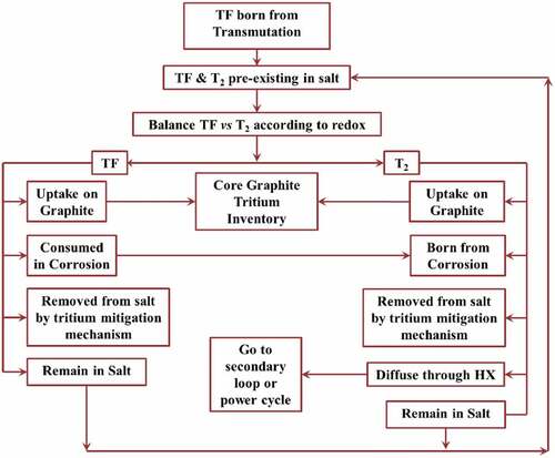
TRIDENT () models tritium generation by lithium transmutation; speciation based on chemical conditions (redox potential); absorption in reactor and structural materials including all components in the primary and secondary system; corrosion of structural materials; and convection and diffusion through the molten salt and the heat exchangers. It can’t be overemphasized that tritium behavior is controlled by chemical redox that controls the ratio of H2 to HF. Currently TRIDENT is equipped with the capability to simulate various tritium mitigation strategies including the use of an adsorption column, a gas sparging tower, and a permeation window, as well as using chemical control agents to limit the diffusion due to permeation of gaseous H2 (CitationRefs. 54 and Citation55). If a new technology is introduced, it must be added to these systems codes.
Fig. 14. Tritium mechanisms in TRIDENT
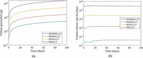
Previous analyses in TRIDENT using an adsorption bed found that the radioactive release of tritium from the reactor could be reduced by more than 90% using a graphite bed.Citation56,Citation57 With high-performance Calgon Carbon granular carbon OVC 4 × 8, from Sec. V.D.1.c, the solubility of carbon adsorbents can be increased by an order of magnitude, significantly reducing the total radioactive release.Citation43,Citation46 Using TRIDENT, a countercurrent carbon adsorption bed with carbon OVC 4 × 8 is simulated at different 7Li concentrations in the 236-MW(thermal) prototypical FHR (). Columns of different sizes were examined resulting in four different average tritium generation rates: 2670 Ci/day for 99.995% 7Li (design case for FHR), 24 140 Ci/day for 99.95% 7Li, 238 430 Ci/day for 99.5% 7Li, and 2 450 070 Ci/day for 95% 7Li enrichment. In an FHR the lithium enrichments are above 99.99% 7Li, but lower lithium enrichments are used in this example to demonstrate how system performance changes as tritium production increases, as in a fusion system. The maximum release rate is found to be 40 Ci/day for 99.995% 7Li (design case for FHR), 1440 Ci/day for 99.95% 7Li, 25 240 Ci/day for 99.5% 7Li, and 300 860 Ci/day for 95% 7Li enrichment. An order of magnitude increase in production is accompanied by an order of magnitude increase in the tritium release rates as the limits of tritium solubility are reached with a fixed system size and rate of carbon regeneration. The time-dependent behavior reflects the burnout of 6Li over time in an FHR.
Fig. 15. (a) Cumulative tritium generation in 236-MW(thermal) FHR at different 7Li enrichments of 95%, 99.5%, 99.95%, and 99.995%, and (b) tritium capture on carbon bed at different concentrations
To illustrate the mitigation challenges of high tritium generation, the size of the adsorption column required for an FHR at 99.5% 7Li enrichment is examined. At 99.5% 7Li, the system has two orders of magnitude greater tritium generation than the base-case FHR. The surface area of the bed previously modeled is increased (by increasing bed length) and the corresponding release rates are shown in .
Fig. 16. (a) Release rate during operation at different bed surface areas (1x, 2x, 4x, 8x surface area compared to a bed sized 1.5 m R × 4.5 m H filled with 0.9-cm pebbles), and (b) peak release versus the bed surface area
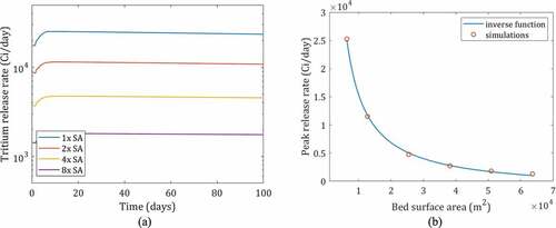
An inverse (1/x) relationship is found between the surface area and release rate as shown in . When the surface area is doubled from the original bed, the release rate decreased from 25 243 to 11 490 Ci/day. At the extreme case of 10x bed size, the peak release was found to be 1301 Ci/day, which is still an order of magnitude greater than any existing fission reactor in operation today. Thus, the costs of mitigating tritium releases in fusion devices will be much greater than for highly 7Li–enriched fission systems unless there is a step change improvement in mitigation technology.
What such system models show is that there are multiple existing options to control tritium releases from an FHR. Existing technologies can efficiently recycle tritium in a fusion machine. The challenge is minimizing tritium releases from a fusion machine to the environment where the allowable releases are about one part in a hundred thousand with a system of reasonable size and cost. The loss of a small fraction of 1% of the tritium is not important in terms of fusion tritium breeding but is important in terms of releases to the environment. If one does not efficiently remove the tritium from the salt before the hot salt goes through the high-surface-area heat exchanger, small amounts of tritium relative to the inventory in the salt leak through the heat exchangers, but above allowable releases. Further reductions may need a combination of high-efficiency capture technology (possibly vacuum disengagers), chemical species control of the tritium to limit H2 escape (such as a nitrate intermediate loop or oxygen getter in double-wall heat exchangers that oxidizes tritium to prevent diffusion through metals), or additional barriers to hinder diffusion (such as a heat pipe with permeation membrane or better permeation barriers). Improvements in any of these domains is beneficial for both fusion and fission systems.
V.F. Equipment
There is equipment experience with flibe salt. The 8-MW(thermal) Molten Salt Reactor Experiment (MSRE) in the late 1960s operated successfully using an overhung centrifugal pump to circulate the primary salt and clean flibe in the secondary loop. The motor was in the air with the centrifugal pump below the motor. There were no major difficulties with these pumps beyond some leakage of oil from seals above into the salt. SINAP plans to operate a small MSR within the next 2 years and has a pump development program.
Today CSP towers use centrifugal pumps to pump nitrate salts at temperatures that approach 600°C (CitationRef. 27). The experience with these pumps has been excellent. However, hot nitrate salts are compatible with air and water whereas flibe salt is not. The next generation CSP systems (Gen-III systemsCitation13,Citation27) plan to use sodium-potassium-magnesium-chloride salts that require chemically reducing conditions and will operate in the temperature range of 450°C to 750°C. The base-case redox control agent for these chloride salts is magnesium metal dissolved in the chloride salt versus beryllium metal dissolved in flibe salt. These conditions are similar to those required for a flibe salt system. A pilot plant is expected to be built within the next 5 years. Work is required to develop large flibe pumps with massive overlap in requirements to pumps required for Gen-III CSP systems.
The MSRE program began to develop valves using graphite gaskets for flibe salt operations. These were never deployed. Freeze valves were highly successful and thus the valve program was a low priority. We have not identified other industries that have developed valves that would be fully compatible with flibe service, but we have not undertaken any extensive effort to determine if such valves exist in other industrial sectors.
VI. MARKET CHALLENGES AND IMPLICATIONS FOR FLIBE SYSTEMS
VI.A. Heat Storage
The electricity market is changing because of (1) the goal of a low-carbon electricity grid and (2) the addition of wind and solar. The large-scale addition of wind and solar results in highly volatile prices with times of low or negative prices and other times of high prices, depending on wind or solar conditions. The goal of a low-carbon grid requires new energy systems that can economically provide the three services of fossil fuels: (1) energy production, (2) energy storage, and (3) dispatchable electricity.
Adding heat storage to nuclear power plants enables nuclear power plants to (1) boost revenue in markets with large-scale wind and solar and (2) replace fossil fuels in providing dispatchable electricity including assured peak generating capacity while operating the reactor at base load. A recent workshopCitation27 addressed gigawatt-hour heat storage coupled to Gen-IV nuclear reactors with the participation of developers of Gen-III CSP systems. The changes in the market may drive power cycle changes. This has additional implications for fusion. First, fusion reactors operate in a pulse mode. In an inertial fusion machine this pulse mode may be a fraction of a second whereas in the magnetic fusion machines it may be many hours. Heat storage allows the fusion machine to operate in its most efficient mode without considering the implications for the grid. Second, as discussed above, many heat exchanger and heat storage systems will act to stop tritium escape to the environment. There is no requirement for the fusion community to separately develop technologies to address these challenges. shows the system design for heat storage coupled to any large-scale heat source—fission or fusion.
Fig. 17. System design for heat storage coupled to a nuclear reactor
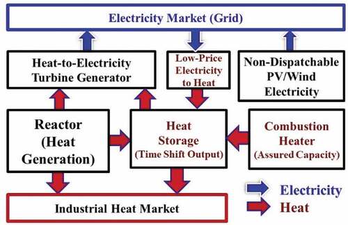
To minimize the cost of electricity, capital-intensive generating assets (fission, wind, solar, and fusion) should operate near their maximum capacity. Using this system, when electricity prices are high all reactor heat is sent to the turbine to produce electricity. When electricity prices are low, most heat is diverted to heat storage. At times of peak electricity prices, heat from the reactor and heat storage is sent to the turbine for peak electricity production that is significantly above base-load reactor electricity output. Peak electricity production can be achieved by (1) oversizing the turbine generator or (2) building a separate peaking steam or gas turbine for peak power output. At times of very low electricity prices, electricity from the grid and from the main turbine operating at minimum load is converted into stored heat with resistance heaters coupled to the heat storage system. The power plant becomes a seller and buyer of electricity. If heat storage is depleted, natural gas or low-carbon biofuels and hydrogen are used to enable assured peak electricity production by providing the extra heat that would have come from the heat storage system.
This has large economic implications for the economics of salt power systems. The cost of heat storage is a strong function of the average delivered peak temperature. First, the cost of heat storage depends on the temperature range in the heat storage system. If that temperature range is doubled, heat storage costs are cut in half. Second, the heat-to-electricity efficiency is a strong function of peak temperatures. The higher temperatures of salt systems imply much smaller heat storage per unit of electricity production. shows the temperature of delivered heat from different nuclear systems. The implication is that a salt-cooled system will have an economic advantage relative to power systems that use lower-temperature coolants if heat storage is required to meet market needs.
The primary heat storage materials used today in CSP systems are nitrate salts with solar salt (solar salt: 60 wt% NaNO3–40 wt% KNO3) the most common salt. These salts are chemically stable in air and water. Sensible heat of storage is obtained by typically varying temperatures from 290°C to 565°C. CSP salts need reasonable margins from decomposition temperatures to avoid hot spots in solar collectors that can degrade the salt. With control of gas compositions over the salt storage tanks and salt chemistry, salt storage temperatures in the 600°C to 650°C range may be possible. If the salt system is used for backup tritium recovery, the off-gas system must recover tritiated steam. Heat storage system capital costs in CSP systems are near $20/kWh(thermal) or $50/kWh(electric), about an order of magnitude less than battery storage systems. The largest storage system sizes are measured in gigawatt hours of capacity. Nitrate salts can be used to move heat to industrial customers.
Nitrate salt storage systems are proposed for SFRs (TerraPower), FHRs (Kairos Power) with solid fuel and clean salt coolants, thermal-spectrum MSRs with fuel dissolved in the salt, HTGRs, and fusion machines.
Work is underway to develop the next generation of salt systems that will allow CSP systems (Gen-III) to operate at peak temperatures of ~750°C with higher-temperature stored heat. The proposed salt is a sodium-potassium-magnesium eutectic with a melting point near 400°C. This salt was chosen because of its extremely low cost combined with reasonable physical properties, primarily the melting point. Allowable peak salt operating temperatures could exceed 1000°C. These salts are similar to the salts that are used to produce magnesium in electrochemical cells; thus, there is overlap in technology with the magnesium industry. The chloride storage salts are proposed to be used with MCFRs (TerraPower) with reactor peak temperatures near 750°C. The chloride storage salts would couple to flibe fission and fusion systems. There is also work on carbonate salts but at a lower level of effort.
VI.B. Plant Architecture
Heat storage may change reactor power plant system design with the reactor facility inside a security zone that includes all vital areas for reactor safety and the storage and power blocks outside this security zone. shows the plant layout for a CSP or nuclear plant using salt storage with this configuration. In CSP systems, heat storage simplifies operation. On partly cloudy days the power output of a CSP system varies depending on whether the clouds are blocking the sun. With storage, the power block does not see such transients and thus storage simplifies operations. Cold salt to the CSP system always comes from storage whereas hot salt to the power block can come from storage or the CSP system. The same design can be used for a nuclear power plant as proposed by TerraPower for sodium and salt reactors. TerraPower proposes using nitrate salts to couple with its SFRs and chloride salts to couple to its MCFR.
Fig. 18. System design for CSP and nuclear with storage
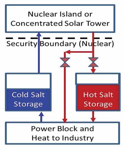
Current reactors put the power block (turbine generator) next to the reactor—a design that followed the design of earlier coal-fired power stations and that was developed before tight security requirements for nuclear power plants. The separation of the reactor and vital areas from the power block creates a clear division between areas with (1) requirements for nuclear security, maintenance, licensing, safety, and construction versus (2) normal industrial requirements. This has the potential to reduce costs. Second, gigawatt-hour heat storage systems may become the largest set of structures on site. They will be in the protected area that has industrial safety and security requirements but in some cases may need to be some distance (100 m) from reactor vital areas. Heat storage systems such as hot salt storage tanks may need to be some distance away because their failure would create a thermally hot area that could damage buildings and equipment next to such tanks. Last, storage isolates the reactor from the electricity grid and reduces transients from the grid to reactor and reactor to grid. The reactor becomes a heat generation system.
VI.C. Power Cycles
Salt reactors can be coupled to different power cycles. Steam cycles are the near-term option. The longer-term option is coupling salt reactors to NACCs with heat storage and a thermodynamic topping cycle. This power cycle enables a base-load reactor to provide variable electricity to the grid and can potentially replace natural gas combined cycle plants. Recent papersCitation20,Citation58 describe this technology.
Molten salt reactors were originally developed in the 1950s as part of the Nuclear Aircraft Propulsion program where the goal was to build a jet aircraft with unlimited range. That is, MSRs were chosen because of their ability to efficiently couple to Brayton power cycles. In the 1950s gas turbines were inefficient, but 60 years of development have resulted in dramatic improvements in gas turbine efficiency. Salt reactors have two characteristics that enable efficient coupling to Brayton power cycles. First, in modern gas turbines air is compressed to between 350°C and 450°C. Any heat source to couple to NACCs must provide heat above this temperature. Salt reactors typically have minimum salt temperatures near 600°C (). Second, salt reactors deliver heat at a higher average temperature than other reactor technologies. Significant development is required.
VII. CONCLUSIONS
Research, development, demonstration, and funding for fission, fusion, and CSP have historically been done by different organizations with results reported in separate journals and different conferences. Technical developments in fission (FHRs, MCFRs), fusion (ARC), and CSP (Gen-III) combined with changes in electricity markets (heat storage) in the last 5 years have resulted in massive technology overlap of high-temperature salt-cooled power systems. Going forward this creates large incentives for cooperative programs across energy sources.
The ARC and FHR use clean flibe as a coolant. This results in an overlap in technology needs for both systems and creates large incentives for cooperative programs between fission and fusion to accelerate the development of these two technologies. Flibe blankets are being considered for other fusion machines, and flibe is proposed for several types of MSRs with fuel dissolved in the salt. In all of these machines there is a strong coupling of salt properties, heat transfer, tritium control, and material choices. The salts in fluoride and chloride salt systems all have high melting points implying common challenges to prevent salt freezing and similar or identical heat storage and power cycles. The high temperatures of operation and the need for chemically reducing conditions to limit corrosion imply many similarities in materials selection. The salt fission, fusion, and CSP programs are not in direct competition but rather strategic partners in advanced energy systems.
Acknowledgments
We would like to thank ENI, the U.S. Department of Energy, and the SINAP for their support. We would like to thank the following individuals for their input and review comments: T. J. Dolan (University of Illinois), R. Moir (Lawrence Livermore National Laboratory, Retired), P. Peterson (Kairos Power/University of California at Berkeley), X. Sun (University of Michigan), and M. Driscoll (MIT).
Additional information
Funding
Notes
a ENI is one of the big-five western oil companies.
Related Research Data
References
- B. N. SORBOM et al., “ARC: A Compact, High-Field, Fusion Nuclear Science Facility and Demonstration Power Plant with Demountable Magnets,” Fusion Eng. Des., 100, 378 (Nov. 2015); https://doi.org/10.1016/j.fusengdes.2015.07.008.
- A. Q. KUANG et al., “Conceptual Design Study for Heat Exhaust Management in the ARC Fusion Pilot Plant,” Fusion Eng. Des., 137, 221 (Dec. 2018); https://doi.org/10.1016/j.fusengdes.2018.09.007.
- C. J. BARTON and R. A. STRELOW, “Blankets for Thermonuclear Reactors,” ORNL-3258, Oak Ridge National Laboratory (1962).
- W. R. GRIMES and S. CANTOR, “Molten Salts as Blanket Fluids in Controlled Fusion Reactors,” ORNL-TM-4047, Oak Ridge National Laboratory (1972).
- J. A. BLINK et al., “The High-Yield Lithium-Injection Fusion-Energy (HYLIFE) Reactor,” Lawrence Livermore National Laboratory (1985); https://www.osti.gov/servlets/purl/6124368 (current as of Sep. 12, 2019).
- R. W. MOIR et al., “HYLIFE-II: A Molten-Salt Inertial Fusion Energy Power Plant Design—Final Report,” Fusion Technol., 25, 1, 5 (1994); https://doi.org/10.13182/FST94-A30234.
- A. SAGARA et al., “Blanket and Divertor Design for Force Free Helical Reactor (FFHR),” Fusion Eng. Des., 29, 51 (1995); https://doi.org/10.1016/0920-3796(95)80005-I.
- L. C. CADWALLADER and G. R. LONGHURST, “Flibe Use in Fusion Reactors: An Initial Safety Assessment,” INEEL/EXT-99-00331, Idaho National Engineering and Environmental Laboratory (Mar. 1999); https://doi.org/.
- R. W. MOIR, “Flibe Coolant Cleanup and Processing in the HYLIFE-II Inertial Fusion Energy Power Plant,” UCRL-ID-143228, Lawrence Livermore National Laboratory (2001).
- A. SAGARA et al., “Conceptual Design Activities and Key Issues on LHD-Type Reactor FFHR,” Fusion Eng. Des., 81, 23–24, 2703 (Nov. 2006); https://doi.org/10.1016/j.fusengdes.2006.07.057.
- Molten Salt Reactors and Thorium Energy, T. J. DOLAN, Ed., Woodhead Publishing Series in Energy, Elsevier Ltd (2017).
- E. MERLE, “Concept of European Molten Salt Fast Reactor (MSFR),” CNRS-IN2P3-LPSC/Grenoble Institute of Technology/UGA—France (May 23, 2017); https://www.gen-4.org/gif/upload/docs/application/pdf/2017-05/emerle_gif-final23may2017.pdf (current as of Sep. 12, 2019).
- M. MEHOS et al., “Concentrated Solar Power Gen3 Demonstration Roadmap,” NREL/TP-5500-67464, National Renewable Energy Laboratory (Jan. 2017); https://www.nrel.gov/docs/fy17osti/67464.pdf (current as of Sep. 12, 2019).
- M. ABDOU et al., “Blanket/First Wall Challenges and Required R&D on the Pathway to DEMO,” Fusion Eng. Des., 100, 2 (Nov. 2015); https://www.sciencedirect.com/science/article/pii/S0920379615302465 (current as of Sep. 12, 2019).
- M. E. SAWAN et al., “Neutronics Assessment of Molten Salt Breeding Blanket Design Options,” presented at 16th Topl. Mtg. Fusion Energy, Madison Wisconsin, September 14–16, 2004; UWFDM-1234, University of Wisconsin (Sep. 2004); http://fti.neep.wisc.edu/pdf/fdm1234.pdf (current as of Sep. 12, 2019).
- M. GREENWALD et al., “Parameter Sensitivities and Physics Optimization for SPARC-V1C, APS-DPP,” (Oct. 21, 2019); https://www.aps.org/units/dpp/meetings/annual/ (current as of Sep. 12, 2019).
- D. BRUNNER, “Overview of SPARC on the High-Field Path to Fusion Energy, APS-DPP,” (Oct. 21, 2019); https://www.aps.org/units/dpp/meetings/annual/ (current as of Sep. 12, 2019).
- C. W. FORSBERG and P. F. PETERSON, “Basis for Fluoride Salt-Cooled High-Temperature Reactors with Nuclear Air-Brayton Combined Cycles and Firebrick Resistance Heated Energy Storage,” Nucl. Technol., 196, 13 (Oct. 2016); https://doi.org/10.13182/NT16-28.
- C. W. FORSBERG et al., “Integrated FHR Technology Development: Tritium Management, Materials Testing, Salt Chemistry Control, Thermal Hydraulics and Neutronics, Associated Benchmarking and Commercial Basis,” MIT-ANP-TR-180, Massachusetts Institute of Technology, (Oct. 2018); https://www.osti.gov/search/semantic:1485415 (current as of Sep. 12, 2019).
- C. ANDREADES et al., “Design Summary of the Mark-I Pebble-Bed Fluoride Salt-Cooled, High-Temperature Reactor Commercial Power Plant,” Nucl. Technol., 195, 223 (Sep. 2016); https://doi.org/10.13182/NT16-2.
- R. R. ROMATOSKI and L. W. HU, “Fluoride Salt Coolant Properties for Nuclear Reactor Applications: A Review,” Ann. Nucl. Energy, 109, 635 (2017); https://doi.org/10.1016/j.anucene.2017.05.036.
- R. R. ROMATOSKI and L. W. HU, “Fluoride-Salt-Cooled High-Temperature Test Reactor Thermal-Hydraulic Licensing and Uncertainty Propagation Analysis,” Nucl. Technol., 205, 1495 (2019); https://doi.org/10.1080/00295450.2019.1610686.
- “Oak Ridge Molten Salt Workshop,” Oak Ridge National Laboratory (2019); https://msrworkshop.ornl.gov/ (current as of Sep. 12, 2019).
- Y. ZENG et al., “Tritium Transport Analysis in a 2-MW Liquid-Fueled Molten Salt Experimental Reactor with the Code TMSR-TTAC,” Nucl. Technol., 205, 4, 582 (2019); https://doi.org/10.1080/00295450.2018.1507200.
- B. FENG et al., “Core and Fuel Cycle Performance of a Molten Salt Fast Reactor,” Int. Congress on Advances in Nuclear Power Plants (ICAPP 2019), Juan les Pins, France, May 12–15, 2019.
- C. FORSBERG et al., “Flibe Fusion Blankets and Flibe Fluoride-Salt-Cooled High-Temperature Reactors: Opportunities for Synergistic Development Strategies,” Proc. American Nuclear Society Winter Meeting, Washington, District of Columbia, November 17–21, 2019.
- C. W. FORSBERG, H. GOUGAR, and P. SABHARWALL, “Heat Storage Coupled to Generation IV Reactors for Variable Electricity from Base-Load Reactors: Workshop Proceedings,” Proc. ANP-TR-185, Center for Advanced Nuclear Energy Systems, Massachusetts Institute of Technology, July 23–24, 2019; INL/EXT-19-54909, Idaho National Laboratory (2019).
- S. SMOLENTSEV et al., “MHD Thermohydraulics Analysis and Supporting R&D for DCLL Blanket in the FNSF,” Fusion Eng. Des., 135, 314 (2018); https://doi.org/10.1016/j.fusengdes.2017.06.017.
- S. SMOLENTSEV et al., “An Approach to Verification and Validation of MHD Codes for Fusion Applications,” Fusion Eng. Des., 100, 65 (2015); https://doi.org/10.1016/j.fusengdes.2014.04.049.
- C. COYLE, E. BAGLIETTO, and C. FORSBERG, “Advancing Radiative Heat Transfer Modelling in High-Temperature Liquid Salts,” 18th Int. Topl. Mtg. Nuclear Reactor Thermal Hydraulics (NURETH-18), Portland, Oregon, August 18–23, 2019.
- N. ZWEIBAUM, “Experimental Validation of Passive Safety System Models: Application to Design and Optimization of Fluoride-Salt-Cooled, High-Temperature Reactors,” PhD Dissertation, University of California, Berkeley (2015); https://escholarship.org/uc/item/744882bt (current as of Sep. 12, 2019).
- C. W. FORSBERG et al., “Tritium Control and Capture in Salt-Cooled Fission and Fusion Reactors: Status, Challenges, and Path Forward,” Nucl. Technol., 197, 119 (Feb. 2017); https://doi.org/10.13182/NT16-101.
- J. ZHANG et al., “Redox Potential Control in Molten Salt Systems for Corrosion Mitigation,” Corros. Sci., 144, 44 (2018); https://doi.org/10.1016/j.corsci.2018.08.035.
- E. T. CHENG, H. J. MERRIL, and D.-K. SZE, “Nuclear Aspects of Molten Salt Blankets,” Fusion Eng. Des., 69, 205 (2003); https://doi.org/10.1016/S0920-3796(03)00339-9.
- H. MORIYAMA et al., “Molten Salts in Fusion Nuclear Technology,” Fusion Eng. Des., 39-40, 627 (1998); https://doi.org/10.1016/S0920-3796(98)00202-6.
- K. R. BRITSCH and M. ANDERSON, “A Critical Review of Fluoride Salt Heat Transfer,” Nucl. Technol., 206, 1625 (2020); https://doi.org/10.1080/00295450.2019.1682418.
- S. FUKADA et al., “Reaction Rates of Beryllium with Fluorine Ion for Flibe Redox Control,” J. Nucl. Mater., 367-370, Part B, 1190 (Aug. 1, 2007); https://doi.org/10.1016/j.jnucmat.2007.03.218.
- B. J. RILEY et al., “Molten Salt Reactor Waste and Effluent Management Strategies: A Review,” Nucl. Eng. Des., 345, 94 (2019); https://doi.org/10.1016/j.nucengdes.2019.02.002.
- T. TANABE et al., “Hydrogen Transport in Stainless Steels,” J. Nucl. Mater., 123, 1568 (1984); https://doi.org/10.1016/0022-3115(84)90304-0.
- A. NAKAMURA, S. FUKADA, and R. NISHIUMI, “Hydrogen Isotopes Permeation in a Fluoride Molten Salt for Nuclear Fusion Blanket,” J. Plasma Fusion Res., 11, 25 (2015); https://pdfs.semanticscholar.org/4d8c/d2273bd3e3a99129105ea7e1bc5d6edcaecb.pdf (current as of Sep. 12, 2019).
- R. A. CAUSEY, R. A. KARNESKY, and C. SAN MARCHI, “4.16—Tritium Barriers and Tritium Diffusion in Fusion Reactors,” Comprehensive Nuclear Materials, R. J. M. KONINGS, Ed., pp. 511–549, Elsevier, Oxford (2012).
- J. TROUVE and G. LAFLANCHE, “Hydrogen Diffusion and Permeation in Sodium,” presented at Int. Conf. Liquid Metal Engineering and Technology in Energy Production (CEA-CONF-7645), Oxford, United Kingdom, April 9–13, 1984.
- S. T. LAM, R. BALLINGER, and C. FORSBERG, “Modeling and Predicting Total Hydrogen Adsorption on Porous Carbon Materials,” J. Nucl. Mater., 511, 328 (Dec. 1, 2018); https://doi.org/10.1016/j.jnucmat.2018.09.009.
- T. ATSUMI and M. MIYAKE, “Absorption and Desorption of Deuterium on Graphite at Elevated Temperatures,” J. Nucl. Mater., 155–157, Part 1, 241 (1988); https://doi.org/10.1016/0022-3115(88)90247-4.
- T. DOLAN, G. R. LONGHURST, and E. G. OTERO, “A Vacuum Disengager for Tritium Removal for HYLIFE-II Reactor Flibe,” Fusion Technol., 21, 3P2B, 1949 (May 1992); https://doi.org/10.13182/FST21-1949.
- S. LAM et al., “Weak and Strong Hydrogen Interactions on Porous Carbons Materials in High-Temperature Systems,” J. Nucl. Mater., 519, 173 (2019); https://doi.org/10.1016/j.jnucmat.2019.03.036.
- C. W. FORSBERG and P. F. PETERSON, “FHR, HTGR, and MSR Pebble-Bed Reactors with Multiple Pebble Sizes for Fuel Management and Coolant Cleanup,” Nucl. Technol., 205, 5, 748 (2019); https://doi.org/10.1080/00295450.2019.1573619.
- X. WU et al., “Mass Transport Analysis for Tritium Removal in FHRs,” Ann. Nucl. Energy, 121, 250 (2018); https://doi.org/10.1016/j.anucene.2018.07.026.
- X. WU et al., “Primary Design of a Tritium Control System for Fluoride-Salt-Cooled High-Temperature Reactor Systems,” Tritium, Charleston, South Carolina, April 17–22, 2016.
- S. ZHANG et al., “A Coupled Heat Transfer and Tritium Mass Transport Model for a Double-Wall Heat Exchanger Design for FHRs,” Ann. Nucl. Energy, 122, 328 (2018); https://doi.org/10.1016/j.anucene.2018.08.039.
- S. ZHANG et al., “Double-Wall Natural Draft Heat Exchanger Design for Tritium Control in FHRs,” Proc. 2017 25th Int. Conf. Nuclear Engineering (ICONE25), Shanghai, China, July 2–6, 2017.
- C. FORSBERG et al., “Fluoride-Salt-Cooled High-Temperature Reactor (FHR) Using British Advanced Gas-Cooled Reactor (AGR) Refueling Technology and Decay-Heat Removal Systems that Prevent Salt Freezing,” Nucl. Technol., 205, 9, 1127 (Apr. 2019); https://doi.org/10.1080/00295450.2019.1586372.
- B. ZOHURI et al., “Heat-Pipe Heat Exchangers for Salt-Cooled Fission and Fusion Reactors to Avoid Salt Freezing and Control Tritium: A Review,” Nucl. Technol., 206, 1642 (2020); https://doi.org/10.1080/00295450.2019.1681222.
- J. D. STEMPIEN, “Tritium Transport and Corrosion Modeling in the Fluoride Salt-Cooled High-Temperature Reactor,” PhD Thesis, Massachusetts Institute of Technology (2015).
- S. T. LAM, “Managing Tritium Inventory and Release with Carbon Materials in a Fluoride Salt-Cooled High-Temperature Reactor,” SM Thesis, Massachusetts Institute of Technology (2017).
- S. T. LAM et al., “Tritium Management and Control Using Carbon in a Fluoride-Salt-Cooled High-Temperature Reactor,” Fusion Sci. Technol., 71, 4, 644 (2017); https://doi.org/10.1080/15361055.2017.1290945.
- C. FORSBERG, J. STEMPIEN, and R. BALLINGER, “Tritium Removal from Salt-Cooled Reactors Using Carbon,” Proc. American Nuclear Society Winter Meeting, Washington, District of Columbia, November 8–12, 2015.
- C. W. FORSBERG, P. J. McDANIEL, and B. ZOHURI, “Base-Load Nuclear and Concentrated Solar Power (CSP) Air-Brayton Power Cycles with Thermodynamic Topping Cycles and Heat Storage for Variable Electricity and Heat,” Proc. ICAPP 2020, Abu Dhabi, United Arab Emirates, March 15–19, 2020.