
Abstract
The Kilopower reactors have been designed to provide a steady-state thermal power range between 4 and 40 kW and to convert the heat generated to an electrical output of 1 to 10 kW(electric), providing an overall system efficiency of 25%. This range of thermal and electrical power has been derived from two basic designs: the small 1-kW(electric) design and the larger 10- kW(electric) electric design intended to support science and human exploration missions for surface and in-space power. The Kilowatt Reactor Using Stirling TechnologY (KRUSTY) experiment was built using the 1-kW(electric) Kilopower design to make the test affordable by using existing infrastructure and to complete it in a 3-year timeframe. The data from the smaller, lower-mass system could be extended to the larger 10-kW(electric) system, knowing that the materials and neutronic design are similar. Each of these designs use the same fuel, heat transport systems, and power conversion systems at the appropriate scale to produce the desired electrical output power for mission use. The heat transport system uses multiple heat pipes that operate passively and do not require any electrical pumps or other parasitic loads to cool the reactor core. This type of reactor cooling provides several layers of redundancy and makes it ideal for coupling a self-regulating reactor to a variable-output power conversion system. The power converters accept the reactor heat that has been delivered by the heat pipes and create the needed electrical power through their thermodynamic Stirling cycle and linear alternator. This paper provides details about the sodium heat pipes used in the experiment, the Stirling power converters that create the electricity, and the overall power system that make up the 1-kW(electric) Kilopower reactor.
I. KILOPOWER AND KRUSTY POWER SYSTEM
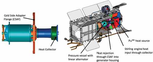
The 1-kW(electric) Kilopower reactor flight concept was the baseline design used for the Kilowatt Reactor Using Stirling TechnologY (KRUSTY) experiment as shown in . The materials and scale of all the components were sized to generate enough thermal power to be able to produce 1 kW(electric) of electric power for 15 years. The flight system was designed for eight independent strings of heat pipes, Stirling converters with balancers, and heat rejection radiators to create a highly redundant system. Each converter would need to be sized to produce at least 125 W of electrical power using roughly 375 W of thermal power in order to produce the 1 kW of total electrical power from all eight converters. The reactor will need to produce at least 3000 W of thermal power for power conversion plus the thermal losses between the core and power conversion system. Using this logic with some margin, the core was designed to produce approximately 4000 W of steady-state thermal power at 800°C for the 1-kW(electric) system. This design will allow the fuel to operate at these conditions for 15 years at only 0.1% fuel burnup. Any fuel burnup of <0.5% should ensure that fission gas and fuel swelling will not be a failure mechanism in the design. Higher powers for shorter durations can be accomplished for specific missions, but heat flux limitations and temperature drops in the smaller system could become inefficient to a point of diminishing returns.
Fig. 1. (a) Kilopower 1-kW(electric) reactor flight concept and (b) KRUSTY test hardware comparison showing several similarities and components.
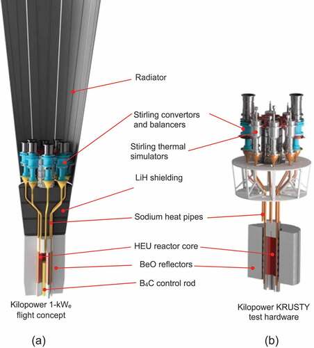
For the KRUSTY test, only two 80-W(electric) class Stirling converters were used because of the lack of funding and time associated with building eight of the correctly sized units. In order to effectively draw the necessary amount of thermal power from the heat pipes and core, six Stirling thermal simulators were used as replacements. These simulators were sized to be able to draw over 600 W of thermal power from each coupled heat pipe. These six thermal simulators along with the two Stirling converters () provided a controlled thermal load for the reactor. The thermal load was varied by either changing the Stirling convertor piston amplitude or the thermal simulator gas flow rate. Together, all eight units were capable of ramping the power conversion thermal load from zero power to full power, allowing the reactor to demonstrate its ability to passively follow and adjust to a wide range of user loads.
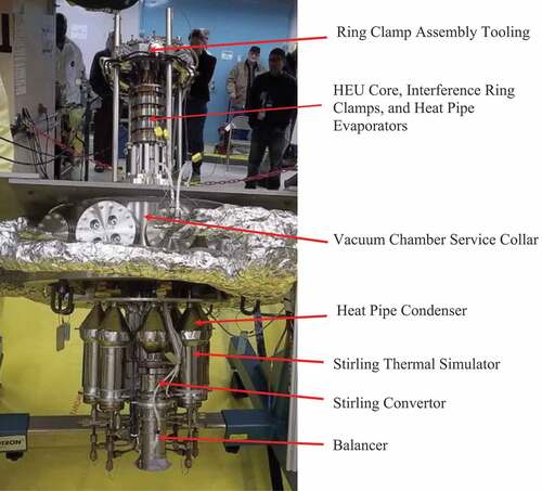
Fig. 2. KRUSTY test hardware shown upside down with labeled components.
The basic principle of the test was to start up the reactor, operate at nominal steady-state conditions, and then vary the power conversion system to demonstrate the reactor’s ability to passively self-regulate its temperature and thermal power output. The 28 h of reactor operations along with general descriptions of each phase of the test can be reviewed in David Poston’s journal papers as well as past papers.Citation1–Citation3 This paper describes in more detail the power conversion and heat transfer components of the Kilopower reactors and KRUSTY.
I.A. Heat Pipe Design
The heat pipes being designed for the Kilopower reactors have several mission environments that they could encounter. In-space power, lunar surface power, and Mars surface power are possible near-term missions that have different challenges regarding environmental variables. The primary environmental challenge when designing heat pipes is the gravitational environment. Gravity can have a major impact on the design of the heat pipe and its ability to meet the mission performance and operational goals. For in-space power, a microgravity heat pipe is needed, and the design and construction can be significantly different than a heat pipe that will operate on a planetary surface like the moon or Mars. The best-case scenario is a heat pipe that can operate at gravity levels between microgravity and Earth’s gravity to fully encompass all operating conditions between the two, including lunar and Martian conditions. This multimission heat pipe would allow the reactor to serve several missions without the heat pipes having to be redesigned. Creating a design that can achieve the performance goals in all these environments is difficult and has not been demonstrated to date. Heat pipe designs that are focused on each independent mission and gravity environment are more achievable, and current state-of-the-art methods are capable of providing solutions. These environmental requirements have not been fully established and actual missions have not been approved at this time. For this reason, specific gravitational requirements have not been formally issued for the Kilopower reactors and were not levied during the KRUSTY test.
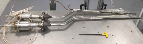
For the KRUSTY heat pipes (), it was determined that wickless heat pipes, or thermosyphons, would be used as they would adequately meet the performance goals for the test without adding the complexity of a wick. Although the wickless term is used, the KRUSTY heat pipes did have screen wicks in the evaporator to increase distribution and vaporization on the heated surfaces. The condensed sodium relied on gravity to move the fluid from the condenser region at the Stirling convertor interface to the evaporator region at the core by flowing down the bare internal walls of the heat pipe. Using wickless heat pipes is an option when considering Kilopower for planetary surface power systems as gravity levels may be adequate to provide the necessary fluid return flow to the evaporator.
Fig. 3. Two KRUSTY heat pipes attached to two Stirling thermal simulators that completed thermal performance testing and are in the middle of multilayer insulation fabrication.
When considering a wick design for higher-performance heat pipes, the use of arteries becomes increasingly necessary, as they provide increased mass flow of the sodium coolant back to the reactor core with minimal pressure drop to improve overall thermal throughput. These artery designs have several challenges regarding their ability to keep fluid within the artery over several gravity environments, including Earth-based testing. Some of the early prototype wick designs tested for Kilopower had issues regarding artery depriming when used in Earth’s gravity in the vertical orientation. This happens when gravity creates a pressure head on the fluid in the vertical artery that is greater than the capillary forces needed to hold the fluid in the arteries. When depriming of the artery occurs, the fluid runs back into the evaporator area, leaving the artery without fluid. Once deprimed, the unit essentially becomes a wickless heat pipe and actually performs worse due to the decreased vapor space and missing capillary pumping. If this condition unexpectedly happens during a mission, the heat pipes could suffer a significant decrease in power throughput and in turn reduce the output electrical power. A heat pipe design that takes advantage of planetary gravity to increase performance without increasing the risk of thermal stall is desirable. Alternative test methods can be used to simulate different gravity environments on the fluid by mounting the system at an angle closer to horizontal to offset the gravity vector, but this is not always practical for reactor designs that use multiple arrayed three-dimensional heat pipes. The challenge of trying to test the complete system in simulated lunar or Martian gravity conditions on Earth is not as straightforward as it seems, and flight experiments may need to be defined to fully qualify the heat pipes. These experiments could encompass parabolic, suborbital, or lunar-based tests to fully achieve the desired risk reduction.
Sodium was chosen as the working fluid for its high figure of merit and low vapor pressure at the 800°C operating temperature. This provided a low-stress condition for the heat pipe pressure vessel during the entire range of operation, where the internal pressure was kept below 1 bar with a boiling point of 883°C. At temperatures less than approximately 98°C, the sodium is frozen in the heat pipe, providing advantages for launch and transit environments where liquids may have migration or pooling issues that could inhibit heat pipe startup during the mission. If properly designed, the frozen sodium should stay in place during launch and transit operations, allowing for optimal startup and steady-state operations at the desired operating destination.
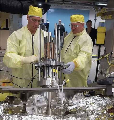
Integrating the heat pipe to both the reactor core and power conversion system required new mechanical and thermal bonding technologies in order for the system to operate efficiently over the lifetime of the system. Several integration designs were tested early in the Kilopower Project to determine the best method for attaching the heat pipes to the core. Ultimately, the interference ring design proved to be superior in both the mechanical and thermal performance categories. This design incorporated six interference rings that had to be heated to around 800°C in order to fit over the heat pipes and core. Once in place, the ring heaters were turned off, allowing the rings to cool until the correct interference fit and compression force were obtained. Special tooling and processes were developed to integrate the core with the heat pipes during the last stages of the reactor assembly that could streamline assembly, test, and launch operations at the launch site in the coming years. Assembly of the heat pipes to core can be seen in . The temperature drop between the core metal temperature and the sodium vapor temperature was less than 10°C throughout the test, showing how well the integration method worked.
Fig. 4. Installation of interference rings to clamp the eight heat pipes to the highly enriched uranium fuel.
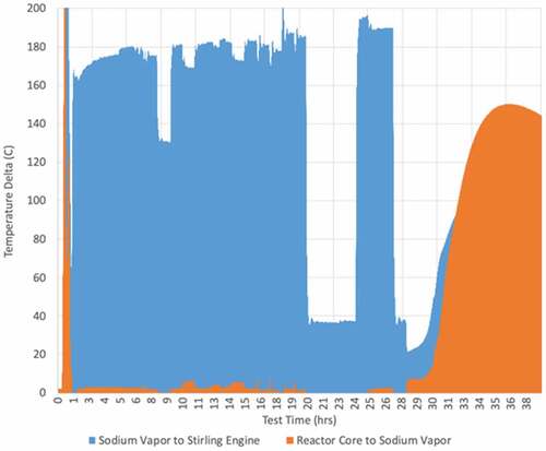
At the top end of the heat pipes, the Stirling convertors and simulators were coupled using a bolted split-clamp design. This design was used to allow easy installation of the convertors without any modification to the hot-end heat acceptor region so that the convertors could be used again in their original configuration. Ultimately, this modular bolted design was convenient for assembly but created the largest amount of thermal losses in the system with a temperature drop of up to 190°C. illustrates the temperature drops between the core and heat pipe vapor and the Stirling hot-end temperature. Future designs involving the correctly sized convertors will incorporate a better thermal coupling between the heat pipe and convertor using brazed or welded interfaces.
Fig. 5. Temperature deltas between the reactor core, the sodium vapor inside the heat pipe, and the hot end of the Stirling convertor.
I.A.1. Heat Pipe Processing and Performance
Each heat pipe went through a set of process and qualification steps before being assembled into the KRUSTY power system. After the heat pipes were fabricated and leak checked, the sodium was loaded into the pipe and the unit was processed using several techniques for degasification, passivation, and thermal performance. These tests were completed in air to allow for easier examination and processing throughout the break-in procedures. Thermal performance testing was completed using the Stirling thermal simulators to measure the thermal throughput out the condenser using a mass flow meter and the inlet and outlet temperatures of the nitrogen gas. This qualification testing verified each heat pipe’s performance before being selected for final assembly of the power system.
After qualification tests were complete on the single heat pipes, the system was assembled with the heat pipes, Stirling convertors, and thermal simulators in an array and structure that followed the conceptual design of the flight system. The system was coupled to stainless steel and depleted uranium cores through several electrically heated tests at National Aeronautics and Space Administration (NASA) to verify nonnuclear system-level performance. The electrical demonstrations allowed several opportunities for the system to be fully verified before shipping the assembly to the Nevada National Security Site (NNSS) for KRUSTY nuclear testing. Once at the Device Assembly Facility at the NNSS, the reactor assembly underwent several more tests including a full-power, electrically heated test as a final system checkout before operating the reactor.
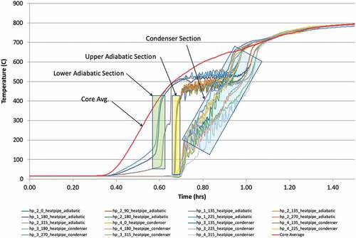
Initially, the heat pipes were required to start up from room temperature to 800°C in the first 90 min of the nuclear test. During this time period the sodium experiences multiple phase changes with varying levels of thermal capacity throughout the temperature range. All the heat pipes operated nominally as they did during the electrically heated tests. The startup transient is shown in , showing the sodium removing heat from the reactor core and transporting it to the adiabatic and condenser sections of the assemblies via two-phase flow. The thermocouples located in the adiabatic section just above the reactor core show the conduction of heat from the core through the heat pipe tube between 0.4 and 0.6 h. At near 0.6 h the core has passed 400°C and the sodium vapor starts to travel up the heat pipe, as can be seen by the steep slope of the thermocouples nearest the core in the lower adiabatic section. Soon to follow are the thermocouples located further up the heat pipe in the upper adiabatic section at around 0.67 h. The heated vapor reaches the condenser section shortly after at 0.70 h and begins to heat the condenser and the attached Stirling convertors and simulators. The slope of the lines associated with the condenser and convertor heating gradually increases as more thermal power is developed in the heat pipe as the vapor starts to carry more energy with the rising core temperature. Eventually, the system approaches steady state at near 1.5 h and all thermocouples associated with the core and heat pipes are very closely matched.
Fig. 6. Startup transient of the reactor core and several heat pipes showing the sodium removing heat from the reactor core and transporting it to the adiabatic and condenser sections of the heat pipes via two-phase flow.
The KRUSTY heat pipes had to be well-coupled to both the core and power conversion system to prevent delays that could influence the thermal communication between the core and power conversion system. There was approximately 1.0 m between the core and power conversion system that the supply vapor and return fluid had to travel to complete the communication loop. This response time between the core and the heat pipe vapor is shown in and . shows the response time between the core and heat pipe vapor during a reactivity insertion that took place at 18 h to raise the temperature of the core by moving the platen and radial reflectors up. The response time between the reactivity insertion, the core temperature, and the heat pipe vapor temperatures is indistinguishable in the graph. This provides valuable information on how well the heat pipe vapor responds to changes in the core temperature and is able to transfer the heat very quickly to the condenser and Stirling convertor.
Fig. 7. Thermal response time between core and heat pipes during reactivity insertion by raising the platen 1.5 mm.
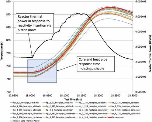
Fig. 8. Response time of convertor shutoff to rising temperatures of the core and sodium heat pipes.
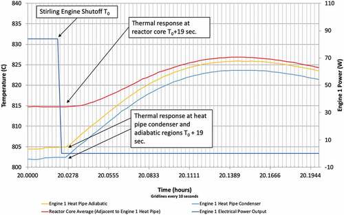
shows the opposite scenario were the Stirling convertors are turned off and the response time is determined. In this scenario the heat pipe adiabatic and condenser thermocouples are measuring vapor temperatures so the response time will include the fluid return time plus the vapor supply time. Almost all of the time is related to the thermal gradient moving from the internal heat acceptor of the convertor, through the pressure vessel, heat collector, interface material, and heat pipe condenser, and into the sodium fluid. The thermal resistance of this geometry and its associated interfaces are shown in and are the main contributor to the 19 s between the Stirling converter and heat pipe vapor. This is still insignificant to the overall system dynamics as the reactor’s temperature feedback wavelength is on the order of 1200 s in the coolant-loss scenario. Regardless, the core and heat pipe vapor temperatures are in phase with each other after the initial thermal lag between the convertor and core.
I.B. Stirling Convertors and Balancers
The two Stirling convertors used in the KRUSTY test, each composed of an engine and linear alternator, were made by Sunpower Inc. in 2010 as engineering units for the Advanced Stirling Radioisotope Generator (ASRG) project.Citation4–Citation6 The units, named Advanced Stirling Convertor E2-7 and E2-8, were originally intended for durability testing and completed several centrifuge and vibration tests during the 2010 to 2012 timeframe. In November 2012 the units were upgraded to include additional features that were necessary to improve manufacturability for the flight project. Originally built for use in a radioisotope generator, the two convertors were designed to be assembled into the generator housing in a coaxial arrangement with the alternator housing mounted back to back through a spool adapter. The hot ends of the convertor, located on opposite sides of the generator, incorporated a thermal heat collector that surrounded the pressure vessel at the acceptor region and transitioned to a flat interface to mate to the general purpose heat source. At the cold end, the convertor rejects its waste heat to the environment through a heat exchanger, referred to as the cold-side adapter flange (CSAF), positioned near the transition area where the convertor heater head meets the alternator housing. The CSAF is a mounting interface between the convertor and generator housing to thermally couple the convertor to the radiator surface of the housing. shows the original configuration of the convertors in the ASRG. In 2013, the ASRG flight project was canceled and several of the assets, including convertors E2-7 and E2-8, were no longer needed for future testing.
Fig. 9. Original design and depiction of the Stirling convertors developed for the ASRG project.
In 2015, the convertors were repurposed to undergo testing as part of the new nuclear fission project named Kilopower. The Kilopower generator concepts included system architectures that utilized several smaller Stirling convertors and heat pipes in an array to provide additional layers of redundancy and power scaling. In order to fit the convertors into a tight vertical array, the CSAFs were cut down to a smaller diameter and fitted with gas coolers for the tests. The heat-collector interface was not modified for the Kilopower tests and was directly bolted to the flat interface of the heat pipe condenser. The convertor array architecture also required a balancer to be used with each convertor in order to cancel out the inertia forces from the piston and displacer during operation. This was the first time that a single Stirling convertor was configured with a heat pipe and balancer and required a respectful amount of testing to characterize control and performance.
The balancer work was contracted to Sunpower Inc. to develop an active balancer and controller that would operate both the convertor and balancer together. Each controller and its associated convertor and balancer combination could achieve start, stop, and hold commands at any point throughout the test operations. The balancer used an accelerometer mounted on the top of the unit as the feedback mechanism for its control loop to achieve the correct frequency and piston amplitude for precise force cancellation. A software interface through the data collection system was used to send and receive commands from the controller, which was housed in the test rack outside the test cell area. The thermal input power and electrical output power of the convertor was controlled by changing the piston amplitude throughout the test. The maximum piston amplitude achievable without hitting hard limits was around 4.6 mm at 100 Hz.
I.B.1. Stirling Convertor Performance
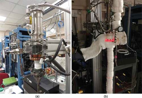
Operation of an eight-string array of single Stirling convertors with balancers in the configuration used for the KRUSTY test is a new idea that promotes increased turndown ratios (system electrical maximum capacity/minimum achievable electrical capacity) and overall system redundancy by allowing convertors and balancers to be controlled independently for on, off, and variable power operations. This architecture, when combined with a self-regulating reactor, has the advantage of conserving its fuel when power demand from the system is less during mission operations. Component testing was completed in several steps to ensure each string of the assembly was verified. The convertors were initially placed on test using an electrical heater at the hot end to test the functionality of the controller, balancer, and convertor. After successfully completing the convertor electrical testing, they were attached to the heat pipes and additional testing was performed to verify the operation of each completed string of the power system. shows the modified assembly and operational testing of one string of the power conversion and heat transport system including heat pipe, Stirling convertor, balancer, and controller.
Fig. 10. (a) Modified Sunpower E2 convertor combined with balancer (top) and heat pipe (bottom). (b) Operational testing of single-string power conversion and heat transport system using heat pipe, Stirling convertor, balancer, and controller.
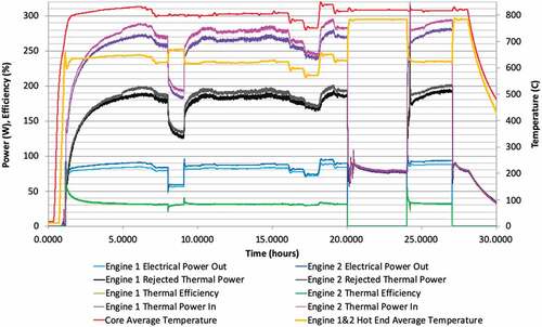
During the 28-h test, the Stirling convertors and balancers performed several operational procedures including start, stop, restart, and amplitude changes. shows the entire 28-h test data with temperatures, thermal and electrical power, and their associated efficiency. As with the earlier discussion on thermal resistances, the temperature drop of roughly 200°C between the heat pipe condenser and Stirling hot end could be improved with a new integrated design. Even with the lower hot-end temperature, the two convertors produced over 180 W of total electrical power, which is higher than their rated output. The rest of the data provide information on the thermal energy being input to the convertor through the hot end, the thermal output that is rejected through the cold-side gas cooler, and the converted electrical output coming out of the alternator. Together, these parameters balance the overall energy going into and out of the Stirling converters, and the thermal efficiency can be determined. The thermal efficiency is the percentage of the input thermal power that is converted into electrical power.
Fig. 11. Energy balance and efficiency of Stirling converters showing key data during 28-h nuclear test.
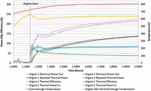
is a zoomed-in graph of the Stirling convertor startup. The convertor was started when the hot end reached approximately 650°C at around 50% of the total piston amplitude and ramped up as the temperature of the convertor recovered and the reactor core came up to its set-point temperature. The increases in piston amplitude can be noticed in the sharp increases in electrical power data. During mission operations, it is anticipated that the flight controller and Stirling convertor controller will automatically start the convertors at the desired temperature. The convertors may also be able to self-start once enough thermal energy has been collected at the hot end. Continued operation of the convertor and power conditioning will take place within the Stirling controller and power management system.
Fig. 12. Stirling convertors started when hot end reached 700°C.
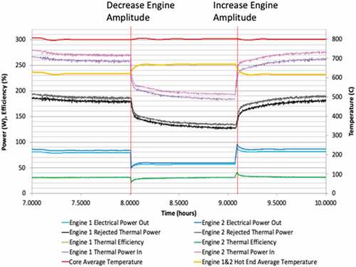
At 8 h into the test, the convertor amplitude was reduced by half to see how the reactor would load following the decreasing load (). As expected, the reactor core went through its damped oscillations and recovered to the set-point temperature. The convertor hot-end temperatures increased, the power output decreased due to decreased piston amplitude and thermal efficiency, and the core temperature stayed nearly constant. The nearly constant efficiency of 30% during the reduced power operation is important because not all power conversion systems can do this and it has advantages. The advantage could come into play during a mission if the power demand is reduced, allowing the converters to match the power by changing amplitude or turning some converters off. This in turn decreases the reactor power and its radiation signature, which increases the life of the reactor as well as other system components. Outer-planet missions may have years of transit time that require much less power. With the Kilopower reactors and Stirling technology, the reactor could be turned down to 1/16 the power in an eight-convertor array while the reactor continues to operate at 800°C. An even further reduction in power can be achieved if the control rod is set to allow a lower operating temperature down to 600°C. Below 600°C the heat pipe heat transport performance would be reduced to an unacceptable level.
Fig. 13. Stirling convertor piston amplitude turned down to see how core responds to decreased thermal load. Convertor hot-end temperatures increase, power output decreases due to decreased amplitude, and thermal efficiency and core temperature stay nearly constant.
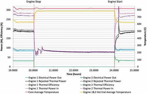
At approximately 20 h, the convertors and simulators were completely turned off. In the stalled convertors behave as expected with the hot-end temperatures rising to just below 800°C with only the thermal losses present. The thermal losses are shown as the rejected thermal power curves leaving the rejection system through the gas heat exchanger. These losses conducted and radiated from the convertor hot end up to the modified cold-side adapter flange and added up to approximately 80 W of thermal power. These losses are different when the convertor is running as gas is being cycled, changing the internal and external temperatures of the hot-end assembly. At approximately 24 h, the convertors were restarted and continued to operate as before.
Fig. 14. Stirling convertor stops and restarts at the 20-h mark.
After 28 h of operation the reactor was shut down and the system gradually cooled down. The Stirling convertors could continue to operate with the reactor off to actively cool the core faster if desired, but this was not included in the test operations.
II. CONCLUSIONS AND REMARKS
The KRUSTY nuclear test was executed within a short period of time and a modest budget to determine if the Kilopower reactor design could adequately provide electrical power for upcoming NASA missions over a wide range of operating conditions. Although the test could not fully include all the environmental conditions of a mission due to a mission not being defined, the neutronic and system behavior was predicted and verified throughout the test. The main objectives were successfully completed by operating the reactor at steady state at the designed power levels and temperatures, operating the system over several simulated mission scenarios to verify that the reactor can handle extreme variations at the power system, and collecting valuable data that allow better prediction and design of future reactors. The data and lessons learned provide a significant amount of risk reduction and credibility toward the Kilopower reactor design as it moves toward a flight system. As the first Kilopower mission approaches, several more tests will be completed to qualify the system and finalize the design.
References
- D. I. POSTON, M. A. GIBSON, and P. R. McCLURE, “Design of the KRUSTY Reactor,” Proc. Nuclear and Emerging Technologies for Space, American Nuclear Society, LaGrange Park, Illinois (2018).
- M. A. GIBSON et al., “Kilopower Reactor Using Stirling TechnologY (KRUSTY) Nuclear Ground Test Results and Lessons Learned,” NASA/TM-2018-219941, National Aeronautics and Space Administration (2018).
- M. A. GIBSON et al., “NASA’s Kilopower Reactor Development and the Path to Higher Power Missions,” NASA/TM-2017-219467, National Aeronautics and Space Administration (2017).
- W. A. WONG et al., “Advanced Stirling Convertor (ASC) Technology Maturation,” AIAA 2015-3806, American Institute of Aeronautics and Astronautics (2015).
- S. D. WILSON and W. A. WONG, “NASA Glenn Research Center Support of the Advanced Stirling Radioisotope Generator Project,” NASA/TM-2015-218462, Advanced Stirling Convertor, National Aeronautics and Space Administration (2015).
- S. D. WILSON, J. F. METSCHER, and N. A. SCHIFER, “Active Vibration Reduction of the Advanced Stirling Convertor,” Proc. 14th Int. Energy Conversion Eng. Conf., Salt lake City, Utah, American Institute of Aeronautics and Astronautics (2016).