
 ?Mathematical formulae have been encoded as MathML and are displayed in this HTML version using MathJax in order to improve their display. Uncheck the box to turn MathJax off. This feature requires Javascript. Click on a formula to zoom.
Abstract
The centerpiece of the Kilopower Project, i.e., the Kilowatt Reactor Using Stirling TechnologY (KRUSTY) test, consists of the development and testing of a ground technology demonstration of a small fission power system based on a 1-kW(electric) space science power requirement. The KRUSTY test was authorized by the U.S. Department of Energy’s (DOE’s) National Nuclear Security Administration Nevada Field Office. Authorization was obtained by adding an amendment to the existing regulatory documents for the National Criticality Experiments Research Center to cover the KRUSTY experiment. This amendment was reviewed and approved by the DOE. The most important safety question for the experiment was the addition of over 2 $ of excess reactivity to the reactor system. This amount of excess reactivity meant that the analyst could postulate accidents where the reactor went prompt critical, leading to physical shock or melting of the fuel. This paper analyzes these accidents using computer calculations and examines the controls used to mitigate them. The estimation of the impacts both on accident progression and consequences of reactivity insertion events was a significant part of obtaining approval for the KRUSTY experiment. The regulatory approval of KRUSTY was one of the first to be obtained for a completely new reactor concept in many decades.
I. INTRODUCTION
The Kilowatt Reactor Using Stirling TechnologY or KRUSTY experiment was designed to evaluate the performance of a 1-kW(electric) space reactor concept. The experiment was performed by Los Alamos National Laboratory (LANL) with support from the National Aeronautics and Space Administration’s (NASA’s) Glenn Research Center and Mission Support and Test Services at the National Criticality Experiments Research Center (NCERC). The NCERC is housed in the Device Assembly Facility at the Nevada National Security Site. The site is regulated by the U.S. Department of Energy’s (DOE’s) National Nuclear Security Administration (NNSA), which maintains a field office in Las Vegas, Nevada. The current regulatory limit for experiments at NCERC is an excess reactivity of 0.80 $. Experiments below 1 $ cannot enter the prompt critical range and thus cannot see an exceedingly fast exponential increase in reactor power under off-normal conditions. The KRUSTY experiment required ~2 $ of excess reactivity to overcome the natural reactivity feedback and reach the desired operating temperature of 800ºC. This required an amendment to existing regulatory documents and approval by the DOE/NNSA Nevada Field Office.
II. KRUSTY EXPERIMENT OVERVIEW
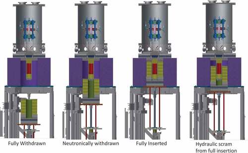
The KRUSTY experiment consisted of a 32-kg highly enriched uranium alloy (8% molybdenum) core, surrounded by a beryllium oxide reflector, with eight heat pipes that removed heat from the core and delivered that heat to Stirling engines that produced electricity. The remaining heat was carried away by nitrogen. The core, heat pipes, and Stirling engines were in a vacuum environment. The system achieved criticality by lifting the reflector into place around the reactor core using the safety-certified lift mechanism of the Comet critical assembly machine. This configuration is shown in .
Fig. 1. KRUSTY experiment on the Comet platform at different stages of reactivity (reactor core in red, beryllium oxide reflector in yellow, and Stirling engines in blue).
III. EXPERIMENT HAZARDS AND POTENTIAL ACCIDENTS
Most of the hazards associated with the KRUSTY experiment are common to many critical assembly operations at NCERC involving nuclear materials (e.g., dispersal of radioactive material by mechanical and thermal insults). These hazards were evaluated in the safety analysis documents and did not require further analysis but are discussed here for completeness.
A total of eight 1000-L liquid nitrogen dewars were used in the experiment to supply nitrogen gas to cool the Stirling engines. The large amount of cryogenic nitrogen represents a significant asphyxiation hazard in the event of a leak into the room. This hazard was controlled (at least in part) by the use of oxygen monitors in the room to alert workers in the event of a nitrogen leak in accordance with Occupational Safety and Health Administration requirements.
Other unique KRUSTY experiment hazards, such as a small amount of sodium (15 cm3) in the heat pipes, were evaluated and found to be insignificant. The most significant hazard unique to the KRUSTY experiment is the large amount of excess reactivity required.
Reactivity ρ is an indication of the relative departure of the effective multiplication factor from unity or (keff −1)/keff. Excess reactivity (sometimes referred to as the maximum excess reactivity) is simply the largest reactivity achievable when the configuration is fully assembled. Reactivity is typically indicated in units of dollars and cents, where the dollar unit of reactivity is defined as the reactivity ρ divided by the effective fraction of delayed neutrons βeff, where βeff is 0.0069 for the KRUSTY experiment. The Monte Carlo N-Particle Transport (MCNP) computer codeCitation1 was used to calculate βeff for KRUSTY.
An excess reactivity up to 2.20 $ was analyzed as the potential loading onto Comet for the high-temperature operations of the KRUSTY experiment. This large amount of excess reactivity has the potential to cause significant heating of the core, possibly higher than the melting point of the uranium-molybdenum core. The potential reactivity accidents that could hypothetically raise the temperature of the core above its melting point are discussed below.
IV. THE NEED FOR 2.2 $IN EXCESS REACTIVITY
The large amount of excess reactivity is needed to overcome the negative temperature coefficient as the reactor heats up (the negative temperature coefficient is almost entirely from thermal expansion of the fuel). The final operating temperature of 800ºC was initially estimated to require approximately 1.70 $ of reactivity to stay at a keff of 1.0. Another 50 ¢ of reactivity was added as margin to bring the total amount of reactivity to 2.20 $. This reactivity came from the addition of BeO reflector material onto the platen that was raised to make the reactor critical. More BeO would provide less gap between the top reflector and the reflector on the platen, thus increasing reactivity.
V. POTENTIAL ACCIDENTS
Based on potential abnormal loading and insertion conditions, three potential accident scenarios were postulated and evaluated in the Process Hazard Analysis section of the safety analysisCitation2:
1. First scenario—an uncontrolled prompt (step) excess reactivity insertion: A prompt or step insertion is postulated to be set up by raising the platen with no neutron source, i.e., a sourceless start-up. Spurious neutrons are assumed to cause a power transient when the platen is raised, inserting an excess reactivity greater than 1.40 $. The scenario assumes that no spurious neutrons are available prior to full reactivity insertion. (The 1.40 $ insertion is based on historic precedent and is fully explained later).
2. Second scenario—an uninterruptible full excess reactivity insertion rate: A reflector configuration with a significant amount of excess reactivity is postulated to be inserted too quickly by raising the platen at too high a speed (Comet has a programmable rate limit).
3. Third scenario—an overloaded uninterruptible full excess reactivity insertion: Comet is loaded with an amount of excess reactivity well above the 2.20 $ needed for the experiment.
The hazards analysis estimated these accidents to have a probability of between 10−2/year and 10−4/year, and they are considered design-basis accidents.
The analyses of these unlikely conditions indicate that the potential for fuel melt exists for all scenarios based on the peak fuel temperature exceeding the melting point for uranium metal (about 1130ºC). The uranium-molybdenum fuel matrix would melt at a slightly higher temperature. It is also important to note that the Process Hazards Analysis conservatively assumes a complete melting of the core as a result of these accident scenarios. The results of the analyses indicate the peak fuel temperature will exceed the melting point of uranium for at most a few minutes. While this temperature transient could cause some fuel damage, it will not result in complete melting of the entire core, as is assumed in the analysis to estimate bounding consequences.
The analysis assumes that operators take no action to prevent the postulated accident scenarios. Operators monitor several parameters during the experiment and are likely to notice an abnormal condition based on their experience in operating Comet and training for the KRUSTY experiment. Although the bounding outcomes would have likely been prevented by operator intervention, such as manually scramming Comet, the analysis assumes no operator action in order to examine the potential worst-case accidents.
VI. METHODOLOGY FOR ANALYZING ACCIDENTS
Reactor dynamic calculations were performed using a suite of codes, including some space reactor design codes developed by LANL. The tools include the following LANL codes: MCNP, Fission Reactor Integrated Nuclear Kinetics (FRINK) (CitationRef. 3), and MONTEBURNS (CitationRef. 4) and the following Oak Ridge National Laboratory code: Oak Ridge code Isotope GENeration (ORIGEN) (CitationRef. 5). Reactor dynamics are analyzed by FRINK through the use of a point-kinetics model with reactivity temperature coefficients (RTCs). The RTCs are calculated with MCNP. After FRINK analyzes the transient, the source term is calculated with MONTEBURNS/ORIGEN based upon the number of fissions.
VII. MCNP CODE
The MCNP code is the LANL Monte Carlo code for radiation transport. MCNP is widely used in studies of advanced reactor concepts, either directly as a mainline design tool or indirectly as part of the verification/validation process. MCNP is routinely used to calculate the multiplication factor keff and detailed distributions of power and reaction rates. MCNP provides highly accurate results, using continuous-energy physics, ENDF7.0 and ENDF7.1 nuclear data, and explicit three-dimensional (3-D) constructive solid geometry. The quality assurance (QA) for MCNP6 is outstanding and is a result of the DOE-wide use of the code in criticality safety analysis.
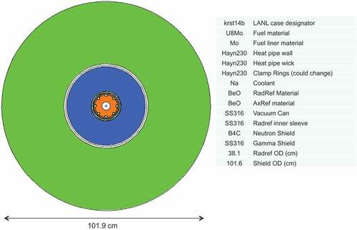
The model for the KRUSTY experiment is based upon the design from LANL and NASA. The configuration of the reactor core, reflector, and shielding is shown in . The MCNP model of the experiment is shown in and .
Fig. 2. Side view of KRUSTY core, reflector, and shielding (reactor core in red, beryllium oxide reflector in yellow, and shielding in blue and gray).
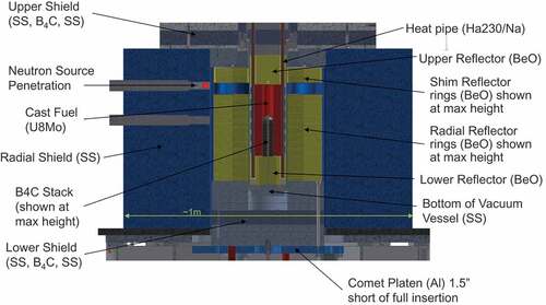
Fig. 3. MCNP6 model side view.
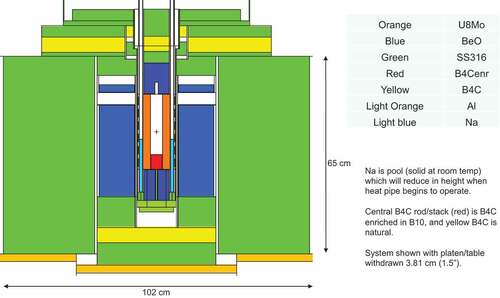
Fig. 4. MCNP6 model top view of core.
VIII. REACTIVITY TEMPERATURE COEFFICIENTS
The term “reactor component” refers to system subassemblies such as fuel, radial reflector, bottom reflector, steel shield, etc. Each reactor component can have a different average temperature. The average temperature of the component was used to evaluate the reactivity of the component. The temperature of the component is derived from the heat transfer equations solved by FRINK.
Reactivity coefficients are used to approximate the change in reactivity as a function of temperature for each reactor component. The power of the reactor is calculated from the amount of reactivity ρ and average neutron lifetime. Because there is a range of neutron lifetimes, average neutron lifetimes are approximated by binning neutron lifetimes into groups of similar values. A typical point-kinetics model (a simple nondimensional solution to the power equations for a reactor system) uses six bin sizes to approximate the average neutron lifetimes that range over several orders of magnitude.
The power of the reactor, as approximated by the point-kinetics model, can then be used in FRINK to evaluate the change of temperature of the system during a transient event, such as an accidental insertion of reactivity. The power of the reactor is calculated by EquationEq. (1)(1)
(1) for each neutron lifetime bin:
where
| Pfis = | = | fission power in the reactor |
| Qfis = | = | mega-electron-volts per fission deposited in system |
| ρ = | = | total reactivity (i.e., keff) for this equation |
| Ʌ = | = | prompt neutron lifetime |
| ν = | = | neutrons per fission |
| n = | = | neutron population. |
The reactivity coefficients for KRUSTY by major component are presented in .
TABLE I Reactivity Coefficients by Component
IX. FRINK TRANSIENT ACCIDENT CALCULATIONS
The reactivity transients were modeled and analyzed using FRINK, which is a FORTRAN-based point-kinetics neutronics model coupled to a 3-D finite difference heat transfer model. Point kinetics is well suited for KRUSTY because it is a very compact, fast spectrum reactor; i.e., the thermal solution will not greatly impact the spatial flux/power profile. The combined set of differential equations, approximated by the Crank-Nicolson method, is reduced with a matrix solver. The purpose of the code is to estimate the system response to various transients including reactor start-up, power conversion start-up, shutdown, and various operational and potentially safety-related events.
The neutron kinetics solution is based on the RTCs presented in Sec.VIII, and reactivity is based on the position of the Comet platen (which holds the BeO radial reflector). MCNP calculations provide the worth of the platen from the fully withdrawn to fully closed positions. The time-dependent movements of the platen can be input directly or calculated via an operator simulator.
The thermal solution is based on the power calculated by the point kinetics, derived from the neutron population based on inputs for mega-electron-volts per fission and neutrons per fission. The calculated power is distributed among all of the core components according to their power deposition fractions, which are also calculated by MCNP. The fuel is divided into 12 radial and 5 axial nodes. Within the fuel, the 3-D power peaking profile is input from MCNP so that the power is properly distributed among the fuel axial and radial nodes (azimuthal power peaking effects are minor and are ignored). Decay power is tracked and binned according to a profile calculated with MONTEBURNS and ORIGEN. Heat is transferred among the nodes/components via conduction and radiation (convection is simulated in the heat pipes, at the Stirling interface, and with a small amount of natural convection to the ambient air). Each reactor component can be divided into a variable number of radial, axial, and azimuthal nodes according to code input. Material properties (k, Cp, ρ, CTE, ε, υ) are recalculated at every iteration as a function of temperature. Gap conductances are input for all components that are in physical contact. Radiation heat transfer is calculated for all components that view each other and are not in physical contact (regardless of whether the gap is air or vacuum). Conduction across air gaps is calculated for adjacent components that are outside the vacuum chamber but are not in contact.
FRINK contains a simple heat pipe model that bounds heat transfer according to the sonic, viscous, and flooding limits. The evaporator is conductively coupled to the fuel and clamps by a specified gap conductance, which is determined by the electrically heated testing. The evaporator is also radiatively coupled to the clamps and multilayer insulation.
The FRINK model ends at the hot end of the Stirlings, where the gas removes the heat. The power removal by the Stirlings is based on correlations developed by NASA based on the engine stroke, the acceptor temperature, and the heat rejection temperature.
FRINK is an internally developed user code and does not have the code validation or verification QA necessary to be used for safety analysis. In fact, there are no codes in existence that are qualified in their current state to validate KRUSTY transients, which is why the experiment has been designed to verify safety without relying directly on transient analyses. The regulator required a compensatory measure because FRINK did not have the appropriate QA. The compensatory measure was to use FRINK to calculate the reactor core temperature for a low-temperature transient that inserted 0.60 $ of reactivity prior to performing the high-temperature experiment. This compensatory measure will be discussed in Sec. X.C.
Three primary reactivity insertion accidents were identified in the Hazards Analysis. These are
a step insertion of reactivity leading to core melt
a rate insertion of reactivity leading to core melt
an overinsertion of reactivity leading to core melt.
The three accidents are examined in Secs. IX.A, IX.B, and IX.C.
IX.A. Step Insertion Accidents
Prompt reactivity insertions were evaluated for reactivities of 1.00 $ to 1.40 $. A step insertion is defined at the point when a chain reaction is sustained (e.g., a 1 $ step insertion means that a sustained chain reaction or sensible heating/feedback does not begin until the system reaches 1 $ of reactivity). It is the same as if the reactivity was introduced instantaneously (e.g., platen was inserted infinitely fast). In a real physical system, reactivity cannot be inserted in a perfect step (infinitely fast), meaning it takes time for a system to move from subcritical through delayed critical to prompt supercritical. However, a step insertion can occur if a chain fails to be established in the time it takes to insert the reactivity. This could occur if there was no neutron source or no neutron from the environment to begin the chain reaction. A step insertion is also a reasonable approximation if the reactivity insertion is fast compared to the heat transfer rate and/or the effects of delayed precursors entering the equation.
The probability of a step insertion depends on several factors including (1) how long it takes to insert the reactivity, (2) the rate at which “stray” neutrons interact with the fuel (i.e., the neutron source), and (3) the level of supercriticality. The factors when taken together mean that the probability of a step insertion is very unlikely. A step insertion of 1.40 $ causes approximately 1017 fissions in a fast and highly reflected system like KRUSTY. This number of fissions is correlated to the highest step insertion reactivity accidents ever recorded for this type of reactor assembly. McLaughlin et al.Citation6 present one such accident that occurred in Livermore, California, in 1963 involving a 47-kg uranium cylinder with Be reflector at 3.7 × 10¹⁷ fissions. Based upon the data available from these extreme accident conditions and knowing that preinitiation will certainly affect these transients under real (i.e., nonstep-insertion) conditions, step insertions beyond 1.40 $ are considered incredible for this experiment.
Since FRINK does not model the transition between the solid metal and melting phase of the U-Mo core, it is assumed that the core melts at about 1130ºC. Keep in mind that an instantaneous large (>1.00 $) step insertion of reactivity is essentially impossible in a reactor that is not designed to be pulsed because for a highly enriched uranium assembly, the presence of a neutron source or the presence of spontaneous neutrons is likely to be noticeable very early (for example, the reactor operators are monitoring neutron levels) and the platen speed is limited by design and control.
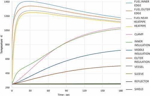
The calculational results for a step insertion of 1.40 $ are shown in and . shows power as a function of time and reactivity. shows the corresponding temperature in the fuel and other reactor components.
Fig. 5. Power and reactivity for a 1.40 $ step insertion.
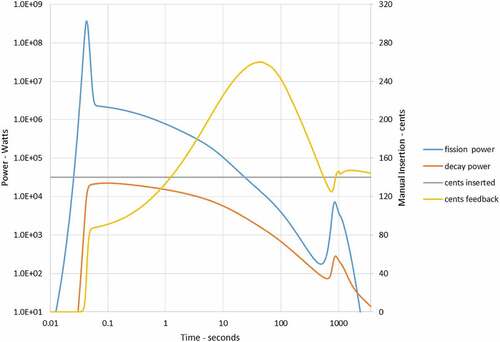
Fig. 6. Temperature of reactor components for a 1.40 $ step insertion.
shows that an uncontrolled instantaneous prompt reactivity insertion of 1.40 $ or more, when loaded onto Comet, could result in temperatures that exceed the onset melting temperature of uranium-molybdenum alloy (partial peak axial midplane melting). Thus, it is assumed that a large step prompt reactivity insertion is likely to result in significant fuel melt.
IX.B. Reactivity Rate Insertion Accidents
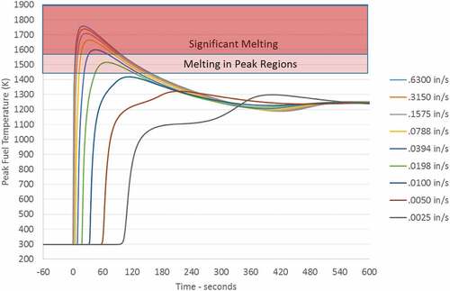
Analyses evaluated the impact of the platen (unimpeded to full closure) velocity for an excess reactivity insertion of 2.20 $. These analyses evaluated the platen speed from 0.064 cm/s (0.025 in./s) to the maximum platen design speed of 1.6 cm/s (0.63 in./s).
presents the results of the analyses for the 2.20 $ excess reactivity insertion. From the analyses, it is seen that when 2.20 $ is inserted at speeds slightly above 0.025 cm/s (0.010 in./s), at the point delayed critical is reached, incipient fuel melt could occur. Thus, significant melting of the fuel is expected if the platen is inserted at the maximum design platen speed [namely, 1.6 cm/s (0.63 in./s)] or at speeds greater than about 0.089 cm/s (0.035 in./s).
Fig. 7. Rate insertion accident for a 2.20 $ of excess reactivity; fuel temperature for various platen insertion speeds.
Uninterrupted full insertion represents a worst-case scenario and is deemed incredible. For the KRUSTY experiment, the Comet machine speed is limited to 0.02 cm/s (0.008 in./s) when first critical is approached. At these very slow platen speeds, the potential for operator response is far greater due to the relatively large time available (minutes).
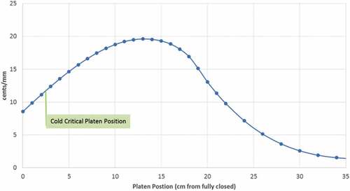
One positive design feature of KRUSTY is that the worth of the platen movement gets smaller as the system approaches a critical condition as indicated in . From , one can see that the highest differential worth region is when the platen is about 12.5 cm from fully closed.
Fig. 8. Calculated KRUSTY platen movement worth for cold nominal case.
The speed control is programmed to decrease the insertion rates as the platen approaches full closure as previously described. In other words, the platen speed is programmed to go from 1.02 cm/s (0.400 in./s) up to 12.7 cm (5 in.) of closure, 0.02 cm/s (0.008 in./s) from 2.54 cm (1 in.) to 1.90 cm (0.75 in.) of closure, 0.02 cm/s (0.004 in./s) from 1.90 cm (0.75 in.) to 1.27 cm (0.5 in.) of closure, and 0.005 cm/s (0.002 in./s) from 1.27 cm (0.5 in.) to 0.0 cm of closure.
In conclusion, incipient fuel melt could occur for rate insertion accidents if the platen speed is greater than 0.025 cm/s (0.01 in./s). However, fuel melt is unlikely due to the programmed platen rates at the level of first critical [about 0.02 cm/s (0.008 in./s) from 2.54 cm (1 in.) to 1.27 cm (0.75 in.) from closure], and 0.005 cm/s (0.002 in./s) at the level of warm critical [1.27 cm (0.5 in.) from closure to full closure]. These rates are a factor of 5 below the rates estimated to cause melting of the core. These very low programmed platen speeds also provide the operators time to respond to an unexpected condition due to the relatively large periods (order of minutes), especially at the beginning of platen movement and up to within 1.27 cm (0.5 in.) of full closure.
IX.C. Overinsertion of Reactivity Accidents
An analysis of the maximum excess reactivity insertion that will result in fuel melt irrespective of platen speed was also performed. This analysis was based on a misloading of the platen with excess reflector, for a total excess reactivity insertion of 2.75 $.
This scenario corresponds to an increase of slightly 1.00 $ over the actual reactivity needed to achieve the desired fuel temperature of 800ºC. This additional 1.00 $ or so of excess reactivity (margin) can take the fuel from about 800ºC to about 1100ºC (approximately the melting temperature of the fuel). This result means that at these overload conditions, any insertion rates will likely result in fuel melt.
For these three postulated uncontrolled scenarios to occur, several simultaneous and often independent events must happen. It is important to note that to support the experiment needs for KRUSTY with respect to determining the neutron multiplication of a source, the stack heights needed to achieve a cold critical, platen insertion rate settings, and the excess reactivity needed to achieve the KRUSTY operating temperature conditions; a set of discrete nuclear operations and evaluations was performed as part of the authorization for continued operations; i.e., there were hold points during transition between low-temperature (<400ºC) critical operations and high-temperature (~800ºC) operations. That is, during the low-temperature critical operations (well before the platen is fully loaded), the reactor was operated up to the current Comet authorization basis limit (i.e., 80 ¢ excess reactivity) to evaluate the adequacy of the reactivity calculations performed to support the current operations and accident analysis.
The completion of the low-temperature criticals and the evaluations served as a holdup point in the operations, as the results of the tests were compared to the pretest predictions made with FRINK to support the design and safety of KRUSTY operations.
X. INHALATION DOSE CALCULATIONS
To calculate the dose to the public and worker, the standard formulas for dose and accident source term [as presented in DOE-HNBK-1224 (CitationRef. 7)] are the following:
and
Combining EquationEqs. (2)(2)
(2) and Equation(3)
(3)
(3) provides
where
| MAR = | = | material at risk (curie inventory of radioactivity in the core) |
| ARF = | = | airborne release fraction |
| RF = | = | respirable fraction |
| DR = | = | damage ratio (assumed to be 1) |
| LPF = | = | leak path factor (assumed to be 1) |
| X/Q = | = | atmospheric dispersion factor (s/m3) |
| BR = | = | breathing rate (m3/s) |
| DCF = | = | dose conversion factor (rem/Ci) |
| Dose = | = | total effective dose equivalent (50 yr) (rem). |
Using EquationEq. (4)(4)
(4) , the dose for each individual isotope was calculated in a spreadsheet. The values are then summed to arrive at the total dose to the maximally exposed off-site individual and the 100-m dose to a hypothetical worker.
X.A. Dose Calculation Assumptions
The values assumed for basic parameter values in the dose calculations are shown in . These values are the same as the current regulatory document for the NCERC operations. Conservative assumptions are used for the release of fission products from a melted core. No credit is taken for the experimental vacuum chamber or the facility and its filtration system. This is an unmitigated (parking lot) scenario used by the DOE/NNSA to classify the level of safety systems.
TABLE II Assumed Values for Dose Calculations*
A discussion of the assumed parameters is needed to set context for the calculations. There is no adequate basis for ARF and RF for this calculation. The original NCERC safety analysis used a bounding value of 10−3 for burning uranium over the uranium release from heat fuel of 4 × 10⁻⁴ [both values from DOE-HDBK-3010 (CitationRef. 10)]. The largest value for uranium is the free fall of molten drops, which is the worst-case release from uranium excluding explosive dispersal and has a bounding Airborne Release Fraction X Respirable Fraction (ARFxRF) of 10−2. This value was chosen just to be conservative, not for realism.
Different release fractions would apply for the fission products. Tables 6 through 10 of DOE-HDBK-3010 provide ARFxRF for different chemical classes of fission products. It would be too time-consuming to determine the appropriate chemical class for each isotope and use the appropriate ARFxRF. An extremely conservative value ARFxRF of 5 × 10⁻¹ for noble gases for heated fuel was used. A value of 0.5 will be used for all fission products for conservatism and ease of implementation.
The dose conversion factors for the public come from International Commission on Radiation Protection (ICRP) publication ICRP-72 (CitationRef. 12). The assumption was made to use the fast absorption values for all isotopes. For the uranium, the fast absorption values are the largest and most conservative. This will not be the case for many of the fission product isotopes, but most of these do not contribute heavily to the overall dose. Choosing the fast values was a consistent way of adding a large number of dose conversion factors to the calculation. The basis for adding a dose conversion factor to the calculation was as follows: If the conversion factor had been calculated by ICRP and there was a corresponding isotope produced by the ORIGEN code, then the conversion factor was added. This meant that over 95% of the isotopes in ICRP-72 were included in the calculation. The same process was followed for ICRP-68 (CitationRef. 13) for workers. Here, the only difference was that the values for 5-μm particles were selected. This is near the mean of the distribution for inhaled uranium particles. Note that cloud shine from the fission products (usually known as immersion) was not included in the calculation. The time of plume passage would be short enough (minutes) that cloud shine would not give an appreciable increase to the dose to the worker or public.
In addition, no allowance is made for the decay of fission products during transport to the 100-m receptor or the site boundary. The 95-percentile atmospheric dispersion will typically occur at low wind speeds and stable atmospheric conditions. F stability and 1 m/s wind speeds are typical, but the conditions can realistically be bounded by D stability and 3.5 m/s for most locales. This means that transport time to the 100-m receptor is on the order of 30 s and to the public is on the order of 50 min. These decay times are conservatively not accounted for in the calculations.
The fission product inventory of the core was calculated for two cases using the ORIGIN code. For the first case the experiment was run for its intended time of 28 h, allowing the buildup of fission products, and then, an accident causes melting of the core. The second calculation assumed a double run time of 56 h and then core melting.
X.B. Dose Calculation Results
The dose to the public and the collocated worker for each case is presented in . The doses to the public are all in the millirem range or less and are far below the bounding dose calculated for a Comet reactivity excursion in the original NCERC safety analysis. This difference is primarily because the original analysis is based on melting a significant quantity of plutonium, which causes much larger doses than releases from uranium fuel, such as the KRUSTY core. The potential dose consequence for the worst-case KRUSTY experiment accident is “bounded” by the current dose consequence.
TABLE III Doses to Collocated Worker and Public
The worker dose at 100 m was not calculated in the original safety analysis. It is for information only and was not to be used to determine the safety designation of any system at this time. However, this calculation does show that the criterion in DOE-STD 3009-2014 (CitationRef. 14) of “100 rem at 100 m” is not challenged. This dose consequence is below a level of concern.
X.C. Controls Implemented as a Result of Analysis
Several controls were added to the technical safety requirements for operating the Comet platform for use by the KRUSTY experiment. These controls were only for this experiment and were derived from the safety analysis.
First, given the lack of appropriate QA for the FRINK computer code, a hold point was inserted into the operation procedures before high-temperature (~800ºC) operations were allowed to proceed. The hold point required us to predict the peak temperature at the core’s outer edge during a 60 ¢ reactivity insertion warm temperature critical experiment to be within 20% (plus or minus) of the actual measured temperature. We predicted a peak temperature of 446ºC; the actual was 447ºC. This test result is documented in work by Poston et al.Citation15
Second, the experiment required a sealed neutron source to be used to prevent a step insertion of reactivity.
Third, a rate limit was imposed on the Comet platen using the programmable speed controller to a level that was far below the speed where the core temperature could approach melting.
Finally, the total excess reactivity limit for the Comet machine was set at the measured reactivity defect to achieve 800ºC plus 50 ¢ in margin. The final reactivity loaded onto the machine was ~2.00 $, although 2.20 $ was analyzed.
XI. SUMMARY
The estimation of the impacts both on accident progression and consequences of reactivity insertion events was a significant part of obtaining approval for the KRUSTY experiment. The regulatory approval of KRUSTY was one of the first to be obtained for a completely new reactor concept in many decades. The process and results demonstrate that with appropriate planning and analysis, obtaining approval for new reactor configurations is a very achievable goal.
Acknowledgments
We would like to thank all members of the Kilopower team for their commitment to realizing the first demonstration of space fission power technology in over 50 years. We would also like to thank NASA’s Space Technology Mission Directorate and Game Changing Development Program, as well as the DOE/NNSA Nuclear Criticality Safety Program, for their sponsorship and vision in seeing the Kilopower technology through to the conclusion of its first groundbreaking step toward abundant, affordable power for space missions to the solar system’s most challenging and interesting locations.
References
- D. B. PELOWITZ, “MCNP6 User’s Manual,” LA-CP-11-1708, Los Alamos National Laboratory.
- “Kilopower Reactor Using Stirling TechnologY (KRUSTY) Experiment Amendment to the Device Assembly Facility Documented Safety Analysis Addendum for the National Criticality Experiments Research Center,” Mission Support and Test Services (June 22, 2017).
- D. I. POSTON et al., “FRINK—A Code to Evaluate Space Reactor Transients,” AIP Conf. Proc., 880, 449 (2007); https://doi.org/10.1063/1.2437485.
- D. I. POSTON and H. R. TRELLUE, “User’s Manual, Version 1.00 For Monteburns, Version 3.01,” LA-UR-98-2718, Los Alamos National Laboratory (June 1998).
- A. G. CROFF, “ORIGEN2: A Versatile Computer Code for Calculating the Nuclide Compositions and Characteristics of Nuclear Materials,” Nucl. Technol., 62, 3, 335 (1983); https://doi.org/10.13182/NT83-1.
- T. P. McLAUGHLIN et al., “A Review of Criticality Accidents, 2000 Revision,” LA-13638, Los Alamos National Laboratory (May 2000).
- “Hazard and Accident Analysis Handbook,” DOE-HDBK-1224, U.S. Department of Energy (Aug. 2018).
- “Device Assembly Facility Documented Safety Analysis Addendum for Criticality Experiments Facility Operations, Revision 1–Change Notice 3,” LLNL-MI-407120, Los Alamos National Laboratory, National Criticality Experiments Research Center (Dec. 2010).
- DOE-STD-1189-08, “Integration of Safety into the Design Process,” U.S. Department of Energy, Washington, D.C. (Mar. 2008).
- “Airborne Release Fractions/Rates and Respirable Fractions for Nonreactor Nuclear Facilities,” DOE-HDBK-3010, U.S. Department of Energy.
- DOE-STD-3009-94, “Preparation Guide for U.S. Department of Energy Nonreactor Nuclear Facility Documented Safety Analysis” (July 1994), Change Notice 3 (Mar. 2006), U.S. Department of Energy, Washington, D.C.
- “Age Dependent Doses to Members of the Public from Intake of Radionuclides: Part 5, Compilation of Ingestion and Inhalation Dose Coefficients,” ICRP Publication 72, International Commission on Radiation Protection, Ann. ICRP, 26, 1 (Sep. 1995).
- “Dose Coefficients for Intakes of Radionuclides by Workers,” ICRP Publication 68, International Commission on Radiation Protection, Ann. ICRP, 24, 4 (1994).
- DOE-STD-3009-2014, “Preparation of Nonreactor Nuclear Facility Documented Safety Analysis,” U.S. Department of Energy, Washington, D.C.
- D. I. POSTON et al., “Results of the KRUSTY Warm Critical Experiments,” Nucl. Technol., 206, S78 (2020); https://doi.org/10.1080/00295450.2020.1727287.