
Abstract
The Kilopower Project was initiated by NASA’s Space Technology Mission Directorate/Game Changing Development Program in fiscal year 2015 to demonstrate subsystem-level technology readiness of small space fission power in a relevant environment (Technology Readiness Level 5) for space science and human exploration power needs. The Kilopower Project centerpiece is the Kilowatt Reactor Using Stirling TechnologY (KRUSTY) test, which consists of the development and testing of a ground technology demonstrator of a 1-kW(electric)–class fission power system (FPS). The technologies to be developed and validated by KRUSTY are extensible to space FPSs from 1 to 10 kW(electric), which can enable modular surface FPSs for human exploration as well as higher-power future potential deep space science missions. The KRUSTY demonstration is cofunded by NASA and the U.S. Department of Energy National Nuclear Security Administration. The KRUSTY demonstration in the National Critical Experiment Research Center’s Device Assembly Facility was completed in the first quarter of 2018.
I. KILOPOWER PROJECT OVERVIEW
Reliable, long-life power systems are among the basic requirements of any space exploration mission. NASA has relied upon plutonium-based radioisotope power systems (RPSs) for decades for deep space missions like Pioneer, Voyager, Galileo, and Cassini, where solar power was not a feasible option. RPSs provide reliable and lightweight power for missions in the 100-W(electric) to 1-kW(electric) range. Small [1- to 10-kW(electric)–class] fission power systems (FPSs) are being developed to address a major gap in NASA’s power portfolio. The role of Kilopower in NASA’s power portfolioCitation1 is shown in .
Fig. 1. Space nuclear power performance map.Citation1 SMD is the NASA Science Mission Directorate; STMD is the NASA Space Technology Mission Directorate.
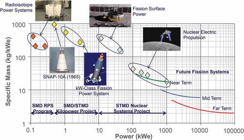
A small 1- to 10-kW(electric)–class FPS could enable future flagship science missions and exploration precursor missions that may not otherwise be possible. In addition, the Human Spaceflight Architecture team,Citation2 in recognition of the advantages of Kilopower for surface power system modularity, mobility, and reliability, has assumed four 10-kW(electric) power systems for the 40-kW(electric) first human Mars surface mission requirement.
The development of a FPS was centered on designing, building, and testing a working nuclear prototype. This paper describes the major steps in developing the FPS and finishes with potential missions for the future.
II. KRUSTY DEVELOPMENT PLAN
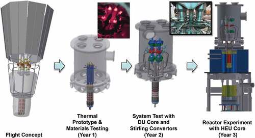
The centerpiece of the Kilopower Project is the development and testing of a ground technology demonstration of a small FPS based on a 1-kW(electric) space science power requirement. This test was named the Kilowatt Reactor Using Stirling TechnologY or KRUSTY test. NASA’s Glenn Research Center (GRC) led the effort to design the test. GRC also built and demonstrated the balance of plant heat transfer, power conversion, and heat rejection portions of the KRUSTY system. NASA’s Marshall Space Flight Center (MSFC) developed the electrical reactor simulation heat source for the nonnuclear testing at GRC and the shielding for nuclear testing. The U.S. Department of Energy’s (DOE’s) Los Alamos National Laboratory (LANL) led the design of the reactor and performed nuclear testing, the DOE’s Y-12 National Security Complex fabricated the highly enriched uranium (HEU) reactor core, and the Nevada Nuclear Security Site Mission Support and Test Services supported nuclear testing. The major phases of the KRUSTY test are shown in .
Fig. 2. KRUSTY development phases.
II.A. Flight Concept Development
Demonstrating space fission power technology for space from 1 to 10 kW(electric) required a baseline for the demonstrator design with the following characteristics:
encompasses the technology challenges inherent in the range of potential systems from 1 to 10 kW(electric) as much as possible
represents a particular potential mission target
can be fabricated affordably
can be tested affordably.
Two configurations for extremes of candidate missions were examined during preliminary trade studies and initial concept development for Kilopower applications and for the KRUSTY baseline: 1-kW(electric) fission power for deep space science missions and 10-kW(electric) fission power for planetary surface human exploration. In 2014, deep space science candidate missionsCitation1 had been identified that could be enabled by 1-kW(electric) fission power capability. The 1-kW(electric) design target encompassed many of the technology challenges for the 1- to 10-kW(electric) range, including monolithic uranium-molybdenum HEU core fabrication, core to sodium heat pipe heat transfer, heat pipe to power conversion heat transfer, and system-level operability and controllability. The 1-kW(electric) concept also would use existing Stirling engine power conversion system designs directly from the NASA Advanced Stirling Radioisotope Generator (ASRG) program and was small enough to be accommodated in existing DOE test facilities in Nevada. For these reasons, the 1-kW(electric) configuration was chosen as the baseline for the KRUSTY demonstration.Citation3–Citation9 However, to ensure that the Kilopower Project addressed the technology challenges across the range of applications, a study of a Mars 10-kW(electric) concept was undertaken in the first year of the project to identify those technology challenges that would need to be addressed after the KRUSTY demonstration and to define the effort required to address them. A preliminary Mars concept was developed, and requirements for this system were defined in partnership with NASA’s Human Spaceflight Architecture Team.Citation2,Citation10
II.B. KRUSTY Thermal Prototype Development and Test
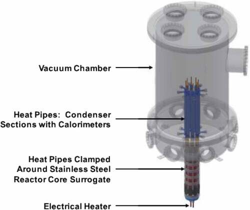
In 2015, the first step to developing a KRUSTY technology demonstration was to validate the transfer of heat from the reactor core to the Haynes 230 heat pipes with sodium working fluid. Stainless steel was used to fabricate a reactor core simulator due to its similar thermal properties to uranium/molybdenum. An electrical heater was developed at NASA MSFC to heat the core in the central channel that, in the flight configuration, would accommodate a boron carbide poison rod. Removal of this rod from the center of an HEU core would start the reactor, but the central channel provides a convenient location for the electrical heater. A vacuum chamber with gas-cooled walls was constructed to accommodate this assembly (see ).
Fig. 3. Thermal prototype assembly.
Several methods of clamping the heat pipes into grooves cut in the circumference of the core were tested. As a result of this testing, clamping of the heat pipes to the core by encircling the heat pipes with heated stainless steel rings and allowing them to cool and contract around the assembly provided the best thermal contact between core and heat pipes. This result permitted the project to proceed with testing using nonfissioning depleted uranium (DU) and Stirling engine power conversion.Citation11
II.C. KRUSTY DU Test
The KRUSTY specific objectives of the DU test included the following:
demonstration of DOE Y-12 readiness to produce a HEU core in three sections by casting metallurgically identical DU core sections
refinement of preparation and assembly of the KRUSTY experiment, using the nonfissioning DU core sections as surrogates for HEU core sections
electrically heated testing of the KRUSTY experiment assembly though the spectrum of test conditions anticipated for the final KRUSTY nuclear test at the National Criticality Experiments Research Center (NCERC) at the Nevada National Security Site (NNSS)
testing of alternative configurations of the Stirling power conversion interface with heat pipes to determine the configuration to be used for the nuclear test in Nevada.
The DU HEU alloyed with molybdenum 8% by weight core sections were successfully cast by the Y-12 National Security Complex. While the casting produced core sections that met the specifications for the KRUSTY experiment, the mold geometry and curing furnace temperature profile resulted in small voids in the final casted sections, mostly near the upper surfaces. Changes to the mold geometry and furnace temperature profiles were indicated such that when they were implemented for the HEU core section casting, they produced excellent results.
The KRUSTY experiment 1-kW(electric) Kilopower reference baseline includes eight Stirling engines for electrical power generation. For the KRUSTY experiment, two Stirling engines designed for nominally 70-W(electric) output each were available from the NASA ASRG program. For the KRUSTY experiment, it was determined that six nitrogen gas-cooled thermal simulators, controlled to follow the thermal load of the two real Stirling engines, would be substituted for six more Stirling engines at a much lower cost.
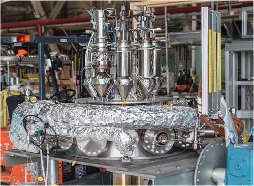
Two configuration options of the KRUSTY experiment were assembled and tested in vacuum with the electrically heated DU cores in the GRC Electric Power and Propulsion Research Building. These configurations differed in the interface between the Stirling engines/simulators and the heat pipes. In the first configuration, the Stirling engines/simulators were grouped in pairs, a traditional configuration for Stirling engines that dynamically balances the linear motions of their pistons to eliminate vibrations in the adjacent spacecraft or planetary surface mounting structure. For this first configuration, the Stirling engine/simulator hot ends were connected to a metal plate that collected heat from two heat pipes. For the second configuration, a second set of heat pipes was built with flared ends that interfaced directly with individual Stirling/simulator acceptor plates. This single engine array configuration requires an electrically operated mass balancer to cancel the vibrations from the unpaired engine. The test of these two configurations was required to determine which configuration produced the required electrical power from the Stirling engines at the lowest weight. The increased efficiency of the second configuration’s improved heat pipe–engine interface more than compensated for the mass and power consumptions of the mass balancers, and the single engine array configuration of KRUSTY was selected for the Nevada test at NCERC (CitationRef. 12). This configuration is shown in .
Fig. 4. Stirling engines and simulators attached to vacuum chamber bottom.
II.D. KRUSTY Preparation for Nuclear Test
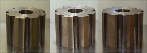
The Y-12 National Security Complex cast the KRUSTY HEU core sections during the summer of 2017. shows the core sections after final machining.
Fig. 5. KRUSTY HEU core sections.
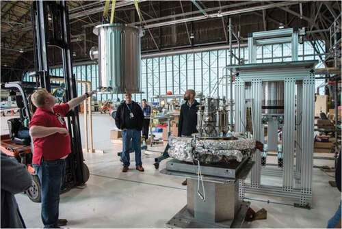
The nonnuclear systems were all thoroughly tested and checked out using an electrically heated core simulator earlier in the year, followed by assembly dress rehearsals in a mocked-up NNSS test facility environment located at the GRC aircraft hangar, as shown in . The KRUSTY experiment hardware was then shipped from GRC and arrived at the NNSS in October 2017. It was inspected before transportation to the Device Assembly Facility. Criticality testing of all nuclear significant components began in early November to verify the physics of the Kilopower reactor components.
Fig. 6. Dress rehearsal of KRUSTY hardware with simulated Comet test stand in the GRC hangar.
II.E. KRUSTY HEU Testing
KRUSTY HEU testing consists of four phases:
reactor component critical testing
cold criticals of reactor system
warm criticals of reactor
high-temperature, full-power testing.
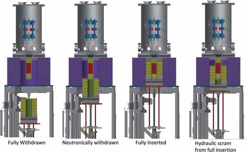
The test phases are of sufficient length to permit thorough, incremental understanding of the reactor core reactivity-controlled increases and the response of the KRUSTY system to the reactivity increases. In each of these phases, the reflector is raised to a position around the core and inside the shield. The position corresponds to a calculated level of reactivity. Measurements are taken, and the reflector is lowered. The measured reactivity is compared to predictions. This process is repeated with increasing levels of reactivity sufficient to confirm the understanding of the experiment performance against predictions. shows the configuration of the KRUSTY experiment on the Comet platform for various states of reactivity.
Fig. 7. KRUSTY assembly on the Comet platform at different stages of reactivity.
II.E.1. Component Critical Testing
The first-phase testing was the characterization of the reactivity of the KRUSTY reactor components, including the core, reflector, and shielding. The reactor core and shielding were installed onto the top platform of the Comet experiment platform. The reflector was assembled on an elevating lift table, below the core. Iterative testing of the reactivity of the core was then performed. The core went critical on November 16, 2017. The results of the component criticals were used to evaluate the analytical model used by LANL to predict reactivity of the KRUSTY experiment. The agreement between the analytical model and the results were outstanding, with only minor variations. A sample table of the results is provided in , which is a reprint from work performed by Sanchez et al.Citation13
TABLE I Measured and Calculated keff for KRUSTY Component Critical Experiments
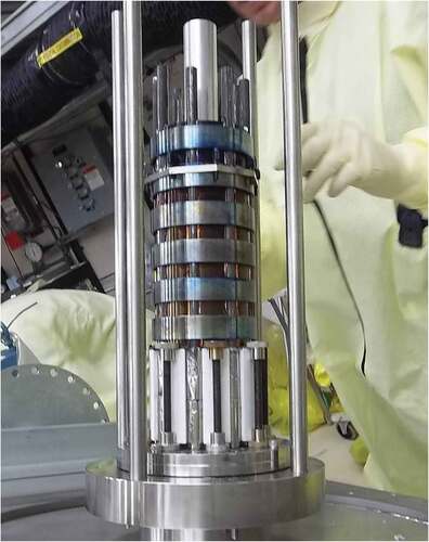
The core was then removed from the platform and installed into the KRUSTY heat pipe and Stirling engine/simulator assembly, and this assembly was installed on top of the Comet platform to complete the readiness of the experiment for the subsequent critical test phases. A picture of the assembled core and heat pipes is shown in .
Fig. 8. Assembled KRUSTY core (upside down) showing attached heat pipes using ring clamps.
II.E.2. Cold Criticals
With the core, heat pipes, and Stirling engine/simulator assembly integrated, the same process of iterative reactivity increases was repeated. Cold critical testing began on January 12, 2018. This phase of testing continued until the end of February 2018. The results of the cold criticals were used to again update analytical models and to prepare the system for the warm critical experiments. A sample table of results is provided in , which is a reprint from work performed by Grove et al.Citation14 The final assembly of the Stirling engine converters is shown in .
TABLE II Reactivity Measurements for KRUSTY Cold Critical
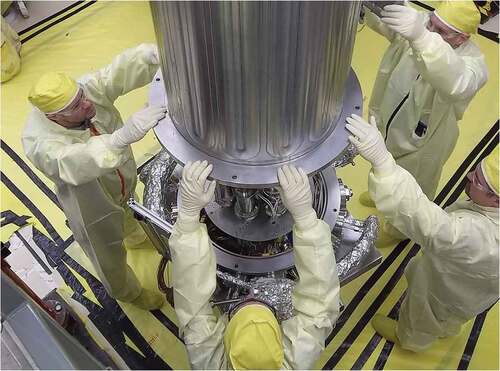
Fig. 9. LANL and NASA engineers lowering the top of the vacuum chamber over the Stirling engines.
II.E.3. Warm Criticals
Warm critical experiments began on March 7, 2018. The core platen was loaded with less than 80 ¢ of total reactivity for the warm critical experiments. The warm critical experiments were used to determine the temperature feedback of the reactor assembly for three progressively hotter experiments. The experiments had the following excess reactivity insertions:
15 ¢ insertion on March 7
30 ¢ insertion (15 ¢ initial followed by 2 ¢ insertions until 30 ¢ reached) on March 8
60 ¢ insertion (15 ¢ initial followed by 2 ¢ insertions until 60 ¢ reached) on March 14.
The information obtained from the warm critical runs was used to determine the appropriate reflector configuration (the necessary amount of reactivity excess) for the high-temperature run and was used to validate the accuracy of the analytical models in predicting the behavior of the KRUSTY core during the high-temperature run. The 60 ¢ insertion test was modeled before the test to predict temperature behavior in the core. This prediction was then compared to actual data after the experiment. The DOE required close agreement between the model and the data prior to proceeding to the high-temperature experiments. The peak temperature outer surface edge of the core at the axial midplane was used for comparison. The predicted peak temperature was 446°C; the actual was 447°C. The DOE approved the experiment approximately 2 days after the end of the 60 ¢ insertion test. The platen was then loaded with approximately 2.00 $ in excess reactivity. presents a picture of the KRUSTY experiment on the Comet machine with the lower platen fully loaded with beryllium oxide.
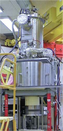
Fig. 10. Fully assembled KRUSTY test showing reflector (BeO) in white on platen. Shield block and vacuum chamber above.
II.E.4. Full-Power, High-Temperature, 28-h Test
The final full-power [~4 kW(thermal)], 800°C core temperature, 28-h experiment was begun on March 20, 2018, and ended on March 21, 2018. The final phase of testing consisted of a simulated space mission profile for a Kilopower system. Start-up of the FPS was accomplished by increasing reactivity slowly over 1½ h until the core reached 800°C. The Stirling engines were started at approximately 1.2 h. Steady-state full-power operation was held for approximately 5½ h to validate normal operation. Over the remaining 21 h, a set of transient experiments was performed on the core to demonstrate the self-regulating characteristics of the Kilopower reactor. These transients included the following:
simulating the failure of one and two Stirling engines
increasing the stroke on the Stirling engines to increase power draw on the reactor core
adjusting the reactivity in the core to change the peak core temperature to 840°C
turning off of all heat removal to the reactor core except for the radiative heat transfer from the core to the vacuum chamber.
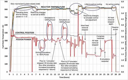
shows LANL and NASA staff monitoring the performance of the reactor during the experiment. shows a temperature and reactivity plot of the complete experiment reprinted from Poston et al.Citation15
Fig. 11. LANL and NASA engineers monitoring reactor performance in the NCERC control room.
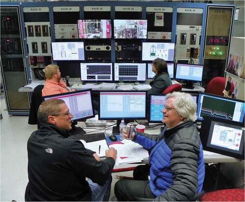
Fig. 12. Power and temperature data from the 28-h KRUSTY nuclear system test.
II.E.5. Final Assessment of the KRUSTY Experiment
The KRUSTY experiment demonstrated that the Kilopower reactor concept would perform as designed. The desired performance parameters versus the outcome of the experiment are shown in .
TABLE III KRUSTY Experiment Outcomes
III. EXAMPLE KILOPOWER MISSIONS
Kilopower was designed for numerous missions both for planetary surface power and for deep space missions. Examples of both types of missions are presented below. The detail presented varies by mission. The analysis for these missions was done by different NASA centers with varying objectives. As such, consistent mission data were not available.
III.A. Example Planetary Surface Missions
III.A.1. Mars
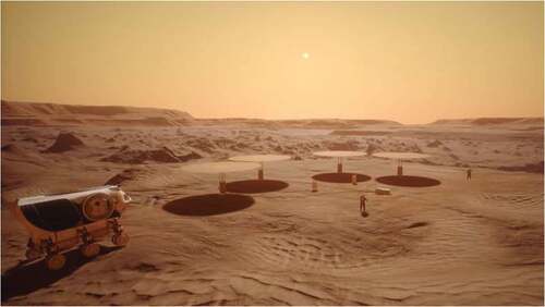
The first mission discussed for Kilopower was as a power supply for human missions to Mars. The Human Spaceflight Architecture team has assumed four 10-kW(electric) power systems for the 40-kW(electric) first human Mars surface mission requirement, with a possible fifth unit for reliability. shows a potential configuration for the Mars mission with four 10-kW(electric) reactors in a core-buried configuration with parasol-style radiator panels.
Fig. 13. Potential configuration of Kilopower reactors on Mars.
III.A.2. Moon
The other planetary surface mission that has been proposed for Kilopower is a technology demonstration mission for the lunar surface. Currently, a 1-kW(electric) reactor has been proposed for deployment in the mid-2020s. The reactor would be part of a lander demonstration. Potential missions could be as either a power source for rovers or a power source for an In-Situ Resource Utilization demonstration unit.
III.B. Example Deep Space Missions
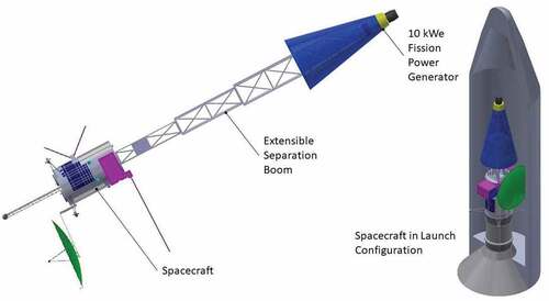
The National Academy of Sciences 2013–2022 Decadal SurveyCitation16 identified many RPS-powered mission concepts that could be performed using a 1-kW(electric) or 10-kW(electric) reactor. A reactor-powered Nuclear Electric Propulsion (NEP) system for these missions would support an increased science payload mass, increased communications rate, and shorter flight times. With a lesser increase of science payload mass, an NEP system could also support a greater than 40-year mission lifetime. A 10-kW(electric) NEP system can provide the power for multiyear outer solar system robotic missions, such as those presented in the following examples.Citation17 A representative NEP flight system is shown in .
Fig. 14. Representative NEP flight system configuration. The science payload in this figure is shown at the front of the bus.
III.B.1. Neptune + Triton Orbiter
A 10-kW(electric) reactor with a Falcon Heavy launch could get a 3700-kg spacecraft into Neptune orbit with 13 years’ flight time. With a 1.5-year Neptune tour, the system could then get 3500 kg into Triton orbit. This would allow a 6-month orbital mission; delta-velocity studies indicate that it would also support Triton landers.Citation18 This mission concept uses the same trajectory as the Ice Giants (a 2030 launch opportunity with Jupiter flyby), but with NEP instead of solar electric propulsion, which would be able to deliver only half as much mass into Neptune orbit and would not be able to get the spacecraft into Triton orbit.
III.B.2. Chiron Orbiter
Work is pending on using an existing Chiron mission study design for a Stirling-powered electric propulsion mission from the 2003 decadal survey.Citation19 With 10-kW(electric) power, it is possible to orbit two Centaur objects with a Dawn spacecraft-like double orbiter.
III.B.3. Titan + Enceladus Orbiter
A 10-kW(electric) NEP can put 7200 kg in Enceladus orbit 10.5 years after launch or reduce flight time to 7 years with 3000 kg in orbit. A 10-kW(electric) reactor with a Falcon Heavy launch could get a 4000-kg spacecraft to orbit both Titan and Enceladus (1 year at each moon) with a less than 14-year mission. The system can provide a 50 kilobit/s data rate to ground and 5 kW(electric) to spacecraft when not thrusting and 1 kW(electric) to spacecraft when thrusting. Results are similar for Titan and faster for Europa missions. Saturn NEP launch opportunities recur every year.
III.B.4. Pluto Orbiter
A 10-kW(electric) reactor with a Space Launch System launch could get a 2600-kg spacecraft into Pluto orbit with a 14-year flight time.
III.B.5. Titan Saturn System Mission
In 2014, the NASA GRC’s Collaborative Modeling for Parametric Assessment of Space SystemsCitation20 (COMPASS) team completed a reassessment study of the 2010 decadal survey Titan Saturn System Mission using a uranium-fueled 1-kW(electric) nuclear reactor in place of the original plutonium-fueled 500-W Stirling radioisotope system. The goal was to explore Saturn’s moon Titan by incorporating an orbiter, lander, and Montogolfier balloon for a total of over 100 kg of science payload.
After 16 Titan flybys, release of the Montogolfier balloon and lander, 7 Enceladus flybys, Titan orbit insertion, and 200 Titan aerobrake maneuvers, a 1500-km orbit would finally be achieved for a 20-month science operation. The mission duration for the fission system totaled 15 years and 3 months.
III.B.6. Kuiper Belt Object Orbiter
A design study from NASA GRC’s COMPASS team also included a Kuiper Belt Object Orbiter that would include a 10-kW(electric) NEP system. The trans-Neptunian Kuiper Belt object 2001 XH255 was chosen as the target. These bodies are assumed to be composed of frozen methane, water, and ammonia; because of their vast distance from the sun, they have presumably never been thawed. The electric propulsion system would operate continuously after launch until a Jupiter gravity assist, followed by a long coast period, and finally deceleration and orbit insertion 16 years later. Once in orbit at KBO 2001 XH255, the 1-year science mission would begin.
IV. CONCLUSION
The technology development and demonstration Kilopower Project has stepped through a build-and-test sequence of phases that completed the demonstration of a flightlike system operated at prototypic conditions in a relevant environment (Technology Readiness Level 5) for space science and human exploration power needs. The innovations of monolithic reactor fuel form and heat pipe heat transfer with no moving parts have been applied and tested through all challenges. The nuclear steady state and transient test of a space reactor is the first such experiment performed in the United States since the 1960s. This accomplishment establishes the readiness of nuclear-tested FPS technology for affordable, lightweight application to human and robotic exploration wherever it is needed.
Acknowledgments
We would like to thank the entire Kilopower team for its commitment to realizing the first demonstration of space fission power technology in over 50 years. We would also like to thank NASA’s Space Technology Mission Directorate and Game Changing Development Program, as well as the DOE National Nuclear Security Administration, Nuclear Criticality Safety Program, for their sponsorship and vision in seeing the Kilopower technology through to the conclusion of its first groundbreaking step toward abundant, affordable power for space missions to the solar system’s most challenging and interesting locations.
References
- L. S. MASON et al., “Kilowatt-Class Fission Power Systems for Science and Human Precursor Missions,” presented at American Nuclear Society Topl. Mtg. Nuclear and Emerging Technologies for Space (NETS-2013), Albuquerque, New Mexico, February 25–28, 2013.
- M. A. RUCKER, “Integrated Surface Power Strategy for Mars,” Proc. Topl. Mtg. Nuclear and Emerging Technologies for Space, February 23–26, 2015, Albuquerque, New Mexico, p. 5074, American Nuclear Society (2015).
- L. S. MASON et al., “Versatile Stirling Technology for Radioisotope and Fission Power Systems,” Proc. Topl. Mtg. Nuclear and Emerging Technologies for Space, John C. Stennis Space Center, Mississippi, February 24–26, 2014, p. 1024, American Nuclear Society (2014).
- J. T. CREASY et al., “Fuel Selection and Development for Small Fission Power System,” Proc. Topl. Mtg. Nuclear and Emerging Technologies for Space, John C. Stennis Space Center, Mississippi, February 24–26, 2014, p. 2006, American Nuclear Society (2014).
- D. I. POSTON et al., “Notional Design of the Kilopower Space Reactor,” Proc. Topl. Mtg. Nuclear and Emerging Technologies for Space, John C. Stennis Space Center, Mississippi, February 24–26, 2014, p. 2007, American Nuclear Society (2014).
- M. A. GIBSON et al., “Development of NASA’s Small Fission Power System for Science and Human Exploration,” Proc. Topl. Mtg. Nuclear and Emerging Technologies for Space, John C. Stennis Space Center, Mississippi, February 24–26, 2014, p. 2015, American Nuclear Society (2014).
- P. R. McCLURE et al., “The Use of the Nevada National Security Site as a Reactor Test Center,” Proc. Topl. Mtg. Nuclear and Emerging Technologies for Space, John C. Stennis Space Center, Mississippi, February 24–26, 2014, p. 2016, American Nuclear Society (2014).
- M. A. GIBSON et al., “Development of NASA’s Small Fission Power System for Science and Human Exploration,” Proc. Propulsion Energy Forum, Cleveland, Ohio, July 28–30, 2014, AIAA-2014-3458, American Institute of Aeronautics and Astronautics (2014); https://arc.aiaa.org/doi/abs/10.2514/6.2014-3458 (current as of Feb. 2020).
- D. I. POSTON et al., “Reactor Design of the Kilowatt Reactor Using Stirling Technology (KRUSTY),” Proc. Topl. Mtg. Nuclear and Emerging Technologies for Space, Huntsville, Alabama, February 22–25, 2016, p. 6090, American Nuclear Society (2016).
- D. I. POSTON et al., “Shielding Options for Kilopower Mars Surface Reactors,” Proc. Topl. Mtg. Nuclear and Emerging Technologies for Space, Huntsville, Alabama, February 22–25, 2016, p. 6089, American Nuclear Society (2016).
- D. T. PALAC et al., “Nuclear Systems Kilopower Update,” Proc. Topl. Mtg. Nuclear and Emerging Technologies for Space, Huntsville, Alabama, February 22–25, 2016, p. 6057, American Nuclear Society (2016).
- M. BRIGGS and M. A. GIBSON, “Status of the Kilowatt Reactor Using Stirling Technology (KRUSTY),” Proc. Topl. Mtg. Nuclear and Emerging Technologies for Space, Orlando, Florida, February 27–March 2, 2017, p. 21151 American Nuclear Society (2017).
- R. SANCHEZ et al., “Kilowatt Reactor Using Stirling TechnologY (KRUSTY) Component-Critical Experiments,” Nucl. Technol., 206, S56 (2020); https://doi.org/10.1080/00295450.2020.1722553.
- T. GROVE et al., “Kilowatt Reactor Using Stirling TechnologY (KRUSTY) Cold Critical Measurements,” Nucl. Technol., 206, S68 (2020); https://doi.org/10.1080/00295450.2020.1712950.
- D. I. POSTON et al., “Results of the KRUSTY Nuclear System Test,” Nucl. Technol., 206, S89 (2020); https://doi.org/10.1080/00295450.2020.1730673.
- NATIONAL RESEARCH COUNCIL, Vision and Voyages for Planetary Science in the Decade 2013–2022, The National Academies Press, Washington, D.C. (2011).
- J. R. CASANI, “Space Fission Power: NASA’s Best Bet to Continue to Explore the Outer Solar System,” Proc. Topl. Mtg. Nuclear and Emerging Technologies for Space, Richland, Washington, February 25–28, 2019, American Nuclear Society (2019).
- N. STRANGE, Triton Orbiter DV Budget, JPL, Personal Communication (Dec. 2018).
- NATIONAL RESEARCH COUNCIL, New Frontiers in the Solar System: An Integrated Exploration Strategy, The National Academies Press, Washington, D.C. (2003).
- M. A. GIBSON et al., “NASA’s Kilopower Reactor Development and the Path to Higher Power Missions,” Proc. IEEE Aerospace Conf. 2017, Big Sky, Montana, March 6–10, 2017, Institute of Electrical and Electronic Engineers (2017).