Abstract
The purpose of this study is to clarify the possibility of designing a small rotational fuel-shuffling breed-and-burn fast reactor (RFBB) with nitride fuel and sodium coolant based on neutronic and heat removal analyses. In these reactor analyses, uranium nitride fuel with a helium bond and sodium coolant was applied to the RFBB, whose thermal power is 450 MW. The structural and cladding materials are oxide dispersion-strengthened ferritic steel. Calculation results showed that the core with rotational fuel shuffling achieved an equilibrium state at criticality near unity, and the average discharge burnup of discharged fuel was 187 MWd/kg heavy metal. In this equilibrium state, reactor characteristics, such as neutron flux and the power profile, were almost stable, and the maximum displacements-per-atom value was slightly higher than 650. A steady-state heat removal analysis was performed for the hottest channel in the core, revealing that the fuel temperature was lower than the operational limit temperature and that the cladding temperature was lower than its melting temperature. However, it was slightly higher than the suggested value of 600°C for retaining nitride fuel integrity for high burnup. It was shown that the core radius could be smaller than that of the metal-fueled core of the previous study.
I. INTRODUCTION
Breed-and-burn (B&B) fast reactors can be fueled only with depleted uranium (DU) or natural uranium (NU), without the need for fuel reprocessing and enrichment. The concept of the B&B reactor was proposed by FeinburgCitation1 for the first time in 1958. TellerCitation2 redeveloped the idea and proposed a new fast reactor design in which B&B waves could move through the axial direction of the fuel. Depending on the direction of the burning wave, the concept can be categorized into two different types. One is a traveling wave in which a burning wave is in the axial direction of a core, such as CANDLE (CitationRef. 3). The other is a standing wave in which the burning wave is in the radial direction; this latter design was generally developed at Terra Power LLC (CitationRef. 4) and at the University of California, Berkeley.Citation5
For both designs, the breeding and burning process can be called the B&B mode, in which fertile material, e.g., 238U, is transmuted into fissile material, 239Pu or 241Pu, that is continuously consumed in situ and enables establishing a critical fission chain reaction. As a result, neutron absorption by fertile material and by the accumulation of fission products can be significant while the reactor is in operation. Therefore, the neutron economy must be improved to sustain the chain reaction in the B&B mode of operation. A common way to increase the neutron economy in a core is to reduce the neutron leakage by enlarging the core size or keeping high-reactivity fuels in a high-neutron-importance region continuously by fuel shuffling.
To achieve criticality and improve the neutron economy in the B&B mode of operation, the rotational fuel shuffling conceptCitation6,Citation7 has been proposed. Fresh fuel of NU or DU is loaded from the periphery of the core and subsequently moved toward the core center. The fuel is then moved outward before being discharged around the edge of the core. This pattern enhances the neutron economy, keeps the maximum cladding damage within a constrained value,Citation7,Citation8 and makes it possible to establish the B&B operation mode in a smaller reactor core. Feasibility studies on small rotational fuel-shuffling breed-and-burn fast reactors (RFBBs) have been investigated in detail.Citation9,Citation10
To determine which fuel and coolant materials to use, neutronic and heat removal analyses of different combinations of such materials for the B&B mode of operation were performed,Citation10 revealing that 15N enriched nitride fuel (to increase neutron economy and avoiding the formation of 14C from the 14N) is the best combination for designing a small B&B reactor when taking into account neutron leakage from the viewpoint of neutron balance. In terms of heat removal analyses, sodium coolant has better heat removal performance than other liquid-metal coolant materials, which are lead and lead bismuth, when minimum pin pitch, an important parameter for designing a small reactor, is applied. But the feasibility and performance analyses have not been investigated for a RFBB with sodium coolant and nitride fuel. Thus, the purpose of the present study is to clarify the possibility of designing a small RFBB reactor with nitride fuel and sodium coolant.
II. CORE DESCRIPTION
Previous studies have analyzed RFBB fast reactors with sodium coolant and metal fuel.Citation7,Citation11 In the present reactor analysis, uranium nitride fuel with a helium bond and sodium coolant is applied to the RFBB, where fuel diameter and smear density at 83% theoretical density (TD) are set according to a study on the evaluation of the integrity of fuel by Nakae et al.Citation12 The structural and cladding material is oxide dispersion-strengthened ferritic steel (ODS). The overall fuel, cladding, and coolant material volume fractions are 66.85%, 19.39%, and 13.76%, respectively. The pin pitch is set at 0.9434 cm for the nitride fuel with a helium bond, while the fuel-to-coolant volume fraction is kept the same as in a previous study.Citation10
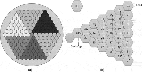
Core specifications are shown in . The reactor core height is 220.0 cm, and the equivalent radius, composed of 168 fuel assemblies and one coolant channel assembly at the center, is 106.5 cm. The core is surrounded by sodium as a reflector. In practice, stainless steel is commonly used as a reflector, but in the present study sodium is used instead for simplicity. illustrates the whole-core layout, the fuel shuffling pattern, and the position ID is fuel assembly identity in one-sixth of the core.
TABLE I Core Specifications
The design goal Is to clarify the possibility of designing a RFBB core with nitride fuel and sodium coolant by analyzing the power density during the equilibrium state at higher burnup. Therefore, control systems and fuel assembly ducts are not included in this study. From the viewpoint of heat removal analysis, it also needs to be considered that the nitride fuel operational temperature limit is 1727°C (CitationRef. 13), and that the cladding limit temperature in the case of fuel integrity analysisCitation12 should be retained at 600°C.
II.A. Fuel Shuffling Pattern Description
The reactor’s 168 fuel assemblies are divided into six symmetry regions. Within these symmetry regions, each fuel assembly was shuffled from position IDs 1 to 28, as shown in . Natural uranium fuel assemblies are loaded from the periphery of the core and then shuffled inward to the center, at which they are discharged.
II.B. Fuel Cell Description for Heat Removal Analysis
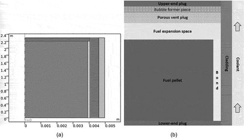
The fuel cell model for the heat removal analyses in this study consists of a fuel pellet, a helium bond, ODS cladding, sodium coolant, lower- and upper-end plugs, a fuel expansion space, a porous vent plug, and a bubble-forming piece as in CitationRef. 14. For venting, the porous vent plug is used instead of a large plenum. This allows for a very short fuel element, resulting in a low pressure drop within the element. It also allows the cladding to be very thin, which is an important parameter for improving neutron economy because it eliminates the need for a large space for the liquid bond material that absorbs neutrons. The schematic layout of the model is provided in . Detailed explanations of the venting can be found in CitationRef. 14.
III. ANALYSIS
The analysis was performed as follows. First, an initial core was constructed and all fuel assemblies were loaded with NU. The burnup analysis was performed for a certain period of time, after which the fuel assembly was shuffled. A NU fuel assembly was loaded at position ID 1 and discharged at fuel assembly position ID 28, as shown in . This was repeated until the burnup reached the equilibrium state. The change in the effective multiplication factor at equilibrium was examined, and if that factor seemed to change during one fuel cycle length (the interval between shuffles), the cycle length was adjusted. This process was repeated until the cycle length was at the value at which the effective multiplication factor remained almost constant during the cycle length. After that, the burnup calculation was performed to determine the effective multiplication factor, burnup of discharged fuel, the displacements per atom (DPA), and the fuel compositions in the discharged fuel for the core. The DPA was calculated using an approximation formula where 2 × 10²³ n/cm3 neutron fluence in energy higher than 100 keV corresponds to 100 DPA (CitationRef. 15). If the results satisfied the parameters of the design goals, heat removal analyses on the hottest channel were performed to check the fuel temperature profile.
III.A. Calculation Tool
The neutron transport and fuel burnup were performed using Serpent 2.1.0 (CitationRefs. 16 and Citation17), a continuous-energy Monte Carlo Reactor Physics Burnup calculation code with the ENDF/B-VII.0 cross-section library. For the fuel, cladding, and coolant materials, continuous-energy cross sections based on the library were prepared at 800 and 700 K, respectively. There are several ways to solve the Bateman equation to calculate fuel depletion in Serpent. We used the Chebyshev Rational Approximation Method. A shuffling program in the Python programming language was added as a function of the Serpent code to perform rotational fuel shuffling.
The following calculation procedure for the neutronic analysis was performed for this study:
Step 1: Prepare input for modeling the active core, which is divided into equal-volume burnup zones where 1 + 5 axial zones and five of the zones are in mirror-reflective condition (in total there are 11 axial zones).
Step 2: Perform a burnup calculation to obtain the fuel composition at each shuffling step for a specified cycle length.
Step 3: Update the fuel composition at each position by shuffling the program along until the core reaches equilibrium condition.
Step 4: Search criticality in the equilibrium core. Once a critical system is found, the power and flux profile and the discharge burnup of the core are obtained from detector files that are based on the collision estimators for calculating user-defined reaction rates integrated over space and energy.
Heat removal analyses were carried out using COMSOL 5.4 Multiphysics Software.Citation18 Fuel cell geometry with a porous vent plug was modeled in two-dimensional axisymmetry with R-Z coordinates, as shown in . For simplicity, the software modeled a cylindrical fuel cell equivalent to a hexagonal cell for neutronic calculation. The heat source was defined by a fitting equation for axial power distribution in the hottest channel, which was obtained from the neutronic analysis. The flow velocity of the sodium coolant was set to 10.0 m/s. The coolant inlet temperature was set at 355°C.
IV. RESULTS AND DISCUSSIONS
From the previous studies,Citation9,Citation11 it was concluded that 56 shuffling steps were enough for the B&B core to reach an equilibrium condition. Therefore, the same number of shuffling steps was used to obtain equilibrium condition, and it was confirmed that the equilibrium condition was reached. After the core reached the equilibrium state, the change in the effective multiplication factor between shuffling steps was obtained by performing burnup calculations with different fuel cycle lengths. Monte Carlo simulations were performed with 50 000 neutron histories in 400 batches, excluding the first 50 batches to obtain results within the statistical error.
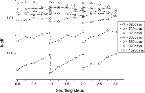
Burnup calculations with fuel cycles of 620, 720, 820, 860, 880, 920, and 1020 days were performed. Result on the change in k-eff between shuffling steps are shown in . Criticality was not achieved when the fuel cycle was 620 days, but was achieved for all other lengths. However, reactivity swings between shuffling steps were large except in the 860- and 880-day cycle lengths, which had small steps. To avoid high DPA, a shorter cycle length is recommended. Therefore, the 860-day cycle length was set for further burnup analyses.
The detailed burnup characteristics of the equilibrium cycle in the case of an 860-day cycle length were analyzed. shows the axial distribution of burnup, average discharge burnup, neutron fluence, and DPA value in the discharged fuel. Burnup is expressed in megawatt-days per kilogram of initial heavy metal (HM). The average discharge burnup obtained from the output and then corrected by the mass ratio was 187.4 MWd/kg-HM, which is close to the hand calculation. The damage dose rate was calculated according to the approximation, and the maximum value was 656 DPA, which is slightly higher than the 650 DPA (CitationRefs. 8 and Citation18) constraint value.
TABLE II Axial Distribution of Burnup, Average Discharge Burnup, Neutron Fluence, and DPA Value in the Discharged Fuel
shows the axial distribution of Pu vector ratios in the discharged fuel. The fraction of 239Pu in Pu in the discharged fuel is more than 80% in the lower and upper fuel. This issue poses a proliferation risk, so it is one of the issues to be resolved in future studies. However, the fraction 239Pu in Pu in the middle zones was below 80%, which is acceptable in discharged fuel.
TABLE III Axial Distribution of Pu Vector Ratios in Discharged Fuel
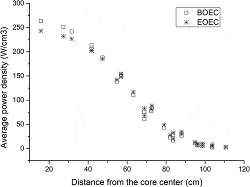
shows the changes in radial power distribution between the beginning of the fuel cycle in the equilibrium condition (BOEC) and the end of the fuel cycle (EOEC). The change in power distribution between the BOEC and the EOEC is small enough. The difference between the average power density distribution at the center and at the periphery of the core is significant. The uniform outlet coolant temperature from the core can be achieved by using ducts that each have an orifice that enables flow velocity to be controlled easily assemblywise.Citation6
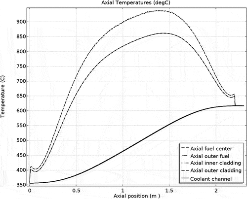
The axial temperature profile in the hottest channel is illustrated in . The model for the hottest channel is shown in . The maximum fuel temperature was ~946°C, which is lower than the operational limit of 1727°C (CitationRef. 13) for nitride fuel in normal conditions. The maximum cladding outlet temperature was ~619°C, slightly higher than the suggested value of 600°C in CitationRef. 12, which is the suggested value for retaining nitride fuel integrity for high burnup. The outlet coolant temperature reached ~619°C, which is higher than that of a commercial sodium-cooled fast reactor.
In the previous study, the feasibility of a sodium-cooled and metal-fueled RFBB (RFBB-MS) was studied.Citation9 The design of the core was based on S-PRISM (CitationRef. 8). To apply rotational fuel shuffling, some modifications were made, including increasing the core height to 200 cm and the core equivalent diameter to 271 cm, to achieve criticality in the B&B mode of operation. The design in the current study of a nitride-fueled RFBB (RFBB-NS) was 20 cm taller and 58 cm smaller in diameter. A small core radius can be expected to reduce construction costs.
In the RFBB-MS, the fuel cycle length was set at 1125 to 1250 days and the core was critical in the equilibrium condition. In the case of RFBB-NS, a core with an 860-day cycle length could achieve an equilibrium state at criticality close to unity. The average discharge fuel burnup in the RFBB-MS was from 275 to 306 GWd/tonHM whereas the RFBB-NS in this study is 32% to 39% smaller than that of the RFBB-MS. However, the DPA of the cladding material was 2900 to 3217 in the RFBB-MS in the previous study, whereas that of the RFBB-NS was slightly higher than 650 DPA.
V. CONCLUSIONS
The possibility of a small RFBB with nitride fuel and sodium coolant was studied. The results revealed that the core with rotational fuel shuffling at an 860-day cycle length could achieve an equilibrium state at criticality close to unity. In this equilibrium state, the power density profile during BOEC and EOEC was unchanged. The average discharge burnup was 187.4 MWd/kg-HM. With this amount of burnup, the plutonium vector was acceptable in the mid-zones of the fuel. A steady-state heat removal analysis was performed for the hottest channel, revealing that the maximum fuel temperature was lower than the operational temperature limit and that the ODS cladding material temperature was lower than the melting temperature of nitride fuel. However, the maximum cladding temperature was slightly higher than the suggested temperature for nitride fuel integrity. Additional studies will be conducted for more realistic designs that include control rods and ducts. In that case, the neutron balance would be worse due to the absorption of material added to the core, and a modification to the reactor design may be needed.
Acknowledgments
The calculations were performed on the TSUBAME supercomputer at the Tokyo Institute of Technology, Tokyo, Japan. Tsendsuren Amarjargal acknowledges a scholarship provided by the Mongolian‒Japan Engineering Education Development program (M-JEED project, J11B16).
Disclosure Statement
No potential conflict of interest was reported by the authors.
References
- S. M. FEINBERG and E.P. KUNEGIN, Proc. of the 2nd United Nations Int. Conf. on the Peaceful Uses of Atomic Energy, Geneva, Switzerland, Sept. 1–13, 1958; https://digitallibrary.un.org/record/3808554?msclkid=5e25a2ebcf6311ec813d75cc29e48709 (accessed May 9, 2022).
- J. GILLELAND et al., “Novel Reactor Designs to Burn Non-fissile Fuels,” Proc. Int. Conf. on Advances in Nuclear Power Plants, ICAPP 2008, Vol. 4 (2008).
- H. SEKIMOTO, “Light a CANDLE, 2nd ed.,” CRINES, Tokyo Institute of Technology (Jan. 2010); https://www.researchgate.net/publication/305391375_Light_a_CANDLE_2nd_ed ( accessed May 9, 2022).
- T. ELLIS et al., “Traveling-Wave Reactors: A Truly Sustainable and Full-Scale Resource for Global Energy Needs,” Proc. ICAPP ’10, San Diego, California, June 13–17, 2010, American Nuclear Society (2010).
- A. Q. STAFFAN, “Safety and Core Design of Large Liquid-Metal Cooled Fast Breeder Reactors,” Dissertation, –Graduate Division of the University of California, Berkeley (2013); https://escholarship.org/uc/item/64g748hn (accessed May 9, 2022).
- K. KUWAGAKI, J. NISHIYAMA, and T. OBARA, “Concept of Stationary Wave Reactor with Rotational Fuel Shuffling,” Nucl. Sci. Eng., 191, 2, 178 (2018); https://doi.org/10.1080/00295639.2018.1463744.
- K. KUWAGAKI, J. NISHIYAMA, and T. OBARA, “Concept of Breed and Burn Reactor with Spiral Fuel Shuffling,” Ann. Nucl. Energy, 127, 130 (May 2019); https://doi.org/10.1016/j.anucene.2018.12.006.
- J. GILLELAND, R. PETROSKI, and K. WEAVER, “The Traveling Wave Reactor: Design and Development,” Engineering, 2, 1, 88 (Mar. 2016); https://doi.org/10.1016/J.ENG.2016.01.024.
- T. OBARA, K. KUWAGAKI, and J. NISHIYAMA, “Feasibility of Burning Wave Fast Reactor Concept with Rotational Fuel Shuffling,” IAEA-CN245-051, International Atomic Energy Agency (2017).
- O. SAMBUU et al., “Neutron Balance Features in Breed-and-Burn Fast Reactors,” Nucl. Sci. Eng., 196, 3, 322 (2022); https://doi.org/10.1080/00295639.2021.1980361.
- V. K. HOANG et al., “Feasibility of Sodium-Cooled Breed-and-Burn Reactor with Rotational Fuel Shuffling,” Nucl. Sci. Eng., 196, 1, 109 (2022); https://doi.org/10.1080/00295639.2021.1951063.
- N. NAKAE et al., “An Approach for Evaluating the Integrity of Fuel Applied in Innovative Nuclear Energy Systems,” J. Nucl. Mater., 446, 1–3, 1 (Mar. 2014); https://doi.org/10.1016/J.JNUCMAT.2013.11.031.
- R. J. M. KONINGS, and R. E. STOLLER, Comprehensive Nuclear Materials, Vol. 1–5 (2012).
- S. QVIST, J. HOU, and E. GREENSPAN, “Design and Performance of 2D and 3D-Shuffled Breed-and-Burn Cores,” Ann. Nucl. Energy, 85, 93 (May 2015); https://doi.org/10.1016/j.anucene.2015.04.007.
- D. G. CACUCI, Handbook of Nuclear Engineering, Vol. 1: Nuclear Engineering Fundamentals (2010).
- J. LEPPÄNEN et al., “The Serpent Monte Carlo Code: Status, Development and Applications in 2013,” Ann. Nucl. Energy, 82, 142 (2015); https://doi.org/10.1016/j.anucene.2014.08.024.
- M. B. CHADWICK et al., “ENDF/B-VII.1 Nuclear Data for Science and Technology: Cross Sections, Covariances, Fission Product Yields and Decay Data,” Nucl. Data Sheets, 112, 12, 2887 (2011); https://doi.org/10.1016/j.nds.2011.11.002.
- E. GETTO et al., “Void Swelling and Microstructure Evolution at Very High Damage Level in Self-Ion Irradiated Ferritic-Martensitic Steels,” J. Nucl. Mater., 480, 159 (Nov. 2016); https://doi.org/10.1016/J.JNUCMAT.2016.08.015.

