
 ?Mathematical formulae have been encoded as MathML and are displayed in this HTML version using MathJax in order to improve their display. Uncheck the box to turn MathJax off. This feature requires Javascript. Click on a formula to zoom.
Abstract
To improve the nuclear data testing and validation of advanced reactors, such as pebble-bed high-temperature gas-cooled reactors, molten salt reactors, and heat pipe microreactors, a conceptual design for a novel critical assembly using a horizontal split table (HST) was developed jointly by Oak Ridge National Laboratory and Lawrence Livermore National Laboratory. The mechanical design is led by Lawrence Livermore National Laboratory, whereas the neutronics considerations are led by Oak Ridge National Laboratory. The characteristics of the designed HST and the benefits of performing such an experiment to the community are included. As a proof of concept, a proposed critical experiment using tristructural isotropic fuel particles and a graphite moderator/reflector is described, mimicking a pebble-bed-type advanced reactor based on the HTR-10. A critical configuration corresponding to a footprint of about 4.5 m2 was determined with SCALE/KENO-VI to fit the planned dimensions of the HST. The similarity of the pebble-bed design and the HTR-10 reactor application was assessed using SCALE/TSUNAMI, and a similarity coefficient, ck, of 0.9982 was obtained, proving that the concept will be useful for cold-critical validation and for nuclear data validation and assimilation of pebble-bed-type advanced reactors.
In the proposed design, the materials with the highest keff sensitivity are graphite and uranium, which demonstrates that particular care must be given to carbon-related cross-section data. A cross-section library study was performed to test the influence of the different recent releases of the ENDF/B cross-section library on the concept’s keff. The effect of mechanical uncertainties between the fixed and moving tables was also assessed by calculating the reactivity change caused by vertical and horizontal gaps, as well as angular and torsion offsets between the two sides of the HST concept. As a last analysis step, the performed nuclear data assimilation of the hypothetical experiment showed that uncertainties can be reduced by several hundred pcm. The same analysis process is currently being used to create a molten salt advanced reactor–type HST concept based on the Molten Salt Reactor Experiment.
I. INTRODUCTION
An impressively high number of advanced fission reactors are currently being designed by traditional vendors or startup companiesCitation1 using new concepts and technologies compared to those of the current fleet of power reactors. New types of coolants are being studied, such as molten chloride or fluoride salts, liquid sodium, or helium. Different fuels are also being considered, such as tristructural isotropic (TRISO) particles of different fissile materials, fuel salts, or metallic fuels. The power of these new generation reactors can also differ; some designs, such as small modular reactors and even microreactors operate at low powers.
To accurately design and safely operate these reactors, validation data are needed. Performing critical experiments using materials similar to those employed by advanced reactor concepts is one such way to provide such validation data. Currently, few high-quality publicly available benchmark experiments exist to provide support for advanced reactor design, and as identified in the U.S. Department of Energy (DOE) National Nuclear Criticality Safety Program Mission and Vision FY2019-FY2028 document,Citation2 the integral experimental program has several technical gaps that can be filled by designing and using new experimental equipment. To fill these gaps, this work investigates a new horizontal split-table (HST) design for critical experiments to provide validation data for advanced reactor designs and inclusion in the International Criticality Safety Benchmark Experiments Project (ICSBEP) Handbook.Citation3
This paper is based on the IER-539 CED-1 reportCitation4 and other previously published work.Citation5 It summarizes and extends the previous investigation by providing more details and proofs of usefulness for a HST design. This paper presents expanded sensitivity and similarity studies with added ck results and more sensitivity profiles corresponding to different nuclide reactions. It also investigates nuclear data library effects on the experiment keff and has a new section related to the use of the hypothetical experiment results for nuclear data assimilation (DA).
Existing vertical lift machines (VLMs), such as Planet,Citation6 have weight and dimension limitations, as lifting heavy components can be too complex and can become a safety issue. Using a HST instead of a VLM would solve this issue by removing the gravity factor and allowing the size and weight of potential critical experiments to increase, such that they are closer to the characteristics of advanced reactors.
Previous critical experiments using HSTs have been built and operated, such as the Zero Power Reactor-6 (ZPR-6) at Argonne National Laboratory,Citation7 the HST-ORNL at Oak Ridge National Laboratory,Citation8 and the Critical Assembly Machine for Plutonium (CAMP) at Lawrence Livermore National Laboratory,Citation9 but none of them are still being operated today. An important foundation for the newly designed HST comes from a preliminary HST design created in 2013 by Sandia National Laboratory (SNL), IER-226 (CitationRef. 10). This design did not become reality because of funding limitations, but it was the latest consideration for a HST before that described in this paper. The HST conceptual design from this work is based on the aforementioned older HSTs, with new and state-of-the-art equipment corresponding to today’s jump in technology.
After a review of the important lessons learned from the previous critical experiments involving HSTs, the proposed preliminary mechanical design of a new HST is summarized. To motivate the construction of the HST, design calculations of a critical experiment to validate a high-temperature, pebble-bed reactor were performed. These calculations sought to maximize the similarity between an experiment on the HST and an advanced reactor design. If a high similarity was found, then this would help support the need and usefulness of a new HST critical experiment device. The design calculations were performed with different SCALE (CitationRef. 11) modules: KENO-VI for the criticality calculation, TSUNAMI for the sensitivity determination, and TSUNAMI-IP for the concept/application similarity study using the ENDF/B-VII.1 cross-section library.Citation12 The selection of advanced reactor concepts to perform the similarity study is based on a technical memorandum written by Bostelmann et al.Citation13
For more information on the previous HST used in the DOE complex and more mechanical characteristics of the newly designed HST, refer to the IER-539 CED-1 report.Citation4
II. PROPOSED SYSTEM DESCRIPTION
II.A. Proposed Design Specifications from Previous Research and Technology
To assist in the conceptual design of a modern HST, all the legacy critical experiments using HSTs in the DOE complex were reviewed, and the advantages and disadvantages of each were identified. The following HST machines were considered, classified by organization:
1. Argonne National Laboratory: Zero Power Reactor-3 (ZPR-3), ZPR-6, Zero Power Reactor-9 (ZPR-9), and Zero Power Physics ReactorCitation7 (ZPPR)
2. Oak Ridge National Laboratory: HST-ORNL (CitationRef. 8)
3. Lawrence Livermore National Laboratory: CAMP (CitationRef. 9)
4. Los Alamos National Laboratory: Big Ten and Honeycomb
5. Rocky Flats Critical Mass Laboratory: HST.
The most relevant assemblies for a new HST design are the ZPR-6, HST-ORNL, and CAMP, as they display different and interesting ways of mechanical operation. A modern HST should be created by analyzing the different pros and cons of each of these previous HST assemblies to create the best design. The main design decisions for the new HST associated with the review of those legacy experiments and of the SNL preliminary design described in IER-226 are summarized in , adapted from Percher et al.Citation4
TABLE I HST Design Decisions from Previous Experiments or Concepts
II.B. Proposed Design
From the review of legacy HST systems and the list of engineering decisions shown in , a mechanical design for a new HST for performing critical experiments was created. In the proposed design, most components are commercial off the shelf and have modern computer numerical control capabilities. The main aspects of the design are a dual-system safety-redundant scram, one that is fail safe on loss of power, and a high-precision motion and positioning system. The base structures and tables will be made from steel. An important design feature goal obtained from the previous HST design by SNL is targeting a 5 pcm uncertainty in keff induced by the machine itself.
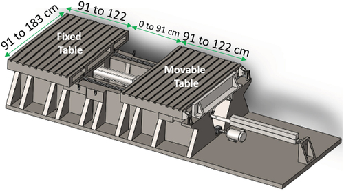
A summary of the mechanical specifications of the newly designed HST is given in , adapted from Percher et al.,Citation4 and a rendering overview of the system modeled in a computer-aided design (CAD) is given in . The mechanical design of the system would work for the specified range of half-table dimensions. The maximum height of 152 cm comes from an expected height limit in the building in which the HST would be located. Thus, the height limit could be overridden, and it is not a strict physical table requirement at this point in the conceptual design. Another parameter to take into account when considering the current design of the table is the 12-tonne mass limit of the experiment (6 tonnes on each table side).
TABLE II Summary of the Newly Designed HST Mechanical Specifications
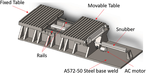
Fig. 1. CAD rendering of the newly designed HST concept.
III. HST DESIGN METHODS FOR ADVANCED REACTOR SUPPORT
Using the HST design specifications in , the tables’ dimensions were used as limits to fit a critical configuration with materials similar to those used in advanced reactor concepts. The dimensions are summarized in . This section summarizes the overall methodology for designing a critical experiment concept to use with the HST, and an application case is given in Sec. IV. The methodology introduced in this section can be used as a procedure for the design of any type of experiment considered on the HST.
Fig. 2. Dimensions of the newly designed HST concept from a CAD rendering.
III.A. Determination of Critical Core Experimental Configuration
A methodology to determine a critical core fitting on the newly designed HST using the SCALE/KENO-VI code was created. The process is reproducible for any type of advanced reactor concept studied. The different steps are as follows:
1. A literature search is conducted to find a peer-reviewed, published, and publicly available reactor benchmark model corresponding to the advanced reactor type selected.
2. The model is converted to a SCALE/KENO-VI format, if necessary.
3. A simplified model of the reactor is created, keeping only the active core region and removing any type of controls.
4. The model is transformed to fit into a cubic shape, and the dimensions are adjusted to be smaller than the HST planned maximum width and length dimensions of 182.88 × 243.84 cm, without limitations on the height of the experiment. The limiting parameter on the current mechanical design of the split table is the total loading weight of the experiment of 12 tonnes.
5. Incremental calculations are performed to determine a critical core corresponding to the HST planned dimensions, adjusting the reflector thickness on the sides, top, and bottom of the active core region. The calculations are performed with SCALE/KENO-VI using the ENDF/B-VII.1 cross-section library as a basis, but other cross-section libraries can be used.
6. The model is separated in half, which corresponds to the two sides of the HST.
III.B. Evaluation of Nuclear Data Tested by the Experimental Configuration
The SCALE S/U analysis sequences, or TSUNAMI tools, are modules in the SCALE code package to calculate keff sensitivity and propagate nuclear data–induced uncertainties. Those tools have been used in the past for various research and commercial reactor applications,Citation14,Citation15 and are extensively described in the literature.Citation16 TSUNAMI-3D was used on the previously determined critical configuration to quantify the predicted change in keff reaction rates or reactivity differences caused by the energy-dependent, nuclide-reaction-specific cross-section data. The sensitivity results are useful to determine which nuclide, nuclear reaction, and/or mixture had the greatest influence on keff. In this work, TSUNAMI-3D was used to calculate the keff uncertainty resulting from the use of nuclear data in the ENDF/B-VII.1 cross-section library. In all the TSUNAMI-3D calculations performed in this work, the continuous-energy CLUTCH method was used, with 10 latent generations and a mesh of about 500 000 voxels, and all the results obtained were confirmed by separate direct perturbation calculations performed with SCALE/KENO-VI. The TSUNAMI output file provides the sensitivity of keff for nuclides and materials in the system. The sensitivity information is saved in a formatted sensitivity data file (.sdf) that can be used for further sensitivity analysis.
Another sensitivity tool used from the SCALE code package is TSUNAMI-IP. In this work, it is used to evaluate the similarity of the designed critical experiment and the application of the HTR-10 modelCitation17 and to determine uncertainties in system reactivity due to cross-section covariance data. The similarity metric calculated here is ck, which is the correlation coefficient of the effect of nuclear data uncertainty on the keff of the application and experiment. A high ck (i.e., close to 1) demonstrates that the HST concept design would be useful for nuclear data validation of the corresponding advanced reactor materials.
As an additional test of the nuclear data’s influence on the critical core configuration, different cross-section libraries were used in the calculations, and the different keff results obtained are discussed. The different cross-section libraries tested were ENDF/B-VII.0 (CitationRef. 18), ENDF/B-VII.1 (CitationRef. 12), and ENDF/B-VIII.0 (CitationRef. 19). A particular focus was given to the carbon cross-section evaluation update between the different ENDF/B cross-section library updates.
III.C. Assessment of HST Mechanical Tolerances
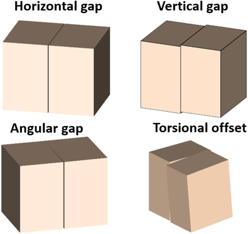
Quantifying experimental uncertainties is an essential part of designing a critical experiment. Of particular interest is understanding the level of reactivity change that would be induced by mechanical uncertainties on the HST experiment for each advanced reactor concept, as first introduced by SNL in a previous HST design.Citation10 If these uncertainties are sufficiently small, the critical experiment can be considered of benchmark quality, and therefore, of great utility for validation. The four types of tolerances investigated in this work were a horizontal gap, a vertical gap, an angular gap, and a torsion offset, as shown in , similar to CitationRef. 10. Calculations varied each of these parameters, and a corresponding keff per gap was obtained for 5 to 10 different points. A quadratic equation was fit to those points.
Fig. 3. Depictions of the mechanical tolerances considered in each HST concept.
Based on the fit, the mechanical tolerance that would produce an acceptable experimental uncertainty was determined for a few different Δkeff values. As a last step of the assessment, the two most significant tolerance contributions on keff were further analyzed. The goal was to determine whether the association of simultaneous tolerance perturbations on the same HST model have a greater influence on keff than the added separate effects. By doing this, any potential nonlinearity in the combined uncertainties can be estimated.
IV. CONCEPTUAL DESIGN STUDY OF A PEBBLE-BED HIGH-TEMPERATURE GAS-COOLED REACTOR
IV.A. HTR-10 Application Case
The first advanced reactor type that was studied was a pebble-bed, high-temperature, gas-cooled reactor. Specifically, it was the HTR-10 reactor, which is thoroughly described by Terry et al.Citation20 and previously modeled in SCALE/KENO-VI (CitationRef. 17). The active core region of this reactor measures 123 cm high and 180 cm in diameter. The core uses a combination of fuel pebbles containing TRISO particles and dummy graphite pebbles separated by air at 15°C. In total, approximately 16 890 pebbles are in the HTR-10: 9627 fuel pebbles and 7263 dummy pebbles, with a packing fraction of 61%.
Each fuel pebble has a radius of 3.0 cm, with a fuel radius of 2.5 cm and a 0.5-cm graphite shell. Each pebble’s inner fuel region contains 8355 TRISO fuel particles. Each TRISO fuel particle is a combination of an inner 17 wt% enriched UO2 fuel kernel with a radius of 0.025 cm and different coating layers of buffer, PyC, SiC, and PyC, with thicknesses of 0.009, 0.004, 0.0035, and 0.004 cm, respectively. The UO2 density is 10.4 g/cm3, and the graphite matrix and fuel pebble’s outer shell density is 1.73 g/cm3.
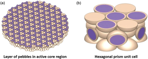
Views of the HTR-10 core KENO-VI model are shown in (CitationRef. 17). shows an isometric view with the front right portion of the model cut away. The left portion of shows a layer of pebbles in the active region of the core. The right portion of shows a detailed cutaway of the pebbles with the fuel region shown in purple and the graphite shown in beige. The pebbles and TRISO particles are all modeled explicitly.
Fig. 4. Depiction of the HTR-10 full-core model.Citation17
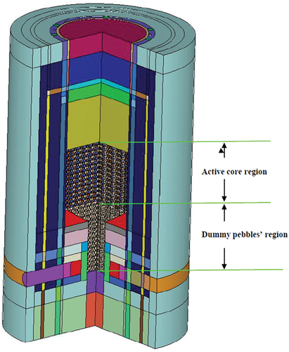
Fig. 5. (a) Depictions of a layer of pebbles in the active region and (b) a prismatic unit cell from an HTR-10 full-core model.Citation17
IV.B. Experimental Concept
A KENO-VI whole-core model of the HTR-10 (CitationRef. 17) was used to create a HST concept model corresponding to the maximum specified width and length dimensions described previously: 182.88 × 243.84 cm. The height of the experiment is not a hard limitation factor. To create the HST concept, the procedure presented in Sec. II.A was closely followed. First, the HTR-10 model was modified such that only the active core region was kept, corresponding to the fuel and dummy pebble association. Then the model was transformed into a cubic shape, and a graphite reflector layer was added on the sides, top, and bottom to obtain a critical configuration at ambient temperature and pressure. Finally, the core was split in half to correspond to the two parts of the HST.
Because this is the conceptual design phase, the way the pebbles are cut at the split location was not considered, and no additional control or safety elements were included in the model. A more realistic way of treating the pebble stacking will be studied in the final design phase of this HST concept. For example, the pebbles would not be cut in half, and a layer of graphite could be added on each side of the tables to avoid any pebbles falling in the middle.
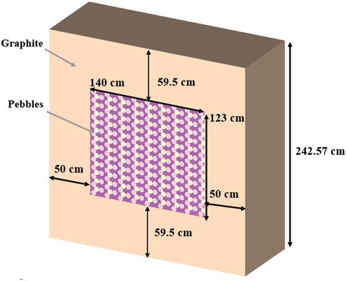
The modeled active fuel region of the critical core was 120 × 140 × 123.57 cm. Including the graphite layer, the core was 182 × 240 × 242.57 cm, slightly smaller than the HST-specified maximum width and length dimensions and corresponding to a total weight of about 12 tonnes, respecting the 12-tonne loading limit. The total weight of the experiment was approximative and will depend on the type of graphite used and on the packing fraction of the pebbles. A top-cut isometric view of the critical HST pebble-bed concept KENO model with dimensions is shown in front-cut isometric view is shown in . Using this configuration, a keff of 1.00019 ± 0.00020 was obtained with KENO-VI and the ENDF/B-VII.1 cross-section library.
Fig. 6. Dimensioned center-cut plane top view of the pebble-bed reactor experimental concept.Citation5
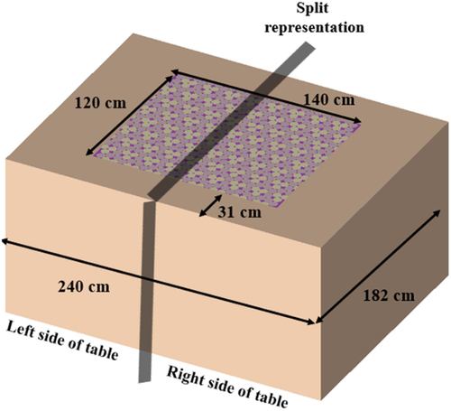
Fig. 7. Dimensioned side view of the pebble-bed reactor experimental concept.Citation5
IV.C. Experimental Concept Analysis
IV.C.1. Similarity Analysis
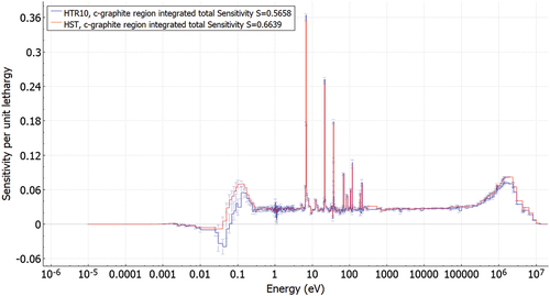
SCALE/TSUNAMI was used to calculate the sensitivities of the critical HST design to the materials’ cross sections. The most interesting results are shown in , with a comparison to the HTR-10 application sensitivity results also obtained with CE-TSUNAMI 3D. The sensitivities for 235U and 238U are very similar between the HST concept and the HTR-10 full-core application. For graphite, differences appear between the integral sensitivities obtained for the HST design and the HTR-10 application. The graphite matrix in pebble, pebble shell, and dummy pebble sensitivities are about 10% to 20% higher in the HTR-10 application, whereas the graphite reflector region sensitivity is about 200% higher in the HST design. Despite these differences, the region-integrated sensitivity for graphite is only about 15% higher for the HST compared to the HTR-10 application.
TABLE III HST Design and HTR-10 Application: Highest Sensitivity Contributors’ Results Obtained with SCALE/TSUNAMI
The reason for these differences comes from the different models used in the HST and in the HTR-10. The HST model is highly simplified, including only a modified active core region from the HTR-10 and a large reflector region, for a total of seven different regions, including graphite. The HTR-10 model includes numerous other graphite regions (43 total), and the absolute contribution of each of these regions is smaller compared to the HST model. Moreover, the HTR-10 model contains a lot more pebbles and less reflector materials than the HST model, explaining the differences in sensitivities. In the end, the region-integrated values are close, and the remaining differences can be explained by the fact that the graphite reflector region is larger in the HST design than in the HTR-10 application model, providing more sensitivity to neutron scattering.
The sensitivity profile plots corresponding to a few of the highest sensitivity contributors are shown in for 235U fission, for 235U radiative capture reaction (n,γ), for 235U total, for graphite region–integrated elastic, and for graphite region–integrated total. In each figure, the sensitivity profiles of the original HTR-10 whole-core application and the newly designed HST concept application are shown. The sensitivity profiles between the design and application are very similar for 235U fission and 235U total reactions. For the graphite total cross section, the shape of the largest sensitivity peaks is similar between the application and HST, where the HST values overall are slightly higher. The main differences appear around 0.1 eV, where a lower sensitivity is observed in the HTR-10 profile compared to the HST. Note the relatively high uncertainty bars in that region. Even accounting for the uncertainties, differences between the HST and the HTR-10 profiles still exist, which are likely the result of the different graphite regions between both models, as described previously. Similar observations are made for the elastic reaction sensitivity profiles, with higher absolute values.
Fig. 8. The 235U fission cross-section sensitivity profiles for the HST concept and the HTR10 application.

Fig. 9. The 235U (n,γ) radiative capture reaction cross-section sensitivity profiles for the HST concept and the HTR10 application.
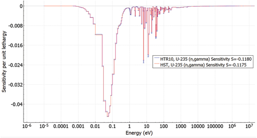
Fig. 10. The 235U total cross-section sensitivity profiles for the HST concept and the HTR10 application.
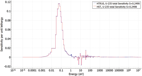
Fig. 11. Region-integrated graphite elastic cross-section sensitivity profiles for the HST concept and the HTR10 application.
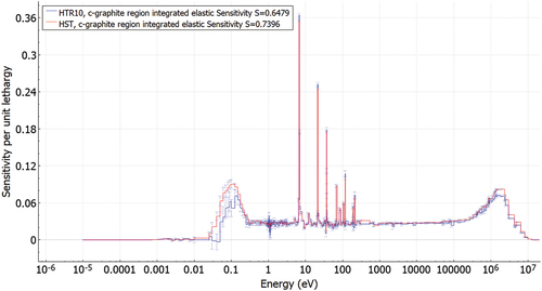
Fig. 12. Region-integrated graphite total cross-section sensitivity profiles for the HST concept and the HTR10 application.
TSUNAMI-IP with the 56groupcov7.1 covariance matrix file was used to calculate the correlation coefficient ck between the designed critical HST and the reference application HTR-10 full-core reactor model, both for the cold zero-power condition. The first step for any experiment designed to validate a reactor is cold critical to validate room temperature cross sections, so looking at ambient temperature is useful even if the reactor will operate at a high temperature. The calculation of the correlation coefficient between two systems demonstrates the amount of nuclear data–induced uncertainty shared by these two systems. Admitting that most of the calculation biases come from nuclear data uncertainties,Citation16 ck can be directly linked to the calculation bias.
The ck values are between 0 and 1, with 1 corresponding to the two systems sharing 100% of their nuclear data uncertainties. The current recommendations for selecting a benchmark experiment for validation are to use systems with a ck above 0.9 (highly similar systems) or ck values between 0.8 and 0.9 (marginally similar systems). Therefore, validating a new type of advanced reactor can be done using the ck methodology by showing the application is highly similar to an existing validated experiment, and a calculation bias can be estimated.
The correlation coefficient obtained between the HTR-10 and the HST is ck = 0.9982 ± 0.0045. As the maximum possible value ck is 1, the obtained correlation between the two models is very high; therefore, the use of a critical HST as designed could support validation of a designed pebble-bed advanced reactor similar to the HTR-10. The highest ck value obtained from the available ICSBEP Handbook benchmarksCitation3 are 0.7164 and 0.7080 from IEU-SOL-THERM-001-003 and LEU-SOL-THERM-006-005, respectively, showing that a clear gap in validation exists for pebbled-bed-type advanced reactors.
To go further on the shared nuclear data uncertainties origins, TSUNAMI-IP was also used to calculate the extended ck values of our systems. The biggest contributors to ck were classified by nuclide and reactions in a descending order, as shown in . From these results, the biggest contributors to ck are 235U and the fission neutron energy spectrum for 235U, and elastic scattering and (n,γ) reactions for graphite. The individual ck for all these reactions are extremely close to 1. The 235U reactions contribute about 60% of the integral ck correlation coefficient, and graphite reactions contribute about 39%, showing that the HST experiment is a good candidate to validate systems with 235U and graphite.
TABLE IV HST Design and HTR-10 Application: Highest Contributors to the Correlation Coefficient ck*
Outside of the HTR-10 reactor, more data about research reactors using TRISO can be found in the International Handbook of Evaluated Reactor Physics Benchmark Experiments,Citation21 such as ASTRA (CitationRef. 22), HTR-PROTEUS (CitationRef. 23), or HTTR (CitationRef. 24). Sensitivity files could be obtained from these reactors by using the SCALE/TSUNAMI tools, and the ck methodology previously defined could be applied, effectively increasing the number of available experiments to validate pebble-bed-type reactors, but the objective of this work is to prove the added value of a HST compared to reactor prototypes. The HST provides a relatively cheap and fast way to test different types of experiments on the table according to the needs of the community for a specific reactor design. Therefore, the HST should be used as a first step of advanced reactor validation before creating a reactor prototype.
IV.C.2. Sensitivity to Available Nuclear Data Libraries
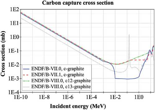
Apart from the ENDF/B-VII.1 continuous cross-section library, calculations have been performed with the ENDF/B-VII.0 and the ENDF/B-VIII.0 continuous cross-section libraries. Moreover, specific carbon and graphite cross sections have also been tested in different continuous ENDF/B cross-section library use cases. For the same base model, large keff discrepancies (about 1000 pcm) were observed by using different cross-section libraries, as shown in . Using the ENDF/B-VII.0 cross-section library for a model in a critical configuration with the ENDF/B-VII.1 library increased keff by about 1023 pcm. Oppositely, using the ENDF/B-VII.1 library for a model in a critical configuration with the ENDF/B-VII.0 library decreased keff by about 993 pcm. The discrepancies are mostly due to the carbon capture cross-section update between the two versions of the library. The discrepancies between ENDF/B-VII.0 and ENDF/B-VII.1 have been observed in previous studies by Bostelmann et al.:
For graphite-moderated systems such as pebbled-bed HTGRs, the capture cross section of carbon was significantly changed between ENDF/B-VII.0 and VII.1. Due to the abundance of graphite in this reactor concept in the fuel material and the reflector, a change in a cross section of carbon is highly relevant. Depending on the size of the simulated reactor model, an impact of more than 1,000 pcm on the multiplication factor can be observed. The ENDF/B-VII.1 calculation thereby show good agreement with measurements, while ENDF/B-VII.0 calculations show a significant overestimation.Citation13
TABLE V Nuclear Data Caused Discrepancies on keff and Change to Critical Core Configuration
To prove that the keff discrepancies between the ENDF/B-VII.1 and ENDF/B-VII.0 libraries are mainly due to the carbon cross section, manual changes were made to the cross-section libraries. A first test was to use the ENDF/B-VII.1 library, replacing only the c-graphite cross section with the ENDF/B-VII.0 c-graphite cross section. The opposite was also tested by using the ENDF/B-VII.0 library, replacing only the c-graphite cross section with the ENDF/B-VII.1 c-graphite cross section. The results of these tests are shown in . As expected, using the ENDF/B-VII.0 library with the ENDF/B-VII.1 c-graphite cross section is practically the same as using the regular ENDF/B-VII.1 cross-section library, with an obtained keff differing by only about 5 pcm. Similarly, using the ENDF/B-VII.1 cross-section library with the ENDF/B-VII.0 c-graphite cross section is practically the same as using the regular ENDF/B-VII.0 cross-section library, with an obtained keff differing by only about 8 pcm. These tests show how the major the update in the carbon cross section was implemented between the ENDF/B-VII.0 and ENDF/B-VII.1 versions.
TABLE VI Nuclear Data–Caused Discrepancies on keff with a Calculation Statistical Uncertainty of 10 pcm
Finally, the latest release of the ENDF/B-VIII.0 cross-section library was tested. The results are also shown in . All the results shown using the ENDF/B-VIII.0 cross-section library include the use of the latest thermal scattering law (TSL) data for graphite.Citation25 Using the regular ENDF/B-VIII.0 cross-section library and the crystalline graphite TSL, keff increased by about 320 pcm compared to the ENDF/B-VII.1 library.
An update in ENDF/B-VIII.0 for the c-graphite cross section is the ability to choose the porosity of the graphite. Graphite porosity is an essential parameter that can massively change the scattering properties, and it is still the object of current benchmarks efforts.Citation26 The regular ENDF/B-VIII.0 cross-section library uses nuclear data from a perfect crystalline graphite lattice with 0% porosity. shows that keff is sensitive to the graphite porosity, with increases of about 440 pcm for the 10% porosity and 640 pcm for the 30% porosity compared to the 0% porosity or pure crystalline case. According to the material definition found in the ICSBEP handbook for the HTR-10 benchmark, the porosity of the different graphite elements of the reactor (dummy and fuel pebbles, reflector) is between 20% and 30% (CitationRef. 20). In the HST, the porosity of the graphite used is estimated to be around 25%. Considering a linear impact of the porosity on keff between 10% and 30%, the keff for the HST with the evaluated porosity of 25% can be approximated to be around 1.00837 by doing a linear interpolation.
Using these results, the thickness of the graphite reflector used in the HST to reach a critical configuration can be reduced by about 20 cm. The total HST dimensions for a critical configuration were around 240 × 182 × 220 cm when using the ENDF/B-VIII.0 cross-section library and the derived 25% porosity graphite TSL data. These dimensions are similar to the critical configuration determined by using the ENDF/B-VII.0 cross-section library described in . The different evaluated carbon capture cross sections found in the ENDF/B-VII.0, ENDF/B-VII.1, and ENDF/B-VIII.0 libraries are shown in (CitationRef. 13).
Fig. 13. Comparison of c-graphite capture cross sections in different ENDF/B library releases.Citation13
These various observations show that the nuclear data currently used are still not perfect, and the designed concept would be beneficial for improving them. It should be mentioned that nuclear data uncertainties are not the only possible source of uncertainty in the HST critical experiments, for example, fuel and nonfuel impurities, such as boron in the graphite, density and porosity of graphite, hydrogen contents. Before any experiment is conducted on the HST, all materials used must be thoroughly characterized (material composition and dimensions).
IV.C.3. HST Concept Assessment of Mechanical Tolerances
The experimental uncertainties in keff associated with the mechanical tolerances were evaluated as discussed in Sec. III.C. The results of the sensitivity calculations for each of the mechanical tolerances are presented in , along with quadradic fits to the data. The fits were used to determine the mechanical tolerances that would result in experimental uncertainties ranging from 0.00010 to 0.00200 Δkeff, as shown in . A 200 pcm difference in keff would arise from a 0.308-cm horizontal gap, a 14.45-cm vertical gap, a 0.191-deg angular gap, and a 6.78-deg torsional offset.
TABLE VII Interpolated Geometric Uncertainties Necessary to Yield Experimental Uncertainties in keff of 5 to 200 pcm for the PBMR HST Experimental Concept
Fig. 14. Mechanical uncertainty influence on keff from calculation results and quadratic fits for the (a) horizontal, (b) vertical, (c) angular, and (d) torsional gap cases.Citation5
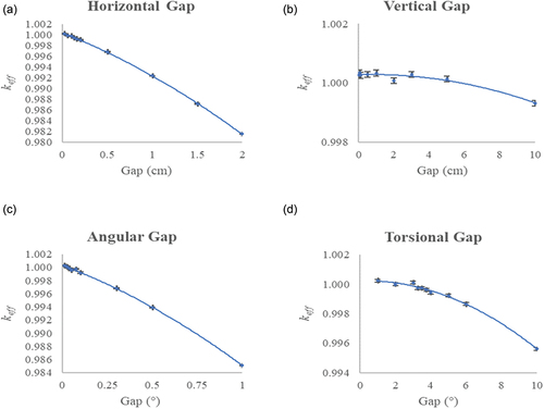
To achieve the goal keff uncertainty of about 5 pcm described in the HST specifications,Citation4 a vertical gap uncertainty under 4.5 cm would be necessary, as well as a horizontal gap uncertainty under 0.03 cm, an angular gap uncertainty under 0.0185 deg, and a torsional offset uncertainty under 1.8 deg. From these results, it appears relatively simple to avoid any significant keff uncertainties due to vertical gap and torsional offset. Still, the HST design is more sensitive to uncertainties in the horizontal and angular gaps. These differences can be easily explained. In the case of vertical and torsional offset uncertainties, most of the active regions of the two sides of the tables are still in contact, so the neutronic properties of the system are not significantly modified from significant contributions. Contrary to the case of horizontal and angular uncertainties, the two sides of the tables are apart, creating an air region that changes the neutron transport in the system, effecting a significant keff change for a relatively low mechanical tolerance uncertainty.
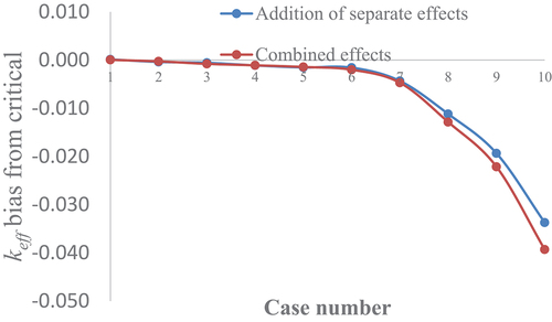
Of the four configurations tested, the two most significant mechanical tolerance contributions to keff were from the horizontal and angular gaps. A comparison of the simultaneous perturbations on the same split-table model and the added separate effects influence on the nominal keff is shown in , with a description of the cases studied given in . The combined effects had a similar influence on keff compared to adding the separate effects below the 0.5-cm horizontal and 0.1-deg gaps. On larger gaps, corresponding to case 8 and above, the combined effects had a greater influence on keff compared to the addition of the separate effects, with an approximately 600 pcm difference for the 2-cm horizontal and 1-deg angular gaps, for example. The identified combined effects’ increased influence on keff are not worrying for the future operation of the HST with the pebble-bed-type design because, from the mechanical specifications of the table, uncertainties as large as 2 cm horizontal and 1 deg angular are not expected.
TABLE VIII Description of the Different Cases Corresponding to the Simultaneous Horizontal and Angular Gap Perturbations
Fig. 15. Comparison of the keff bias from critical of the simultaneous horizontal and angular gap perturbations to the added separate effects.Citation5
V. DATA ASSIMILATION OF A HYPOTHETICAL EXPERIMENT
The optimized HST was used in a DA exercise to see how the integration of a hypothetical integral benchmark might improve predictions for a high-temperature, gas-cooled reactor. With sufficient resources, a mockup reactor is an ideal way to validate a potential reactor concept like the HTR-10. The mockup approach has limitations, especially in the very early stages of design where there may be no funding available to develop an experiment. There may also be no facilities or expertise to conduct mockup experiments. In these cases of insufficient experimental evidence, DA with a critical benchmark using a HST can be used to help improve predictions for a reactor design. Applying DA leads to increased confidence in an application’s model predictions despite being unable to explicitly validate said model with a mockup core. This idea is often called bias correction in the literature. Such analyses were traditionally done in neutronics to design fast reactors.Citation27–32 At that time, and to some extent still today, the nuclear data related to fast reactors were poorly known. The bias correction feature of DA was used for the design of the fast reactors PHENIX and SUPERPHENIX in France.Citation33 They predicted the critical mass of SUPERPHENIX within 300 pcm, despite the large uncertainties arising from the nuclear data and model inaccuracies.
In this work, we applied the generalized linear least-squares (GLLS) method to perform DA. This approach can be derived via Bayes’ theory and a linearization of the simulated response to nuclear dataCitation27,Citation28 to give the posterior nuclear data’s mean values σ and their covariance matrix Mσ’, which are given in EquationEq. (1)(1)
(1) and Equation(2)
(2)
(2) , respectively:
and
The posterior nuclear data must be calculated with the systems’ sensitivity profiles S, the experimental uncertainty covariance matrix ME, the experimental integral parameters E, and the calculated value of the integral parameter with the nuclear data C(σ). The posterior nuclear data are then used in EquationEqs. (3)(3)
(3) and (Equation4
(4)
(4) ) to calculate the posterior calculated value of the integral parameter C’ and the covariance matrix of the posterior integral parameter U’:
and
In this work, we took the sensitivity profile from the optimized HST and used it in EquationEqs. (1)(1)
(1) through (Equation4
(4)
(4) ) to adjust the ENDF/B-VII.1 nuclear data (multigroup mean values and covariances) and the simulated mean and uncertainty of the HTR-10, with C’ the adjusted keff and U’ the adjusted uncertainty matrix. The SCALE 44-energy-group structure was used in these analyses. NJOY21 (CitationRef. 34) processed the ENDF covariance data into this energy group structure. We assumed that this hypothetical HST reached criticality, making E = 1.0. For an adjustment to occur to the nuclear data, a bias must exist. To create a bias, we chose an arbitrary value for C of 1.01000. We also assumed that the experimental uncertainty was 150 pcm. As the experiment has not yet been performed, it is impossible to know the real keff and experimental uncertainty values, so the arbitrary values chosen for C and the experimental uncertainty could be modified.
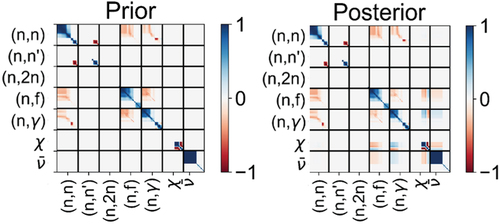
provides the relative change in the nuclear data mean values for a few selected nuclide/reaction pairs. Given the assumed bias in the HST simulation, it is clear that an adjustment to the nuclear data will be made. shows a significant adjustment for several nuclides and reactions, as well as a reduction in their standard deviation. provides a prior and posterior correlation matrix for 235U. In the posterior correlation matrix, there are new negative-valued terms, especially between fission (n,f), radiative capture (n,γ), prompt neutron multiplicity , and the fission spectrum
.
Fig. 16. Adjustments to nuclear data from using the GLLS method with the HST sensitivity profiles. Shown are the prior and posterior relative standard deviation of the multigroup cross sections and the relative adjustment of the multigroup mean values.
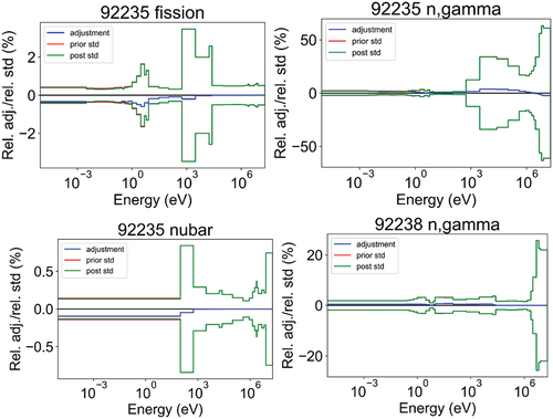
Fig. 17. Prior and posterior nuclear data covariance matrices of 235U.
The posterior nuclear data covariance matrix created a change in the uncertainty in the simulated keff values for each system. In the prior, the HST had 421 pcm uncertainty and the HTR10 had 394 pcm uncertainty. After adjustment of the covariance data, the keff uncertainties reduced to 141 pcm and 135 pcm, respectively. Finally, the adjusted nuclear data caused a change in the calculated keff value for each system, as calculated with EquationEq. (3)(3)
(3) . The keff of the HST changed from 1.01000 to 1.00111 after adjustment. The HTR10 keff changed from 1.00420 to 0.99592.
VI. CONCLUSIONS
To fill an identified gap in the critical experiments supporting the current designs of advanced reactors by various organizations around the world, a mechanical conceptual design for a HST was created. Using the specified HST dimensions, a reproducible methodology was devised to test different conceptual designs of benchmark critical experiments for advanced reactor nuclear data testing and validation.
The first advanced reactor type explored was the pebble-bed, high-temperature, gas-cooled reactor based on the previously characterized HTR-10 reactor. Design calculations were performed using different modules of SCALE and the ENDF/B-VII.1 cross-section library. A critical configuration was determined (keff = 0.99928 ± 10 pcm) matching the required machine dimensions, thus proving the conceptual feasibility of the design. The very high correlation between the HST design and the HTR-10 application case (ck = 0.9982) proved that the developed design was similar to the application. Performing such critical experiments would support the nuclear data testing, validation, and assimilationCitation35 necessary for any project to build similar reactors. After observing the significant influence of graphite on the criticality of the experiment, it was concluded that carbon cross-section data must be thoroughly examined. Another proof of the usefulness of this HST critical experiment was shown by performing DA of the hypothetical experiment. The DA analysis showed that both the HST concept and the HTR-10 application uncertainties could be reduced by several hundred pcm.
Current ongoing work includes a molten salt reactor as a second advanced reactor design with the MSRE as the basis, already modeled with SCALE.Citation36 A process similar to that used for the pebble-bed-type concept is being followed, with a goal of determining the feasibility of a HST design corresponding to this advanced reactor type on which nuclear data are to be focused. Other advanced reactor types, such as heat pipe reactorsCitation37 or space reactors similar to KRUSTY,Citation38 may also be explored.
The implementation of critical experiments on the proposed HST can be seen as the first step of validation for advanced reactor designs by using the similarity coefficient ck methodology. The HST should be used to validate cold-critical setup before creating a first reactor prototype. The HST could also be helpful for other matters related to advanced reactor design and operation, such as reactivity coefficient measurements, fuel preparation/handling (TRISO manipulation, pebble packing fraction, fuel salt handling), or criticality safety training for operators of these future advanced reactors. Nevertheless, other important reactor physics components cannot be validated by the HST experiments described in this work, and more advanced reactor prototypes should be used for this matter. Finally, the possibility of implementing this designed HST to perform critical experiments was heavily discussed during the National Criticality Experiments Research Center (NCERC) Futures Workshop in September 2022 (CitationRef. 39). The experts invited to the workshop agreed that it would be interesting for the community to have the HST capabilities at NCERC.
Acknowledgments
This work was supported by the Nuclear Criticality Safety Program, funded and managed by the National Nuclear Security Administration for the DOE.
This paper has been authored by UT-Battelle LLC, under contract DE-AC05-00OR22725 with the DOE. The U.S. government retains and the publisher, by accepting the paper for publication, acknowledges that the U.S. government retains a nonexclusive, paid-up, irrevocable, worldwide license to publish or reproduce the published form of this paper, or allow others to do so, for U.S. government purposes. DOE will provide public access to these results of federally sponsored research in accordance with the DOE Public Access Plan (http://energy.gov/downloads/doe-public-access-plan).
Disclosure Statement
No potential conflict of interest was reported by the authors.
References
- “Advanced Nuclear Reactor Technology, a Primer,” Nuclear Innovation Alliance (2022), https://nuclearinnovationalliance.org/sites/default/files/2022-07/ANRT-APrimer-July2022.pdf (current as of Oct. 26, 2022).
- “Mission and Vision FY2019-FY2028, The Mission and Vision of the United States Department of Energy Nuclear Criticality Safety Program,” Nuclear Criticality Safety Program, National Nuclear Security Administration, U.S. Department of Energy (2019), https://ncsp.llnl.gov/sites/ncsp/files/2021-04/ncsp_mission_vision.pdf (current as of Oct. 26, 2022).
- “International Handbook of Evaluated Criticality Safety Benchmark Experiments,” NEA 7497, Organisation for Economic Co-operation and Development (2019).
- C. PERCHER et al., “IER-539 CED-1: Preliminary Design of a New Horizonal Split Table,” LLNL-TR-827933, Lawrence Livermore National Laboratory (2021), https://www.osti.gov/servlets/purl/1825856 (current as of Oct. 26, 2022).
- M. N. DUPONT et al., “Horizontal Split Table Conceptual Design for Advanced Reactor Validation,” Proc. Int. Conf. on Physics of Reactors 2022, Pittsburgh, Pennsylvania, May 15–20, 2022, American Nuclear Society (2022).
- R. SANCHEZ et al., “A New Era of Nuclear Criticality Experiments: The First 10 Years of Planet Operations at NCERC,” Nucl. Sci. Eng., 195, S1 (2021); https://doi.org/10.1080/00295639.2021.1951077.
- W. KATO, G. FISCHER, and L. R. DATES, “Safety Analysis Report Argonne Fast Critical Facility ZPR-6,” ANL-6271, Argonne National Laboratory (1963).
- E. ROHRER, W. TUNNELL, and D. MAGNUSON, “Neutron Physics Division Annual Progress Report for Period Ending September 1, 1961,” ORNL-3193, Oak Ridge National Laboratory (1961).
- A. WILLIAMS et al., “Critical Assembly Machine for Plutonium Experiments,” UCRL-70343, Lawrence Livermore National Laboratory (1967).
- A. D. MILLER and G. HARMS, “Integral Experiment Request 226 CED-1 Summary Report Horizontal Split-Table Critical Assembly Conceptual Design for Sandia Experiments,” SAND2013-10178P, Sandia National Laboratories (2013).
- “SCALE Code System,” W. A. WIESELQUIST, R. A. LEFEBVRE, and M. A. JESSEE, Eds., ORNL/TM-2005/39, Version 6.2.4, Oak Ridge National Laboratory (2020).
- M. B. CHADWICK et al., “ENDF/B-VII.1: Nuclear Data for Science and Technology: Cross Sections, Covariances, Fission Product Yields and Decay Data,” Nucl. Data Sheets, 112, 12, 2887 (2011).
- F. BOSTELMANN, G. ILAS, and W. A. WIESELQUIST, “Key Nuclear Data Impacting Reactivity in Advanced Reactors,” ORNL/TM-2020/1557, Oak Ridge National Laboratory (2020).
- M. N. DUPONT et al., “Integral Experiment Request 554 CED-1 Summary Report,” ORNL/TM-2022/2682, Oak Ridge National Laboratory (2022).
- J. M. SCAGLIONE et al., “An Approach for Validating Actinide and Fission Product Burnup Credit Criticality Safety Analyses-Criticality (keff) Predictions,” NUREG/CR-7109 (ORNL/TM-2011/514), U.S. Nuclear Regulatory Commission (2012).
- B. T. REARDEN et al., “Sensitivity and Uncertainty Analysis Capabilities and Data in SCALE,” Nucl. Technol., 174, 236 (2010); https://doi.org/10.13182/NT174-236.
- G. ILAS et al., “Validation of SCALE for High Temperature Gas-Cooled Reactor Analysis,” NUREG/CR-7107 (ORNL/TM-2011/161), U.S. Nuclear Regulatory Commission (2012).
- M. B. CHADWICK et al., “ENDF/B-VII.0: Next Generation Evaluated Nuclear Data Library for Nuclear Science and Technology,” Nucl. Data Sheets, 107, 12, 2931 (2006); https://doi.org/10.1016/j.nds.2006.11.001.
- D. BROWN et al., “ENDF/B-VIII.0: The 8th Major Release of the Nuclear Reaction Data Library with CIELO-Project Cross Sections, New Standards and Thermal Scattering Data,” Nucl. Data Sheets, 148, 1, 1 (2018).
- W. K. TERRY et al., “Evaluation of the Initial Critical Configuration of the HTR-10 Pebble-Bed Reactor, HTR10-GCR-RESR-001” International Handbook of Evaluated Criticality Safety Benchmark Experiments, NEA 7497, Organisation for Economic Co-operation and Development Nuclear Energy Agency (2019).
- International Handbook of Evaluated Reactor Physics Benchmark Experiments, NEA 7496, Organisation for Economic Co-operation and Development Nuclear Energy Agency (2019).
- N. N. PONOMAREV-STEPNOI et al., “Graphite Annular Core Assemblies with Spherical Fuel Elements Containing Coated UO2 Fuel Particles, ASTRA-GCR-EXP-001,” International Handbook of Evaluated Reactor Physics Benchmark Experiments, NEA 7496, Organisation for Economic Co-operation and Development Nuclear Energy Agency (2019).
- J. D. BESS et al., “HTR-PROTEUS Pebble Bed Experiment Program Cores 1, 1A, 2, and 3: Hexagonal Close Packing with a 1:2 Moderator-to-Fuel Pebble Ratio, PROTEUS-GCR-EXP-001,” International Handbook of Evaluated Reactor Physics Benchmark Experiments, NEA 7496, Organisation for Economic Co-operation and Development Nuclear Energy Agency (2019).
- J. D. BESS et al., “Evaluation of the Start-up Core Physics Tests at Japan’s High Temperature Engineering Test Reactor, HTTR-GCR-RESR-001,” International Handbook of Evaluated Reactor Physics Benchmark Experiments, NEA 7496, Organisation for Economic Co-operation and Development Nuclear Energy Agency (2019).
- A. I. HAWARI and V. H. GILLETE, “Inelastic Thermal Neutron Scattering Cross Sections for Reactor-Grade Graphite,” Nucl. Data Sheets, 118, 176 (2014); https://doi.org/10.1016/j.nds.2014.04.030.
- N. C. FLEMING et al., “FLASSH 1.0: Thermal Scattering Law Evaluation and Cross Section Generation for Reactor Physics Applications,” Proc. Int. Conf. on Physics of Reactors 2022, Pittsburgh, Pennsylvania, May 15–20, 2022, American Nuclear Society (2022).
- H. MITANI and H. KUROI, “Adjustment of Group Cross Sections by Means of Integral Data, (I), (II),” J. Nucl. Sci. Technol., 9, 383, 642 (1972).
- J. B. DRAGT et al., “Methods of Adjustment and Error Evaluation of Neutron Capture Cross Sections; Application to Fission Product Nuclides,” Nucl. Sci. Eng., 62, 117 (1977); https://doi.org/10.13182/NSE77-3.
- A. PAZY et al., “The Role of Integral Data in Neutron Cross-Section Evaluation,” Nucl. Sci. Eng., 55, 280 (1974); https://doi.org/10.13182/NSE55-280.
- R. N. HWANG, “Topics in Data Adjustment Theory and Applications,” CONF-88091–28, Argonne National Laboratory (1988).
- A. GANDINI and PETILLI, “AMARA: A Code Using the Lagrange Multipliers Method for Nuclear Data Adjustment,” CNEN-RI/FI(73)39, Comitato Nazionale Energia Nucleare (1973).
- H. HÄGGBLOM, “Adjustment of Neutron Cross Section Data by a Least Square Fit of Calculated Quantities to Experimental Results. Part I Theory,” AE-422, Aktiebolaget Atomenergi, Studsvik, Sweden (1971).
- M. SALVATORES et al., “Methods and Issues for the Combined Use of Integral Experiments and Covariance Data: Results of a NEA International Collaborative Study,” Nucl. Data Sheets, 118, 38 (2014); https://doi.org/10.1016/j.nds.2014.04.005.
- J. L. CONLIN et al., “NJOY21: Next Generation Nuclear Data Processing Capabilities,” Eur. Phys. J. Conf., 146, 09040 (2017); https://doi.org/10.1051/epjconf/201714609040.
- G. PALMIOTTI, P. BLAISE, and F. MELLIER, “M. Salvatores: Integral Experiments and Their Use for the Validation of Nuclear Data and the Neutronic Design of Advanced Nuclear Systems,” EPJ Nucl. Sci. Technol., 7, 11 (2021); https://doi.org/10.1051/epjn/2021007.
- F. BOSTELMANN et al., “Modeling of the Molten Salt Experiment with SCALE,” Nucl. Technol., 208, 603 (2022); https://doi.org/10.1080/00295450.2021.1943122.
- E. WALKER et al., “SCALE Modeling of the Fast Spectrum Heat Pipe Reactor,” ORNL/TM-2021/2021, Oak Ridge National Laboratory (2021).
- D. I. POSTON et al., “KRUSTY Reactor Design,” Nucl. Technol., 206, 1, S13 (2020); https://doi.org/10.1080/00295450.2020.1725382.
- W. J. MARSHALL and M. N. DUPONT, “Critical Experiments in Support of Current Reactors and Advanced Reactor Deployment,” NCERC Futures Workshop, September 7–9, 2022, Los Alamos National Laboratory (2022).