
ABSTRACT
High layer thicknesses for laser powder bed fusion are promising for productivity increase. However, these are associated with increased process instability, spatter generation and powder degradation, crucial for alloys sensitive to oxygen. The effect of increasing layer thickness from 30 to 60 µm is studied focusing on Ti-6Al-4V spatter formation during LPBF and its characterisation, with scanning and transmission electron microscopy, combustion analysis and X-ray photoelectron spectroscopy. Results indicate that spatters are covered with a uniform Ti-Al-based oxide layer and Al-rich oxide particulates, the thickness of which is about twice that present on virgin powder. The oxygen content was about 60% higher in spatters compared to the virgin powder. The study highlights that increasing the layer thickness to 60 µm permits to reduce the total generation of spatters by ∼40%, while maintaining similar spatter characteristics and static tensile properties. Hence, this allows to increase build rate without compromising process robustness.
Highlights
Increased layer thickness from 30 to 60 µm resulted in ∼40% lower amount of spatter generated per build
Increased layer thickness from 30 to 60 µm resulted in ∼17% higher amount of generated spatter per scanned layer
Increase in bulk oxygen content by >60% was registered for spatter compared to the virgin powder in both cases
The oxide layer is about twice thicker on the spatter particles compared to virgin powder
1. Introduction
Spatters are byproducts of the laser powder bed fusion (LPBF) process originating from the instability of the melt pool and vaporisation effects induced by the laser scanning of the micrometre-sized metallic powder. Depending on the generation mechanisms, spatters can be distinguished between rather cold entrained particles and hotter spatter particles which have undergone partial to full re-melting or which are direct ejections from the melt pool [Citation1]. These spatters experience high temperatures during their formation leading to enhanced oxidation [Citation2]. As these tend to redeposit on the powder bed and be incorporated in the feedstock supply, spatters have been identified as a bottleneck for powder bed reusability, affecting sustainability of the technology [Citation3].
Ti–6Al–4V is particularly sensitive to the presence of residual oxygen in the LPBF process atmosphere because of the high affinity of Al and Ti for oxygen and the high temperatures associated with the laser-based additive manufacturing (AM). Despite being one of the most used alloys by the AM community, it was demonstrated only recently that accurate control of the processing atmosphere purity is necessary to limit oxygen pick-up [Citation4] and ensure consistent material properties during LPBF [Citation5]. Virgin Ti–6Al–4V powder is typically passivated by an homogeneous surface oxide layer of a few nanometres in thickness [Citation6]. However, very limited investigations of the surface oxide state of Ti–6Al–4V spatters have been conducted for LPBF. In the field of electron beam melting, Cao et al. [Citation7] studied Ti–6Al–4V powder degradation and highlighted that recycled powders exhibit Al loss at the surface connected to evaporation, as well as localised Al-rich oxidation explained by the high affinity of Al with oxygen, even under low vacuum of the process.
Recent studies have revealed that increasing layer thickness during LPBF leads to an amplified instability of the melt pool flow, mainly driven by the Marangoni flow and the recoil pressure. With high speed imaging of the process, Qiu et al. [Citation8] showed that the interaction of the laser with the powder bed led to more generation of incandescent spatters when the layer thickness was increased from 20 to 100 µm. In addition, their thermal fluid flow modelling allowed to explain these results considering a more important melt surface leading to an increased evaporation and Marangoni forces. Finally, the authors emphasised that the more important volume of particles exposed to the laser radiation also leads to more gas expansion in the region between powder particles, which contributes to the instabilities observed.
Results of several studies concord to the fact that increased layer thickness is usually at the expense of part dimensional accuracy, roughness and density [Citation8–10]. Still, Shi et al. [Citation11] demonstrated that Ti–6Al–4V parts with density above 99.9% can be achieved for layers of up to 200 µm with optimised beam properties and scanning parameters. With a more traditional and industrial system, Brika et al. [Citation12] compared the use of commercial laser parameters for 30 and 60 µm for Ti–6Al–4V and showed that resulting tensile properties were similar. Such an increase of layer thickness represents already an important reduction of scanned layers and thus of the overall built time. Therefore, increased layer thicknesses are promising to enhance the productivity of LPBF.
Limited effort has been put into studying the properties of the spatters resulting from the process instability for increased layer thicknesses. Such work is necessary to address if layer thickness increase is a sustainable approach to boost productivity, or if it will lead to premature degradation of the powder and hence increase the risk of defect formation and impair part quality. In the present study, analysis of Ti–6Al–4V spatters generated during builds with two different layer thicknesses, 30 and 60 µm, was conducted. Mechanical tensile testing of build samples completes the work and gives a full understanding of the effect of layer thickness increase for this material. Characterisation of spatter morphology by high resolution scanning and transmission electron microscopy, combined with combustion analysis for determination of impurity concentration and surface composition by means of X-ray photoelectron spectroscopy, bring new insights on properties of Ti–6Al–4V spatters and the effect of layer thickness.
2. Materials and methods
Virgin plasma atomised Ti–6Al–4V powder supplied by AP&C (GE Additive) was used as feedstock material. An EOS M290 (EOS GmbH) LPBF machine equipped with a Yb-fibre laser of 400W nominal maximum power and a building volume of 250 × 250 × 325 mm3 was employed. The powder feedstock particle size distribution measured by laser diffraction with a Mastersizer 3000 (Malvern Panalytical) was characterised by a D10 of 23 µm, D50 of 33 µm and D90 of 48 µm, average values obtained from 5 measurements. Standard laser parameters were used to process this powder with a 30 and 60 µm layer thickness under the respective user licenses Ti64_PerformanceM291 1.10 and Ti64_SpeedM291 1.10.
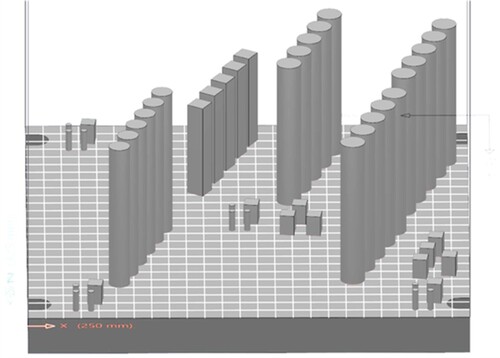
The build job was kept identical for the two layer thicknesses with a total built height of 86 mm, for a total built time of approximately 30 and 15 h for the 30 and 60 µm thicknesses, respectively. The present prints were performed under high purity Argon 5.0, with less than 10 ppm impurities. At the beginning of the build jobs, an O2 content around 1000 ppm was measured. The humidity was measured with a dewpoint sensor and was approximately −19°C for both prints. The builds consisted of several components, as presented in . Among these, three vertical tensile specimens of geometry according to ISO 6892-1 [Citation13] and a gauge section diameter of 5 mm were machined and tested for both builds, after a stress-relief heat treatment performed at 650°C for 3 h.
Figure 1. Layout of the conducted build jobs with 30 and 60 µm layer thicknesses in the EOS M290 machine.
After both build jobs were completed, spatters were carefully collected at different positions in the build chamber, namely, on top of the gas inlet, on top of the gas outlet and in the gas outlet. The gas inlet and outlet are the apertures placed symmetrically on both sides of the build area, through which the process gas recirculates. It has been shown in previous work [Citation1], that the deposits accumulating at these positions are consisting of process spatters, and are indicators of powder degradation during LPBF.
The collected samples were weighted with a high precision scale. The oxygen, nitrogen and hydrogen content of the virgin powder and samples were then measured by combustion analysis using a LECO ONH835. The built parts composition was measured for 3 samples at 5 positions on the baseplate for each build job and the average and standard deviation is given in the results section. Samples were also cut, mounted in resin, ground and polished for porosity measurement by light optical microscopy (LOM) with a ZEISS Axioscope 7. The production parameters optimised by the machine manufacturer yielded high density, above 99.9% for the 30 and 60 µm layer thicknesses. A field emission gun scanning electron microscope LEO Gemini 1550 (SEM) was used to analyse the morphology of the virgin powder and of the collected spatter particles.
The cross-section of selected spatter particles was made using a dual-beam FEI Versa 3D focused ion beam (FIB) milling system. The cross-section was lifted out following a conventional Transmission electron microscopy (TEM) lamella preparation method given in [Citation14] and was further thinned down to approximately 200 nm for investigations. The FEI TITAN 80–300 keV equipped with Oxford X-sight energy dispersive X-ray (EDX) detector was operated in a Scanning TEM (STEM) mode at 300 keV and investigations were performed on the FIB prepared thin lamella of spatter particle. The thin oxide scale was imaged using a high-angle angular dark field (HAADF) detector and analytical STEM-EDX investigations were performed to identify the chemical compositions.
Finally X-ray photoelectron spectroscopy (XPS) was conducted using ULVAC-PHI 5500 equipped with AlKα X-ray source. Powder samples for XPS analysis were mounted on 3M adhesive tape, and the dimensions of the analysis area were 300 × 300 μm2. To avoid the charging effect, continuous neutralisation of the sample with Ar+ ions was applied. Owing to the large measurement area, XPS results represent a statistical average of about 20–30 particles and therefore give a representative overview of the analysed powder sample. To estimate the oxide layer thickness, Ar+ ion etching was done with an etch rate of ∼5.2 nm/min. The etch rate was calibrated using TaO2 foil. The survey spectra and high-resolution narrow scans were acquired using a pass energy of 280 eV and 26 eV, respectively. The peak shift was adjusted carbon peak from advantageous hydrocarbons at 284.8 eV.
The tensile specimens were tested at room temperature according to the ISO 6892-1 standard [Citation13], on a Instron 5582 machine with a 100 kN load cell, at a constant strain rate of 2·10−3 s-1.
3. Results and discussions
3.1. Amount and morphology of generated spatters
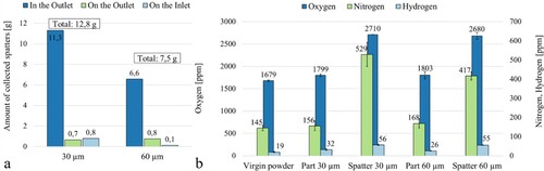
Spatters were collected on the gas inlet, on the gas outlet and inside the gas outlet for the build jobs completed with the two layer thicknesses, see (a). As depicted in a previous study focusing on Alloy 718 spatter characterisation [Citation1], a larger amount of spatters are collected inside the gas outlet. In addition, it appears that more spatters were collected and thus generated for the reduced layer thickness. This is expected to be related to the number of layers as powder bed was exposed to the laser scanning twice as many times at 30 µm layer thickness compared to 60 µm. From the total collected amount of spatters reported in (a), it is inferred that the higher layer thickness, i.e. combination of slightly higher energy input with higher amount of entrained particles, only resulted in an increase of about 17% of spatter generation by layer scanned.
Figure 2. (a) Amount of collected spatters for the 30 and 60 µm layer thickness build jobs. (b) Oxygen, nitrogen and hydrogen contents measured in the Ti–6Al–4V virgin powder, the built parts and in the spatter collected in the outlet after the 30 and 60 µm layer thickness build jobs. For interpretation of the references to colour in this figure, the reader is referred to the online version of this article.
The qualified laser parameters are in both cases a complex combination of so-called hatch, contour and edge parameters defining the pattern followed by the laser scan vectors, the laser power and speed followed to scan the build volume. Without revealing the intellectual property of the machine manufacturer developing these parameters, one can mention that the linear energy input, i.e. laser power divided by scanning speed, is about 15% higher for the 60 µm parameters compared to the 30 µm. Several in situ monitoring studies have highlighted the increase of spatter generation for increasing laser energy input. For example, Yin et al. [Citation15] demonstrated a gradual increase in the amount of spatter generated during processing of Inconel 718 with increasing laser power, which was associated with higher instability of the melt pool. In the present work, the increase of energy input from the 30 to 60 µm parameters is rather minor.
Brika et al. [Citation12] used the same process parameters for Ti–6Al–4V and layer thicknesses on a EOS M280 as employed currently, to study the powder bed densities for three powder lots produced by gas and plasma atomisation. They showed that regardless of the powder manufacturing route and exact composition, the powder beds achieved with the 60 µm layer thickness were always just slightly less dense than the 30 µm ones. For the 60 µm layer thickness, one can assume that about twice the volume of particles is exposed to the laser radiation compared to the 30 µm. It is thus suspected that more particles can be entrained by the vaporisation occurring close to the melt pool for the higher layer thickness.
Consistent with these findings, the work of Schwerz et al. [Citation16] on Hastelloy X processed on a EOS M290 equipped with Exposure OT monitoring system revealed that increasing layer thickness from 80 to 150 µm leads to a less efficient spatter removal and their redeposition affects a greater part of the manufacturing space. The extent to which these spatters redeposit on the powder bed and can overlap on the processing area of other components was also put in evidence using the Exposure OT monitoring of this machine for IN718® alloy and cellular structures [Citation17]. Another predominant factor to powder degradation during LPBF lifted by Chen et al. [Citation18], also thanks to OT monitoring, is the components design and in particular the surface-to-volume ratio as well as its orientation in the build space and the presence of large overhanging areas.
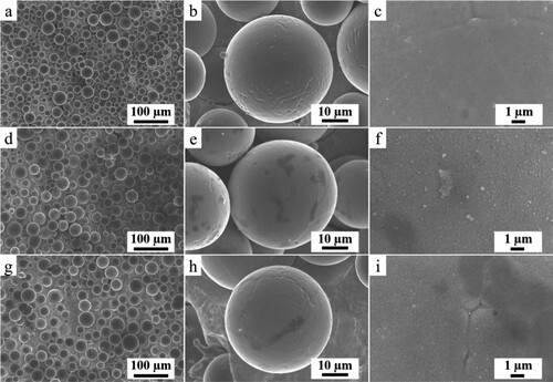
displays micrographs of the virgin Ti–6Al–4V powder employed and of the spatter collected in the gas outlet of the machine after the 30 and 60 µm build jobs. Oxide particulates with bright contrast can be distinguished on the surface of the collected spatters. Overall, the particle size distribution of the collected spatter samples is very similar to that of the feedstock powder, as can be seen from the low magnification images. This highlights that the mechanism by which these spatters are produced is rather unaffected by the change in laser parameters between the 30 and 60 µm sets. More importantly, the generated spatters that are depositing on the powder bed are likely to be retained in the process loop upon sieving and powder reloading in the machine.
Figure 3. Scanning electron micrographs of (a–c) the virgin Ti–6Al–4V powder used, (d–f) the collected spatter in the outlet following the 30 µm layer thickness build job, (g–i) the 60 µm one.
3.2. Composition of the parts and spatters
It is interesting to note that similarly as found in [Citation4, Citation5, Citation19], the oxygen content measured in the produced part is higher than that of the feedstock powder. Herein, a 7% increase of oxygen concentration from powder to part is recorded for both layer thicknesses. Likewise, an increase in the other impurities measured, namely nitrogen and hydrogen, is measured in the built parts compared to the powder. In terms of oxygen, nitrogen and hydrogen concentrations, the parts built with the 30 and 60 µm layer thickness are very similar.
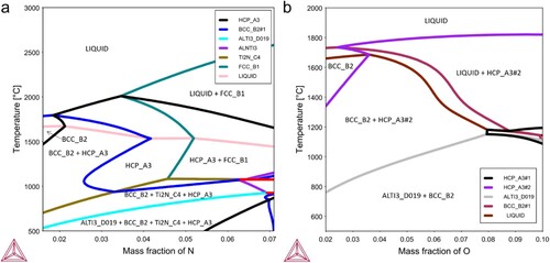
Regardless of the layer thickness, the collected spatter particles are characterised by a high oxygen and nitrogen content compared to the virgin powder used, see (b). An increase of about 60% of the oxygen content is measured for the spatters collected in the outlet compared to the virgin state. The nitrogen content is about 3 times higher in the spatter samples compared to the virgin powder. This important increase in oxygen and nitrogen pick-up is connected to the high oxygen and nitrogen affinities of the main alloying elements of the processed alloy, namely Ti and Al. Phase diagrams of Ti–6Al–4V with oxygen and nitrogen are simulated with the software Thermo-Calc 2021a using the TCTI2 database for Ti alloys v2.2. As depicted in , high solubilities of oxygen and nitrogen are predicted in comparison to the levels measured in the spatters, reaching up to about 4 wt.% of N and 5 wt.% of O at 1000°C. As the spatters are generated in the vicinity of the laser-powder bed interaction area, these are likely to experience high temperatures further enhancing the kinetics of oxidation, oxygen and nitrogen dissolution. From (b), it is also noted that the spatters collected with the higher layer thickness exhibit similar pick-up of oxygen and slightly less nitrogen impurities compared to the 30 µm ones.
Figure 4. Nitrogen and oxygen solubility in Ti–6Al–4V in dependence on the temperature, phase diagrams calculated with Thermo-Calc 2021a and the TCTI2 database for Ti-Alloys v2.2. For interpretation of the references to colour in this figure, the reader is referred to the online version of this article.
In the present work, similarly as for oxygen and nitrogen, the hydrogen content in the collected spatters increased compared to that of the virgin powder. The increase of hydrogen in the spatter samples may be connected to adsorption of moisture. The similar dewpoint of about -19°C measured for the process atmosphere of both prints is consistent with the identical hydrogen uptake by spatters.
3.3. Surface chemistry of the spatters
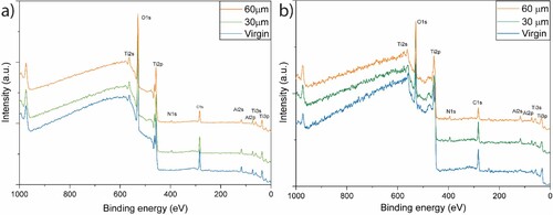
Changes in surface chemistry and nature of surface oxide layer from virgin to spatter powder particles are assessed by XPS analysis. A comparison of XPS survey spectra of virgin powder with samples collected from the gas outlet after the prints with 30 and 60 μm layer thicknesses are presented in the . (a) compares the spectra from as-received surfaces where distinctive peaks of titanium (Ti2p), oxygen (O1s) aluminium (Al2s) and carbon (C1s) can be observed. Compared to the virgin sample, an additional peak of nitrogen (N1s) can be observed on the as-received surface of spatter particles indicating nitrogen pick-up during spatter generation. In general, there is no significant difference in the surface composition of the top surface oxide layer between virgin and spatter powders, only slight difference in the peak intensities can be seen. The analysis of the survey spectra at 50 nm etched depth displayed in (b) shows that all previously mentioned peaks are persisting with slight variations in relative intensities. The Al2s peak for virgin powder disappeared at 50 nm etch depth. This highlights the surface enrichment in Al-oxide on the as-received surface of the virgin powder, and its disappearance after etching owing to a small thickness of this oxide. However, for spatter samples, the Al2s peak is still present at 50 nm etch depth, thereby indicating the presence of thicker Al-based oxide on spatters. Moreover, the N1s peak is also present at the depth of 50 nm for spatters. The appearance of the C1s peak at 50 nm etch depth is from the template tape used for sample preparation.
Figure 5. XPS survey scan of the virgin powder and of the spatters collected from the build jobs with 30 and 60 µm layer thickness at (a) as-received surface and (b) at 50 nm etched depth. For interpretation of the references to colour in this figure, the reader is referred to the online version of this article.
The XPS survey spectra do not allow to accurately estimate the difference in the intensity between the peaks of different elements from as-received to 50 nm etched surface. Therefore, depth profiles of individual elements using narrow scan over the binding energy of the elements of interest were used to evaluate the changes in the state of elements from oxides to metals. A comparison of depth profile of Ti2p, Al2p, and O1s from virgin powder ((a)) and spatter samples obtained from the build with layer thickness of 30 and 60 μm are shown in (b,c), respectively.
Figure 6. Depth profile comparison of Ti2p, Al2p and O1s narrow spectra of (a) virgin powder with spatters collected following the. (b) 30 μm and (c) 60 μm layer thickness build jobs. For interpretation of the references to colour in this figure, the reader is referred to the online version of this article.
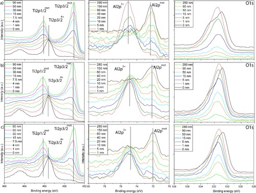
The peak position of the spectra were adjusted by using the internal XPS standards developed for Ti and its alloys presented in detail elsewhere [Citation6]. The Ti2p spectra obtained near the as-received surface shows the presence of Ti2p3/24+ peak at ∼459.15 eV, without distinguishable Ti2p3/2met peak. With etch depth, a metal peak of Ti2p3/2met appeared at ∼454.10 eV, and the Ti2p3/24+ peak merged with the Ti2p1/2met peak. The transition from the Ti2p3/24+ to the Ti2p3/2met peak was significant at 7.5 nm etched depth in the virgin sample, indicating that the oxide layer thickness in case of virgin powder is relatively small. However, for the spatter samples, this transition happened near the etched depth of 30 nm, highlighting the increase in Ti-based oxide layer thickness in spatters compared to virgin particles. It is important to note that number of particles are measured at the same time, meaning this increase is most probably connected to the presence of some heavily oxidised spatter particles, contributing to the total increase in the average oxide layer thickness, as described in detail in [Citation3]. Moreover, there was no significant change observed in the Ti2p spectra of spatters generated with different layer thicknesses, suggesting similar degradation mechanism, i.e. spatter type.
Additionally, the Al2p spectra are showing a comparable tendency to the Ti2p ones, with a coarsening of Al2p3+ oxide on spatter samples. At the 1 nm etched surface in virgin and spatter samples, Al2p3+ appeared at ∼74.80 eV, with a transition to Al2pmet peak with further etching of the samples. However, this transition was swifter for the virgin powder sample where oxide peak disappeared after ∼60 nm etching (on Ta2O5 calibration scale) compared to spatters where oxide peak disappeared only after ∼150 nm etching (on Ta2O5 calibration scale), owing to a lower oxide layer thickness on virgin particles. Another interesting aspect of the Al2p depth profile is the change in relative intensities. For example, near the surface, the virgin powder has a significantly higher intensity of the Al2p3+ peak which was absent at 60 nm etch depth where presence of solely Al2pmet peak was observed. However, the intensity of Al2pmet peak at this depth is substantially low, which increased with further etching. This could be connected to an Al depletion zone below the oxide layer, owing to Al diffusion towards the surface during powder solidification during atomisation. A similar trend can be seen in the Al spectra from the spatter powder samples. The presence of Al in the surface oxide layer of the powder particles can be expected from previous study by Hryha et al. [Citation6], where it was proposed that fine Al oxide precipitates (<50 nm) are expected to be present in the inter-dendritic areas on the Ti–6Al–4V powder surface.
For the O1s depth profiles, a slight variation in spectra from as-received to 1 nm etched surface is observed. This probably stems from the presence of absorbed water species on the as-received surface which was removed after slight etching. The change in the peak intensity with etched depth is an additional aspect which is linked to the thickness of the oxide layer. The intensity of the O1s peak dropped substantially at 50 nm etched depth in the virgin powder compared to spatter samples, reaffirming the presence of thicker oxide layer on spatter particles.
Considering the results shown in , it is important to estimate and compare the average oxide layer thickness of virgin and spatter powders, see (a). The average oxide layer thickness is estimated using normalised intensities of oxygen from the O1s spectra [Citation20, Citation21]. The determined oxide layer thicknesses are in the Ta2O5 thickness units which was used to determine the etch rate during depth profiling. However, as investigated by Baer et al.[Citation22], the etch rate of Ta2O5 is significantly higher than the etch rate of TiO2 and Al2O3 by a factor of ∼1.6, thus the actual values of oxide layer thickness will be substantially lower than the estimated values above. By readjusting the measured oxide layer thickness following the comparison done by Baer et al., the actual oxide layer thickness will be ∼7.5, ∼13.75 and ∼15 nm for the virgin powder, the 30 μm spatters, and the 60 μm spatters, respectively. Therefore, the oxide layer thickness of spatters obtained from two varying powder layer thicknesses are not particularly different.
Figure 7. (a) Oxide layer thickness estimation based on the O1s profile for the virgin powder, the spatter generated with the 30 and 60 µm layer thickness. The thickness measurement is relative to Ta2O5 and Al2O3 which were used as a standard to determine the etch rate. (b) High-angle annular dark-field (HAADF) image of the cross-section of a Ti–6Al–4V spatter particle; (c) STEM-EDX line scan profile in atomic %, the red dotted arrow shows the direction of the line scan. For interpretation of the references to colour in this figure, the reader is referred to the online version of this article.
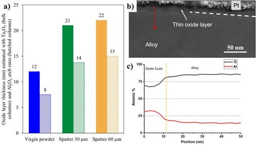
To get better understanding of the oxide layer thickness, distribution and homogeneity, TEM sample from the surface of spatter particles of the 30 µm build job was prepared using FIB technique. (b) shows a high-angle annular dark-field (HAADF) image of the thin lamella taken at a cross-section of the spatter particle close to the surface. The oxide scale enriched in both Ti and Al with a thickness of about 12 nm appears homogeneous with a dark contrast ((b)) and its chemical composition was confirmed using STEM-EDX point analysis and line scan ((c)). Despite the difficulty to analyse many particles in TEM, the performed measurement indicate that the thickness of the oxide layer is in the proximity to the estimation based on the O1s spectra of the XPS measurement.
3.4. Tensile properties
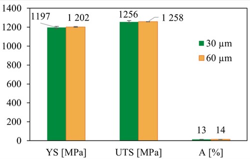
The tensile performances of the vertical machined specimens of the 60 µm layer thickness print appear similar to that of the 30 µm one, both with the UTS in the range of ∼1257 MPa, YS of ∼1200 MPa and elongation of about 13–14%, with a scatter in values less than 14 MPa for strength and 0.7% for elongation, see . This steady mechanical response is consistent with the comparable compositions measured in the bulk of the built specimens, see (b). The reported yield strength (YS), ultimate tensile strength (UTS) and elongation (A) are slightly superior to what reported by Dietrich et al.[Citation5] for samples printed with 30 µm thickness, powder from the same manufacturer (but different batch), the same machine (EOS M290) and the same stress-relief treatment (650°C/3 h). The YS and UTS are about 50 MPa higher and the elongation up to 6% improved. This could be owing to the different sample orientations, with horizontal specimens in the work of Dietrich et al. [Citation5], as expected from the material datasheet provided by the manufacturer [Citation23]. Further work will focus on the evaluation of dynamic response of similar samples. The work of Brika et al. [Citation12] suggests that depending on the powder atomisation process and PSD, increasing the layer thickness from 30 to 60 µm could have negligible to some impact on the surface roughness, which is mostly connected to the powder bed density. Still, the presented results on static properties are very promising for increasing the process productivity and regarding the steady spatter oxidation, for increasing process sustainability.
Figure 8. Tensile properties of stress-relieved samples built with standard laser parameters using a 30 and 60 µm layer thickness. For interpretation of the references to colour in this figure, the reader is referred to the online version of this article.
4. Conclusions
The present work highlights that increasing the layer thickness from 30 to 60 µm leads to lower amount of spatter generated by 40% for the total built height, despite a slight increase of generated spatters per scanned layer by ∼17%. In both cases, these spatter particles are characterised by higher oxygen content owing to the spatter oxidation and hence larger Ti-based oxide layer thickness, covering spatter particles, with additional enrichment in Al-rich oxide features observed on top. The thickness of the oxide layer is almost twice thicker than that present on the virgin powder. The analysis of spatter morphology and chemistry indicate the same characteristics of spatter particles and hence suggests that spatter generation process for the 30 and 60 µm layer thickness is the same. The bulk analysis of spatter composition revealed a dramatic increase of the oxygen by more than 1000 ppm (∼60%), and of the nitrogen by more than 200 ppm in comparison to the virgin powder. In addition, the spatter particles size being very similar to the virgin ones would directly be responsible for a conservation of these degraded particles within the processing chain and hence in the printed components, resulting in oxygen and nitrogen pick-up as well bringing risk for increased content of non-metallic inclusions. The measurement of oxygen, nitrogen and hydrogen impurities in the produced parts is very similar for both layer thicknesses and a 7% increase of oxygen from the feedstock powder composition is reported, highlighting the well-known sensitivity of Ti–6Al–4V to oxygen pick-up during LPBF processing from process atmosphere impurities and spatters. It is also important to note that the increase in layer thickness did not result in a change in static tensile properties with the UTS in the range of ∼1257 MPa, YS of ∼1200 MPa and elongation of about 13-14% with a low scatter in values for both layer thicknesses.
The present study suggests that the higher layer thickness is promising not only from the productivity standpoint but also having positive impact on powder reusability, with no paramount degradation of tensile properties, and thereby overall positive for the sustainability of LPBF processing of Ti–6Al–4V.
Acknowledgement
Special thanks are addressed to RISE Research Institutes of Sweden (Mölndal) for the particle size measurements with the Mastersizer 3000 (Malvern Panalytical).
Disclosure statement
No potential conflict of interest was reported by the author(s).
Additional information
Funding
Notes on contributors
Camille Pauzon
Camille Pauzon is a postdoctoral researcher at the SIMaP laboratory in Grenoble, which she joined after completing her PhD on process atmosphere for laser powder bed fusion at Chalmers University of Technology in 2021. Her research focuses on the processing and metallurgy of conventional and new alloys for laser powder bed fusion.
Ahmad Raza
Dr. Ahmad Raza is a CAM2 center researcher at the Chalmers University of Technology, specializing in powder bed fusion-based additive manufacturing processes. His research focuses on characterizing powders using advanced surface analysis tools such as X-ray photoelectron spectroscopy (XPS) and Auger electron spectroscopy (AES).
Imran Hanif
Imran Hanif's main research has been focused on the ex-situ and in-situ TEM and SEM investigations. He has been working on the advanced microstructural characterization of metallic materials/coatings, nanomaterials and energy materials. His recent publications are related to the high temperature corrosion of metallic materials and coatings.
Sophie Dubiez-Le Goff
Sophie Dubiez-Le Goff is an expert in Powder Metallurgy for Additive Manufacturing at Linde in Germany. She holds an PhD in Materials Science from MINES ParisTech.
Johan Moverare
Professor Johan Moverare's main research focus is the relationship between microstructure and mechanical properties, especially fatigue and creep properties of advanced metallic materials for demanding applications. His experience covers test methods, modelling aspects as well as characterization of deformation and failure mechanisms during fatigue. Many of the resent studies has been on additively manufactured metals.
Eduard Hryha
Professor Eduard Hryha is a researcher in powder metallurgy and metal additive manufacturing. His research focuses on powder metallurgy, powder-based metal additive manufacturing, surface analysis using advanced surface-sensitive techniques, as well as thermal analysis. He is also a director of CAM2 competence centre focusing on powder-based metal additive manufacturing.
References
- Pauzon C, Raza A, Hryha E, et al. Oxygen balance during laser powder bed fusion of Alloy 718. Mater Des. 2021;201; doi:10.1016/j.matdes.2021.109511.
- Raza A, Pauzon C, Hryha E, et al. Spatter oxidation during laser powder bed fusion of Alloy 718: dependence on oxygen content in the process atmosphere. Addit Manuf. 2021;48; doi:10.1016/j.addma.2021.102369.
- Raza A, Fiegl T, Hanif I, et al. Degradation of AlSi10Mg powder during laser based powder bed fusion processing. Mater Des. 2021;198:109358, doi:10.1016/j.matdes.2020.109358.
- Pauzon C, Dietrich K, Forêt P, et al. Control of residual oxygen of the process atmosphere during laser-powder bed fusion processing of Ti-6Al-4V. Addit Manuf. 2021;38; doi:10.1016/j.addma.2020.101765.
- Dietrich K, Diller J, Dubiez-le Goff S, et al. The influence of oxygen on the chemical composition and mechanical properties of Ti-6Al-4 V during laser powder bed fusion (L-PBF). Addit Manuf. 2020;32:100980. doi:10.1016/j.addma.2019.100980.
- Hryha E, Shvab R, Bram M, et al. Surface chemical state of Ti powders and its alloys : effect of storage conditions and alloy composition. Appl Surf Sci. 2016;388:294–303. doi:10.1016/j.apsusc.2016.01.046.
- Cao Y, Delin M, Kullenberg F, et al. Surface modification of Ti-6Al-4 V powder during recycling in EBM process. Surf Interface Anal. 2020;52:1066–1070. doi:10.1002/sia.6847.
- Qiu C, Panwisawas C, Ward M, et al. On the role of melt flow into the surface structure and porosity development during selective laser melting. Acta Mater. 2015;96:72–79. doi:10.1016/j.actamat.2015.06.004.
- Leicht A, Fischer M, Klement U, et al. Increasing the productivity of laser powder bed fusion for stainless steel 316L through increased layer thickness. J Mater Eng Perform. 2021;30:575–584. doi:10.1007/s11665-020-05334-3.
- de Formanoir C, Paggi U, Colebrants T, et al. Increasing the productivity of laser powder bed fusion: influence of the hull-bulk strategy on part quality, microstructure and mechanical performance of Ti-6Al-4 V. Addit. Manuf. 2020;33:101129, doi:10.1016/j.addma.2020.101129.
- Shi X, Ma S, Liu C, et al. Performance of high layer thickness in selective laser melting of Ti6Al4V. Materials (Basel). 2016;9:1–15. doi:10.3390/ma9120975.
- Brika SE, Letenneur M, Dion CA, et al. Influence of particle morphology and size distribution on the powder flowability and laser powder bed fusion manufacturability of Ti-6Al-4V alloy. Addit Manuf 2020;31:100929, doi:10.1016/j.addma.2019.100929.
- DIN EN ISO 6892-1:2016. - Metallic materials – Tensile testing – Part 1: Method of test at room temperature, 2017.
- Phother-Simon J, Hanif I, Liske J, et al. The influence of a KCl-rich environment on the corrosion attack of 304 L: 3D FIB/SEM and TEM investigations. Corros Sci. 2021;183:109315, doi:10.1016/j.corsci.2021.109315.
- Yin J, Yang LL, Yang X, et al. High-power laser-matter interaction during laser powder bed fusion. Addit Manuf. 2019;29:100778, doi:10.1016/j.addma.2019.100778.
- Schwerz C, Raza A, Lei X, et al. In-situ detection of redeposited spatter and its influence on the formation of internal flaws in laser powder bed fusion. Addit Manuf. 2021;47:102370, doi:10.1016/j.addma.2021.102370.
- Pauzon C, Mishurova T, Fischer M, et al. Impact of contour scanning and helium-rich process gas on performances of Alloy 718 lattices produced by laser powder bed fusion. Mater Des. 2022;215:110501, doi:10.1016/j.matdes.2022.110501.
- Chen Z, Raza A, Hryha E. Influence of part geometry on spatter formation in laser powder bed fusion of Inconel 718 alloy revealed by optical tomography. J Manuf Process. 2022;81:680–695. doi:10.1016/j.jmapro.2022.07.031.
- Pauzon C, Dietrich K, Forêt P, et al. Mitigating oxygen pick-up during laser powder bed fusion of Ti-6Al-4 V by limiting heat accumulation. Mater Lett. 2021;288:129365, doi:10.1016/j.matlet.2021.129365.
- Nyborg L, Nylund A, Olefjord I. Thickness determination of oxide layers on spherically-shaped metal powders by ESCA. Surf Interface Anal. 1988;12:110–114. doi:10.1002/sia.740120209.
- Oikonomou C, Nikas D, Hryha E, et al. Evaluation of the thickness and roughness of homogeneous surface layers on spherical and irregular powder particles. Surf Interface Anal. 2014;46:1028–1032. doi:10.1002/sia.5439.
- Baer DR, Engelhard MH, Lea AS, et al. Comparison of the sputter rates of oxide films relative to the sputter rate of SiO2, J Vac Sci technol A. 2010;28:1060–1072. doi:10.1116/1.3456123.
- EOS GmbH, Material data sheet EOS Titanium Ti64 Material data sheet Technical data, 49 (2014) 1–5.