
 ?Mathematical formulae have been encoded as MathML and are displayed in this HTML version using MathJax in order to improve their display. Uncheck the box to turn MathJax off. This feature requires Javascript. Click on a formula to zoom.
Abstract
This paper presents a feedback-feedforward steering controller that simultaneously maintains vehicle stability at the limits of handling while minimising lateral path tracking deviation. The design begins by considering the performance of a baseline controller with a lookahead feedback scheme and a feedforward algorithm based on a nonlinear vehicle handling diagram. While this initial design exhibits desirable stability properties at the limits of handling, the steady-state path deviation increases significantly at highway speeds. Results from both linear and nonlinear analyses indicate that lateral path tracking deviations are minimised when vehicle sideslip is held tangent to the desired path at all times. Analytical results show that directly incorporating this sideslip tangency condition into the steering feedback dramatically improves lateral path tracking, but at the expense of poor closed-loop stability margins. However, incorporating the desired sideslip behaviour into the feedforward loop creates a robust steering controller capable of accurate path tracking and oversteer correction at the physical limits of tyre friction. Experimental data collected from an Audi TTS test vehicle driving at the handling limits on a full length race circuit demonstrates the improved performance of the final controller design.
1. Introduction
Improvements in the cost and performance of real-time sensing and embedded computing have resulted in a proliferation of autonomous vehicle technology over the last two decades. A central control task in the operation of an autonomous vehicle is the ability to manoeuvre along a desired path, typically generated by a high-level path planner. As a result, a significant research effort has been devoted to the subject of active steering control for autonomous or semi-autonomous vehicles.
In particular, steering systems based on feedback-feedforward control architectures have been a major focus of research. Early work by Shladover et al. [Citation1] described a feedforward steering control law where the steady-state steering angle was determined from path curvature and longitudinal force inputs. The feedback steering algorithm was linear state feedback on lateral path deviation, heading deviation and their derivatives. The feedback gains were selected using a frequency shaped linear quadratic algorithm to minimise path tracking error while maintaining good ride quality at different frequencies. Nagai et al. [Citation2] also used linear quadratic regulation to design two feedback steering controllers for autonomous path following, with one controller using steer angle as the control input and the other using steering torque.
Another approach for implementing the feedback-feedforward control architecture is robust () control synthesis. Mammar and Koenig [Citation3] describe a driver-in-the-loop active handling system relying on results from robust control theory to minimise deviation from a desired trajectory. The steering feedback acts on the yaw rate error as opposed to path tracking error, and utilises a feedforward action that is a function of the driver steering command. An improved steering assistance system was later presented by Raharijaona et al. [Citation4] with an added torque input to improve stability margins.
Finally, a simple but effective approach to feedback-feedforward steering control is to design a controller with the objective of making the lateral tracking error zero at a certain ‘lookahead’ point in front of the vehicle. Minimisation of a lookahead objective was studied by Hingwe and Tomizuka,[Citation5] who proposed an input–output linearisation controller to achieve this objective. A crucial result from this study was the finding that internal yaw dynamics can be damped at all longitudinal velocities by making the lookahead point a quadratic function of the vehicle velocity. Rosseter [Citation6] also studied lookahead feedback systems extensively, and derived a similar controller by seeking to minimise a quadratic potential function of the projected lookahead error.
Regardless of the control strategy, ensuring passenger safety in emergency safety manoeuvres requires that autonomous steering systems achieve both stability and accurate tracking of a reference path at the physical limits of tyre adhesion. Autonomous path-following at the limits of handling has therefore become an actively explored topic of research. Kritiyikarana and Gerdes [Citation7] developed a steering controller on an Audi TTS with lookahead steering feedback and a feedforward approach based on tracking the vehicle center of percussion. This controller performed well at high levels of lateral acceleration (), but experienced significant vehicle oscillations near the limits of handling. In related work, Talvala et al. [Citation8] examined the Lyapunov stability of lookahead feedback at the limits of handling, and determined that desirable stability properties were maintained even in the presence of significant front and rear tyre saturation.
More recently, Filho and Wolf [Citation9] presented simulation results for a front-wheel steering controller based on dynamic model inversion. The resulting controller was able to track a reference oval path at the friction limits, and responded well to added curvature discontinuities. Carvalho et al. [Citation10] demonstrated a nonlinear model predictive controller capable of steering an experimental passenger sedan around obstacles at high speeds on an icy road. The controller was based on a nonlinear Ackermann model that was iteratively linearised. Yang et al. [Citation11] proposed a closed-loop quasi-linear optimal controller to reduce the post-collision lateral path deviation of a vehicle in a traffic accident. The robustness properties of the controller were demonstrated in simulation on a high-fidelity multi-body vehicle model. Finally, Sharp [Citation12] developed a linear optimal preview controller for motorcycle path tracking at the cornering limits. Gain scheduling according to speed and lateral acceleration enabled a range of linear controllers to be applied in different driving conditions.
This paper presents the design of a feedback-feedforward steering controller capable of combined stability and accurate path tracking at the limits of handling. A baseline controller with lookahead steering feedback and feedforward based on the nonlinear handling diagram is presented in Section 2. Section 3 uses steady-state simulation results to demonstrate the relatively poor path tracking performance of this baseline. In Section 4, the authors consider a modified steering feedback that aims to keep the vehicle sideslip tangent to the desired path, resulting in a closed-loop steering response with zero steady-state lateral path deviation, but at the cost of poor stability margins. A better design approach, presented in Section 5, is to incorporate the desired sideslip behaviour as a feedforward input, which significantly improves path tracking while maintaining robust stability margins. Section 6 provides experimental data collected on an Audi TTS test vehicle at Thunderhill Raceway in Willows, California, with combined lateral and longitudinal accelerations up to .
2. Controller architecture
A block diagram of a typical feedback-feedforward structure for steering control is shown in Figure . Inputs to the feedforward steering are the current path curvature κ and forward velocity
. Inputs to the feedback steering
are lateral path deviation e and path heading error
(Figure (b)). The total steering command δ is the sum of the feedback and feedforward inputs.
Figure 1. Block diagram of feedback-feedforward steering controller.
Figure 2. (a) Schematic of planar bicycle model (b) Projected error for feedforward steering calculation.
For the purposes of this work, the desired path curvature for the vehicle to follow is provided to the controller via a separate path planning algorithm.[Citation13] Additionally, the velocity profile is obtained from a longitudinal controller that keeps the combined vehicle acceleration magnitude at a specified value.[Citation7]
2.1. Feedforward steering design
The objective of the steering feedforward is to provide an estimate of the steer angle required to traverse a path with a known path curvature and velocity profile. This minimises the level of compensation required by the steering feedback, reducing tracking errors and allowing for less overall control effort. To simplify the controller structure, the feedforward steering angle should depend only on the desired trajectory and be independent of the actual vehicle states.
The proposed structure of the steering feedforward begins with the assumption that vehicle dynamics are given by the planar bicycle model, with relevant vehicle states and dimensions shown in Figure (a). This assumption allows the feedforward algorithm to account for the basic vehicle steering behaviour while leaving roll and weight transfer effects to be handled by the steering feedback.
The problem of determining suitable feedforward lateral tyre forces for autonomous path following was studied by Krisada and Gerdes.[Citation7] The (linearised) equations of motion for the states shown in Figure are given by
(1a)
(1a)
(1b)
(1b)
(1c)
(1c)
(1d)
(1d)
where m and
are the vehicle mass and out-of-plane rotational inertia, and s is the distance along the desired path. Taking time derivatives of
and
and substituting from
Equation (1a) and (1b) yields:
(2a)
(2a)
(2b)
(2b)
In general, the values chosen for the feedforward front and rear tyre forces
and
should bring
and
to zero. However, for a typical front-steer vehicle, direct control is only available for the front steering force
via command of the steering input δ. The rear tyre force depends indirectly on the front steering angle via the build-up of rear tyre slip
. It is therefore not possible to simultaneously eliminate both the lateral tracking error and heading angle error.
An alternative is to consider eliminating a weighted combination of the two error states by eliminating the lateral tracking error at a specified point
in front of the vehicle, as shown in Figure (b). The error dynamics at this projected point are given by
(3a)
(3a)
(3b)
(3b)
Kritayakirana and Gerdes [Citation7] proposed the centre of percussion as a convenient projection point for the feedforward steering. Substituting
and
yields a simplified equation for the front tyre force:
(4)
(4)
The benefit of choosing the center of percussion becomes clear in Equation (Equation4(3a)
(3a) ). The error dynamics at the centre of percussion are independent of the rear tyre force, which can be highly transient when the vehicle is cornering near the limits of handling. This leaves the only control input as
, which can be directly manipulated by the front wheel steering.
A feedforward steering approach based on eliminating tracking error at the centre of percussion performed well experimentally at high lateral accelerations up to .[Citation7] However, at higher lateral accelerations, the closed-loop steering response became underdamped, and the result was significant levels of yaw rate and steering wheel oscillation. This was due to the complex relationship between the desired feedforward front tyre force
and the required steering angle
needed to achieve that desired tyre force. In general, this relationship is dependent on the vehicle yaw rate r and sideslip β:
(5)
(5) where
is an inverse tyre model relating tyre force to tyre slip. Even though Equation (Equation4
(3a)
(3a) ) does not explicitly depend on rear tyre force, the feedforward steering command
implicitly depends on the transient rear tyre dynamics through the yaw rate and sideslip states. At the limits of handling, these transient dynamics become difficult to model.
To eliminate yaw rate oscillation, we propose simplifying the feedforward tyre forces by assuming steady-state cornering conditions. Setting ,
in Equation (Equation4
(3a)
(3a) ) and
in
Equation (1) yields the following front and rear tyre forces:
(6a)
(6a)
(6b)
(6b)
At steady-state conditions and assuming small angles, the feedforward steering angle of the vehicle relates to the front and rear lateral tyre slip and
and vehicle yaw rate r by vehicle kinematics:
(7)
(7) where
and
are the lumped front and rear feedforward tyre slip angles. The choice of feedforward tyre slip angles is related to the tyre forces in Equation (6) via the inverted tyre model
. To account for saturation of tyre force with increasing tyre slip magnitude, a single friction coefficient brush Fiala model [Citation14] maps lateral tyre slip angles into tyre force as follows:
(8)
(8) where μ is the surface coefficient of friction,
is the normal load, and
is the tyre cornering stiffness. These parameters are determined from experimental data taken from a ramp-steer manoeuvre, as shown in Figure .
Figure 3. Nonlinear tyre curves for FFW steering.
2.2. Feedback steering design
With the feedforward design complete, the remaining step is to design the feedback controller. The goal of the feedback controller is to minimise a ‘lookahead’ error
, which is the vehicle tracking error projected a distance
in front of the vehicle (Figure ).
Figure 4. Schematic of planar bicycle model showing projected lookahead error.
The lookahead error and resulting feedback control law are given by
(9a)
(9a)
(9b)
(9b) with proportional gain
. The control law (9) is a natural extension of potential field lanekeeping, as described by Rossetter et al. in [Citation6], which also provides heuristics for selecting
and
. Desirable stability properties over significant tyre saturation levels are demonstrated in [Citation8].
3. Predicted steady-state path tracking error
Simulation results provide useful insight about the steady-state path tracking behaviour of the baseline feedback-feedforward system. Linearised equations of motion for the vehicle and error states can be written in state-space form, with state variable x and control input δ defined as follows:
(10a)
(10a)
(10b)
(10b)
(10c)
(10c) where
is the vehicle understeer gradient. Note that
in (10a) depends on the state variable, and
depends on the path curvature. Rewriting the vehicle state equations of motion using curvature as the input results in:
(11a)
(11a)
(11b)
(11b)
(11c)
(11c)
where
and
and
are the lumped front and rear cornering stiffnesses. Figure shows results from using the linear model (11) to compute steady-state path tracking errors over a range of vehicle speeds, given a constant lateral acceleration of
3
. Additionally, steady-state results from the nonlinear feedforward control law (Equation7
(5)
(5) ) are plotted for the case where
. For this high lateral acceleration case, the equations of motion (1) and nonlinear Fiala tyre model (Equation8
(6a)
(6a) ) are used to predict the steady-state results. At low lateral accelerations, when the vehicle dynamics are dictated by linear equations of motion, the accumulated steady-state tracking error is small (< .05 m) at highway speeds. However, when steering at the limits of handling, Figure shows that the increased sideslip of the vehicle results in higher steady-state tracking error, creating challenges for accurate driving in safety-critical situations.
Figure 5. Steady-state path tracking error e, sideslip β and heading deviation as a function of vehicle speed. Results are plotted for the linear model, with fixed lateral acceleration
, and for the nonlinear model, with fixed lateral acceleration
.
A qualitative explanation for this steady-state error is shown in Figure (a). Since the steering controller acts to eliminate a weighted sum of heading error and lateral path deviation e, the lookahead feedback is successful in minimising the desired metric
at the projected distance
in front of the vehicle. However, this still allows for steady-state equilibria where values of e and
themselves are nonzero.
Figure 6. (a) Steady-state cornering where vehicle has lateral error but no lookahead error. (b) Zero steady-state lateral deviation requires vehicle velocity vector to be tangent to path.
4. Incorporating sideslip-path tangency into steering feedback
An interesting observation from Figure is that the steady-state path deviation is zero at a vehicle speed of around =20 m/s for the linear model and
=17 m/s for the nonlinear model. At these speeds, the steady-state vehicle sideslip is predicted to be zero as well, and the vehicle heading Ψ naturally becomes tangent to the desired path heading.
This observation motivates a second form of lookahead feedback where the feedback objective is to maintain the vehicle velocity vector U tangent to the desired path, as shown in Figure (b). Since , the resulting control law is
(12a)
(12a)
(12b)
(12b)
(12c)
(12c) where
is the heading of the desired vehicle path at a given point. The modified control law can be modelled by reformulating the matrix A in Equation (11) as
(13)
(13)
Note that Equation (Equation13(9b)
(9b) ) is equal to Equation (11b) with the exception of the last column. Figure shows the resulting steady-state behavior, and indicates that lateral error e settles to zero for all velocities.
Figure 7. Steady-state simulation results with sideslip added to feedback control, using the nonlinear vehicle model with fixed lateral acceleration of .
However, the disadvantage of directly adding vehicle sideslip into the feedback control is reduced stability margins. One method of observing the relative stability benefits of lookahead feedback is to draw a root locus plot of the closed-loop steering system pole locations as a function of vehicle speed. Closed-loop eigenvalues of Equations (11b) and (Equation13(9b)
(9b) ) are plotted in Figure as a function of increasing vehicle speed from 5 to 25 m/s. The results indicate that the closed-loop steering response is well-damped (
.9 at a vehicle speed of 25 m/s) with the original lookahead feedback controller. However, when, the steering feedback acts to keep the vehicle sideslip tangent to the desired path via Equation (12), the closed-loop steering response becomes highly underdamped (ζ = .2 at
).
Figure 8. Closed-loop pole locations for steering system as vehicle speed is varied from 5 to 25 m/s. Damping ratio ζ and natural frequency are shown for
= 25.
Note that the results shown in Figure are for a single vehicle and controller parameterisation (see Table ). In general, the reduction in stability margin will vary significantly depending on the vehicle understeer gradient and steering controller gains, namely the lookahead distance. Figure shows the critical speed , beyond which the closed-loop steering system becomes unstable, for neutral, understeering, and oversteering configurations as a function of
.
Figure 9. Maximum speed for closed-loop stability for the original lookahead feedback and the modified feedback with sideslip tracking. Results are based on eigenvalue computations of the A matrix of the linear vehicle model.
Table 1. Vehicle Parameters.
For an understeering vehicle, lookahead feedback is always stable as long as the lookahead point is above a certain critical value (a conclusion derived in [Citation6]). Even in situations where the vehicle is in a neutral steer or oversteer configuration, the critical speed for closed-loop stability increases rapidly with lookahead distance. A different trend is present when sideslip tracking is added to the steering feedback. Figure shows that the critical speeds for stability increase very slowly as a function of lookahead distance.
5. Incorporating sideslip information into steering feedforward
Given the trade-off between path tracking and stability when sideslip-path alignment is enforced via feedback, a promising approach is to replace vehicle sideslip β in Equation (12) with the predicted steady-state sideslip value for a given vehicle speed and curvature.
The rear tyre slip for a fixed track vehicle, assuming small angles, is given by
(14)
(14)
At steady-state, from Equation (Equation7
(5)
(5) ) and
, yielding the following feedback control law:
(15a)
(15a)
(15b)
(15b)
The effect of this change is to remove the steering controller's dependence on real-time sideslip information. The steering controller will now act to align the vehicle's predicted
steady-state sideslip along the desired path. Since the controller no longer has feedback on vehicle sideslip, the state matrix equation A for the closed-loop system dynamics is now once again given by Equation (11b), which was shown to have desirable stability properties as a function of and
(Figure ). The sideslip now affects the vehicle path tracking dynamics through the feedforward path, since the predicted steady-state sideslip
depends only on the desired speed
and curvature κ as well as the feedforward tyre model. The B matrix in Equation (11) now becomes:
(16a)
(16a)
(16b)
(16b)
Assuming perfect knowledge of the feedforward tyre model, the resulting steady-state lateral path deviation will be zero at all vehicle speeds, as shown in Figure . However, error in the feedforward tyre model will result in steady-state lateral path deviation. The effect of incorporating steady-state sideslip into the feedforward control is shown in Figure . The feedforward steering command as a function of path curvature and vehicle speed is plotted both for the original feedforward control law (11c) as well as the sideslip-incorporating feedforward command (16).
Figure 10. Effect of incorporating sideslip behavior into feedforward steering command , as a function of vehicle speed and desired path curvature.
6. Experimental results
6.1. Experimental set-up
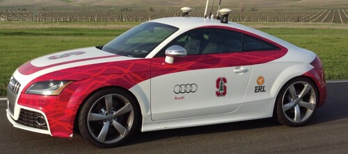
Experimental data were collected on an Audi TTS equipped with an electronic power steering motor for autonomous steering and active brake booster and throttle by wire for longitudinal control (Figure ). An integrated differential global positioning system and inertial measurement unit is used to obtain global vehicle states. A map-matching algorithm synthesises information from the GPS to determine the vehicle's position along the desired path and obtain the lateral path deviation e and vehicle heading error . The controller operates at 200 Hz. Vehicle parameters for the Audi test vehicle and the lookahead feedback gains are presented in Table .
Figure 11. Audi TTS used for experimental validation.
The site for data collection was a 3.1 mile paved racing circuit (friction coefficient ) at Thunderhill Raceway Park in Willows, CA. Figure shows an overhead view of the race track as well as the desired racing line. The desired racing line is parameterised as a curvature profile
that varies with distance along the path. The curvature profile associated with the racing line is shown in Figure along with a typical longitudinal velocity profile
from the path planner.[Citation13]
Figure 12. Overhead view of path planner output for steering controller to follow.
Figure 13. Curvature and velocity profile inputs for steering controller as a function of distance along racing line.
6.2. Experimental testing of sideslip feedback controller
The steering feedback controller with sideslip-path tangency presented in Section 4 offers very low path tracking error, but at the expense of reduced stability margins. To test this controller safely at the limits of handling, experimental data were collected on a constant radius turn in an open parking lot at two constant speeds. The results of this test are shown in Figure . As a baseline, the feedback controller with sideslip (12) from Section 4 is compared to the original lookahead feedback controller (9). The feedforward steering based on the nonlinear handling diagram (Equation7(5)
(5) ) is used in both cases.
Figure 14. Parking lot test for constant radius turning at 10 m/s and 13 m/s. Resulting steady-state accelerations are and
. Steering feedback with sideslip is compared to original lookahead steering controller.
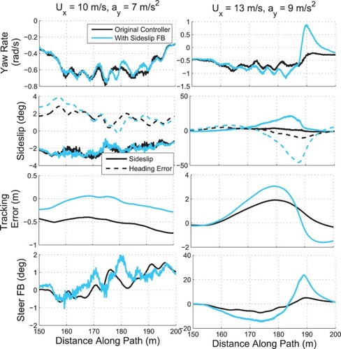
For the case where the speed is 10 m/s, the resulting steady-state acceleration is , and both steering controllers maintain stability of the vehicle. In addition, incorporating sideslip-path tangency into the feedback control law results in significantly lower path tracking errors compared with the baseline lookahead feedback controller. However, when the speed is increased to 13 m/s, the resulting steady-state lateral acceleration is
, and the sideslip feedback controller becomes unstable and goes into a spin, as demonstrated by the plots of yaw rate and sideslip. For the same conditions, the baseline lookahead controller remains stable. The issue with the sideslip feedback controller is shown in the plot of vehicle sideslip and heading error. As the vehicle heading error decreases and becomes unstable around
170 m, the feedback controller does not intervene because the vehicle's velocity vector remains tangent to the path (i.e.
0). A counter steering action is finally provided at
190 m, but at this point the vehicle has already spun out.
6.3. Experimental data from racetrack
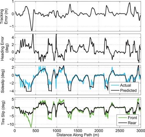
Figure shows experimental data taken over a 3 km subset of the entire racetrack, excluding portions of the course where there is little vehicle cornering. The experimental data are plotted for two separate steering controllers. The first controller is the ‘baseline’ controller described in Section 2, with the steering feedback provided by the lookahead system and the feedforward steering given by the steady-state handling diagram. The second controller uses the same lookahead feedback, but incorporates the steady-state sideslip behavior into the feedforward steering to align the vehicle's velocity vector with the path heading (Section 5). Note that the controller where real-time sideslip was incorporated into the steering feedback (Section 4) was not tested, as there is a high likelihood of vehicle instability near the limits of handling given the results from the previous parking lot test. The same longitudinal controller is used for both cases in order to brake into the entry of turns and accelerate out of turn exits. For this lap, the peak longitudinal deceleration is and peak lateral acceleration is
.
Figure 15. Experimental data with combined acceleration magnitude over 3 km stretch of Thunderhill Raceway Park.
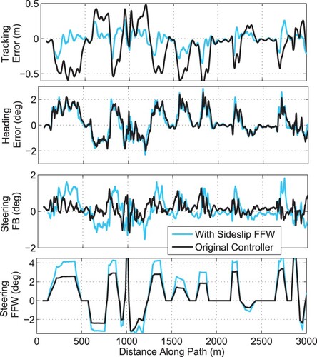
The results in Figure show that lateral path deviation e is reduced when incorporating steady-state sideslip in the feedforward control law. This confirms the expected results from the analysis performed in Sections 3 and 5. Note that while the lateral path deviation is smaller, the levels of vehicle heading error remain roughly the same. This matches the predicted result in Figure . The steering controller will align the vehicle's velocity vector with the path, not the vehicle's heading, and due to a vehicle's tendency to develop a steady-state sideslip angle, a non-zero heading error
is in general necessary for zero steady-state lateral path deviation, as shown by the schematic in Figure (b).
For a better sense of the improvement in lateral path deviation, Figure shows histogram plots of the lateral tracking error e for both controllers over three laps taken at varying levels of peak lateral acceleration. The baseline controller keeps the vehicle within 0.5 m on either side of the desired path, with a large amount of variation in the resulting histogram. An interesting observation is that the histogram is not symmetric. In general, the raceway has more left turns than right turns, and as Figure indicates, at high speeds the baseline controller will track toward the outside of the turn. This tendency is manifested experimentally in the asymmetric nature of the histograms. The histograms for the improved controller show a much tighter distribution on the lateral path tracking error. The path tracking error generally remains within 10–15 cm on either side of the lane boundary and contains less of a bias towards tracking on the outside of turns.
Figure 16. Histogram of path tracking error for six laps around the track. Left column represents performance of controller with feedforward sideslip tracking, and right column is baseline controller with feedforward from the steady-state handling diagram.
As the lateral acceleration increases beyond 0.8 g and the vehicle approaches the handling limits, the steering controller remains stable and well-damped, although the tracking performance begins to degrade. Figure shows experimental data for a lap around Thunderhill Raceway park with peak lateral and longitudinal accelerations of 0.95 g. At several points along the track, the tracking error increases above 0.5 m, significantly higher than the levels of path deviation seen at 0.8 g of vehicle acceleration. The reasons for this are three-fold.
Figure 17. Experimental data with combined acceleration magnitude over 3 km stretch of Thunderhill Raceway Park.
First, the sharp drop in front tyre slip from meters indicates that the lateral force demand for the front tyres has exceeded the available friction at that region of the track. As a result, the vehicle understeers heavily and tracks well to the outside of the left-hand turn, resulting in a large negative tracking error. At this point, there is nothing the steering controller can do to bring the vehicle back to the desired path, and the vehicle must alter its desired trajectory to become less aggressive, either by slowing down or reducing the turn curvature. Second, the steady-state feedforward controller requires an accurate estimate of the vehicle parameters in order to estimate the steady-state sideslip in Equation (15a). From
, 1300–1400, 1800–1900, and 2200–2300 meters along the track, there are observable discrepancies between the predicted feedforward sideslip and the actual vehicle sideslip, as measured by the GPS-INS. Not surprisingly, this plant-model mismatch results in significant path tracking errors at those portions of the racing circuit. Finally, the feedforward model in Equation (15a) assumes steady-state conditions. As the vehicle approaches the limits of handling, transient vehicle dynamics can result in larger path deviations as well.
Future work will focus on reducing the latter two sources of error by gradually learning a better feedforward model of the vehicle dynamics over time. For situations where a vehicle repeats a given trajectory multiple times, iterative learning control (ILC) is a promising technique for refining the feedforward input to improve the reference tracking performance of the controller. Additionally, online estimation approaches can also be used to gradually improve knowledge of difficult-to-measure parameters such as friction and vehicle cornering stiffness.
7. Conclusion
This paper describes the design of a feedback-feedforward controller capable of path tracking at the limits of handling. Desirable path tracking behavior occurs when the vehicle sideslip is aligned with the desired path heading. However, directly incorporating this behaviour into a feedback steering control law results in a closed-loop controller with poor stability margins. A better approach for combined path tracking and stability is to align the steady-state vehicle sideslip with the desired path heading through the feedforward steering command. This enables improved path tracking while maintaining the robust stability properties of lookahead steering feedback. Results from a histogram analysis quantitatively indicate that the improved feedforward command reduces lateral path deviation by more than 50%. One potential drawback is that this feedforward approach is sensitive to vehicle model uncertainty, especially at the physical limits of handling where transient dynamics become prevalent. Future work will seek to use methods such as iterative learning control or online parameter estimation to improve the feedforward vehicle model and eliminate undesirable transient dynamics.
Acknowledgments
The authors would like to thank Joe Funke, Paul Theodosis, Krisada Kritayakirana, John Kegelman, and Steve Erlien of the Dynamic Design Lab at Stanford University, as well as Rob Simpson and Rick Keiner of the Audi Electronics Research Lab.
Disclosure statement
No potential conflict of interest was reported by the authors.
Additional information
Funding
Related Research Data
References
- Shladover SE, Desoer CA, Hedrick JK, et al. Automated vehicle control developments in the path program. IEEE Trans Veh Technol. 1991;40(1):114–130. doi: 10.1109/25.69979
- Nagai M, Mouri H, Raksincharoensak P. Vehicle lane-tracking control with steering torque input. Veh Syst Dyn Suppl. 2002;37:267–278.
- Mammar S, Koenig D. Vehicle handling improvement by active steering. Veh Syst Dyn. 2002;38:211–242. doi: 10.1076/vesd.38.3.211.8288
- Raharijaona T, Duc G, Mammar S, Robust control and μ-analysis with application to lateral driving assistance. In: Proceedings of IEEE Intelligent Transportation Systems; Shangai; 2003. p. 247–252.
- Hingwe P, Tomizuka M, A variable look-ahead controller for lateral guidance of four wheeled vehicles. In: Proceedings of the American Control Conference; Philadelphia; 1998. p. 31–35.
- Rossetter EJ, A potential field framework for active vehicle lanekeeping assistance [dissertation]. Stanford, CA: Stanford University; 2003.
- Kritayakirana K, Gerdes JC. Using the center of percussion to design a steering control for an autonomous racecar. Veh Syst Dyn. 2012;50:33–51. doi: 10.1080/00423114.2012.672842
- Talvala KL, Gerdes JC, Lanekeeping at the limits of handling: Stability via Lyapunov functions and a comparison with stability control. In: Dynamic Systems and Control Conference; Ann Arbor; 2008. p. 361–368.
- Filho C, Wolf D, Dynamic inversion-based control for front wheel drive autonomous ground vehicles near the limits of handling. 2014 IEEE 17th International Conference on Intelligent Transportation Systems (ITSC), IEEE; Qingdao; 2014. p. 2138–2143.
- Carvalho A, Gao Y, Gray A, Tseng H, Borrelli F, Predictive control of an autonomous ground vehicle using an iterative linearization approach. 2013 16th International IEEE Conference on Intelligent Transportation Systems-(ITSC); The Hague; 2013. p. 2335–2340.
- Yang D, Jacobson B, Jonasson M, Gordon TJ. Closed–loop controller for post–impact vehicle dynamics using individual wheel braking and front axle steering. Int J Veh Auton Syst. 2014;12(2):158–179. doi: 10.1504/IJVAS.2014.060114
- Sharp RS. Rider control of a motorcycle near to its cornering limits. Veh Syst Dyn. 2012;50(8):1193–1208. doi: 10.1080/00423114.2011.607899
- Theodosis PA, Gerdes JC, Generating a racing line for an autonomous racecar using professional driving techniques. Dynamic Systems and Control Conference; Arlington; 2011. p. 853–860.
- Pacejka HB. Tire and vehicle dynamics. 3rd ed. Waltham, MA: Butterworth-Heinemann; 2012.