
 ?Mathematical formulae have been encoded as MathML and are displayed in this HTML version using MathJax in order to improve their display. Uncheck the box to turn MathJax off. This feature requires Javascript. Click on a formula to zoom.
Abstract
Force and moment measurement at different locations within road vehicles is a multifaceted, comprehensive and forthcoming technology that might play a breakthrough role in automotive engineering. The paper aims to describe why such technology seems so promising. A literature review is accomplished on which forces can be measured and what can be obtained with force and moment data. Additionally, attention is devoted to where – and how – force and moments can be measured effectively. Force and moment measurement technology is also studied with an historical perspective, briefly analysing the past applications. Active safety systems (ADAS up to full automated driving) and automotive stability enhancement systems are expected to be impacted by the measurement of forces and moments at the wheels. Friction potential evaluation and driver model development and monitoring have been – and are expected to be – major field of research. Force and moment measurement technology may also be exploited for lightweight construction purposes with remarkable synergistic effects with active safety and stability enhancement systems. Possible innovations on lightweight construction and sustainable mobility are to be expected thanks to force and moment measurement.
1. Introduction
The aim of this state-of-the-art paper is to report why, what and where forces and moments can be sensed within a road vehicle, in order to improve both active safety systems (e.g. ADAS) and stability enhancement systems (ABS, TCS and ESC, Figure ). New concepts for addressing lightweight construction are introduced. Attention is also devoted to the historical aspects on when forces and moments were sensed first. Who has contributed to the topic is obviously mentioned in the literature.
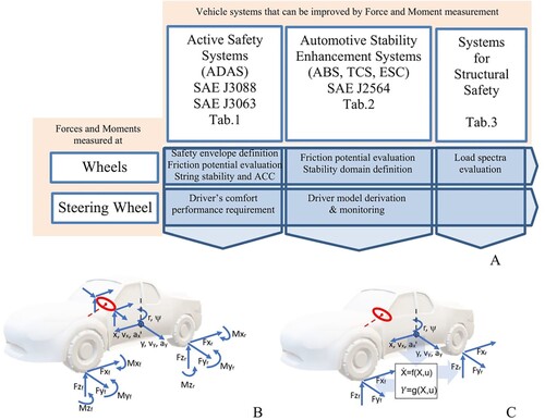
Figure 1. (A) Relevant research areas related to force and moment measurement technology: Safety envelope definition, friction potential evaluation, string stability and ACC, stability domain definition, load spectra evaluation, driver’s comfort and driver model derivation and monitoring. (B) Forces and moments relevant to be measured in a vehicle and kinematics variables typically controlled by the driver. (C) Sensing process of main acting forces at the tyres based on state estimation.
In the title of the paper, ‘force’ refers to generalized forces, i.e. forces and moments. We will refer in the paper to ‘force and moment measurement’ or to ‘forces and moments measurement’ in order to address the general set of the three components of a force and the three components of a moment acting on a body. Sometimes ‘torque’ will be used instead of ‘moment’ when lexicon suggests this wording.
For the sake of space, forces sensed by pneumatic tyres are not dealt with here. Actually, a dedicated paper would be required.
In [Citation1,Citation2], the force and moment sensors that are used in road vehicles are listed. The most relevant are (1) coupling force sensor between towing vehicle and trailer, (2) damping force sensor, (3) axle load sensor for commercial vehicles, (4) brake pedal force sensor, (5) brake force sensors, (6) driveline torque sensor, (7) wheel forces and (8) steering wheel or power steering torque sensor.
A first distinction is needed: Forces and moments may be needed to characterise the dynamic behaviour of
a single vehicle component (e.g. 2, 4, 5) or
a vehicle as a whole (e.g. 7) or a system within a vehicle (e.g. 1, 6, 8).
Usually,
in case (a) the force and moment measurement is performed in a laboratory or a test track;
in case (b) the measurement device(s) is (are) supposed to be placed in a vehicle for mass production, today or in the future.
We will focus particularly on the second case, and exclusively on 7 and 8 cases, namely wheel and steering wheel forces. The aim is to envisage possible future applications featuring a huge impact on the mobility of the future, namely on Cooperative, Connected and Automated Mobility [Citation3,Citation4].
We will investigate how force and moment measurement may impact on
automotive stability enhancement systems [Citation7]
lightweight construction.
Referring to active safety systems, two SAE standards are fundamental [Citation5,Citation6] as they deal respectively with active safety sensors and with active safety nomenclature. Noteworthy, in [Citation5], within the list of active safety sensors, no explicit mention is made to force and moment measurement. This might be due to the lack of envisaged applications of such sensors at the time the document was written.
Referring to automotive stability enhancement systems (ABS, Traction Control, Electronic Stability Control), we adopt the taxonomy indicated by SAE [Citation7].
Referring to lightweight construction, we will make a broad overview of existing practices and possibilities related to force and moment measurement.
Lightweight construction aims to reduce the mass of the vehicle as shown in [Citation1,Citation8]. All of the structures of a vehicle (namely, body, interiors, suspensions, wheels, brakes and so on) may be lighter if acting forces are known precisely, during the whole lifecycle. Making a structure as light as possible implies making it as weak as possible, thus structural safety is also an issue for lightweight construction. The definition of structural safety is given in [Citation9]. The force and moment sensors will be often used for structural health monitoring which is a branch of structural safety. Lightweight construction implies also sustainability [Citation1,Citation8] and noise-vibration-harshness performance [Citation1].
In [Citation10–12], the general definitions and activities are addressed to obtain the safety of the intended functionality for either an active safety system or a stability enhancement system. The model for describing how such systems have to work is composed by three phases, namely: sense, plan and act. Figure shows the model.
Figure 2. The three main phases pertaining to the model described by the ISO standard ‘Safety of the intended functionality’ [Citation10]. The model is adopted to develop L3 and L4 automated vehicles [Citation12]. Adapted from [Citation10,Citation11].
![Figure 2. The three main phases pertaining to the model described by the ISO standard ‘Safety of the intended functionality’ [Citation10]. The model is adopted to develop L3 and L4 automated vehicles [Citation12]. Adapted from [Citation10,Citation11].](/cms/asset/9e535662-9efc-4d26-ab23-ddd492552c2d/nvsd_a_2240447_f0002_oc.jpg)
The paper will focus mostly on sensing forces and moments to allow, later, the planning of actions and, subsequently, the actuation of controlled systems. Planning of actions and actuating controlled systems are not dealt with in detail in this paper. For a state of the art on these topics, the reader may refer to [Citation13,Citation14] where tyre–road friction evaluation and tyre force estimation are dealt with. For the sake of space, the estimation of vehicle states and slips, in either longitudinal or lateral direction is not addressed in-depth in this paper.
Accurate sensing has been addressed in [Citation15] as one of the needed activities to enhance the autonomous functions of road vehicles. This review paper is focused on force and moment measurement technology and covers the ‘sense’ block in Figure .
The paper is organised as follows. First, the reasons why force and moments should be measured to improve the active safety and lightweight construction of road vehicles are introduced. Then, what can be obtained by force and moment measurement is addressed. Then, the focus is on where forces and moments can be measured within the vehicle, taking into account just a limited but significant number of locations and sensors, namely suspensions and steering wheel. An historical section clarifies when force and moment measurement have started to attract attention by the automotive community. Finally, a discussion is presented and conclusions are drawn.
2. The importance of forces and moments to active safety, stability enhancement systems and lightweight construction – why sensing forces and moments?
2.1. Research areas, vehicle systems and vehicle components
Figure shows some relevant research areas that are – and could be in the future – heavily impacted by force and moment measurement technology. In [Citation16], a review on the safety of CAVs (connected automated vehicles) that matches with the research areas of Figure is reported.
In Figure (B), the main kinematics variables of a car which are the ones that the driver (human or not human) aims to control are shown. They typically are the position on the road of the vehicle and its body attitude, the speeds of the vehicle (longitudinal, lateral, yaw) and the accelerations of the vehicle (longitudinal, lateral). The forces and moments at the tyres that are needed to control the said kinematic variables are reported in Figure (B). The direct measurement of such forces and moments avoids to exploit digital twins of vehicle components (wheel, tyre, suspension, body, etc.) (Figure (C)). This makes quicker and more accurate the estimation, as it will be shown in the remaining part of the paper.
Table refers to the active safety systems listed in [Citation6] and defines in which case force and moment sensors could be effectively used. The rankings in Table cannot be commented on here but will be clarified through the text of the paper. Similar rankings were presented in [Citation17].
Table 1. Active safety systems listed in SAE J3063.
Table shows, according to SAE J2564, the automotive stability enhancement systems and defines in which case force and moment sensors could be effectively used for improving stability. As for Table , the rankings in Table cannot be commented on here but will be clarified through the text. Similar rankings were presented in [Citation17].
Table 2. Automotive stability enhancement systems listed in SAE J2564 [Citation7].
Table lists the main vehicle components and defines in which case force and moment sensors could be effectively used for improving lightweight construction.
Table 3. Vehicle components and impact on lightweight construction of force and moment data measured for active safety or for stability enhancement.
The force and moment measurement technology is relatively expensive. A way to limit the higher vehicle production costs may be based on the adoption of a lightweight construction strategy.
Lightweight construction affects structural safety negatively, the basic issues to cope with this problem are given in [Citation1,Citation8] and refer to excessive structural compliance, noise-vibration-harshness, buckling and mechanical fatigue or static resistance. It appears that a continuous monitoring of structural health may allow the adoption of lightweight structures. Such a continuous monitoring could be obtained by using force and moment measurement technology.
By using force and moment data at the same time for active safety issues, for stability enhancement issues and for lightweight construction issues, may facilitate the adoption of force and moment measurement technology. A positive synergistic effect can be obtained.
In the automotive sector, technologies that allow synergies are often welcome, as implicitly or explicitly addressed in [Citation61], referring to many different vehicle components.
2.2. Metrological aspects of forces and moments measurement technology
Referring to metrology theory and related vocabulary [Citation67–74], the measurement result, i.e. the value of a quantity, has to:
fulfil the conditions of acceptability, given the acceptable range of the measurement and the uncertainty of the measurement, such conditions are defined in Appendix 1.
be repeatable (closeness of the agreement between the results of successive measurements of the same measurement carried out under the same conditions of measurement).
be reproducible (closeness of the agreement between the results of measurements of the same measurements carried out under changed conditions of measurement).
Typically [Citation67], repeatability can be verified by performing many measurements in a short period of time, when external conditions are steady. Reproducibility refers to measurements taken in different time periods. Referring to vehicle force and moment measurements, reproducibility involves changes in temperature, humidity, road conditions, vehicle speed, vehicle mass properties, ageing of sensors, damage to sensors and so on.
The counterpart of actual force and moment measurement is virtual force and moment measurement [Citation13]. Forces acting at the vehicle may be estimated together with vehicle states or not [Citation75]. A number of estimation or identification methods have been used like Recursive Least Squares (RLS), Kalman Filter (KF), Extended Kalman Filter (EKF), Unscented Kalman Filter (UKF) and so on (for a review see [Citation13,Citation76]). The excellent review paper by Acosta et al. [Citation13] dealing with virtual tyre force sensors does not mention explicitly the acceptance range and the uncertainty of measurement. This seems due to the fact that such concepts are generally not addressed by authors cited in such review papers.
In Appendix 2, a number of papers dealing with force and moment virtual measurement (estimation) are examined in order to assess whether the metrological requirements are directly or indirectly met. Generally, the estimations are the results of complex algorithms which do not focus on metrological aspects. There are three exceptions. In [Citation77], Kalman filtering is considered together with uncertainty in a metrological perspective, but the focus is not on vehicle dynamics. In [Citation78], Kalman filtering is criticised and uncertainty is defined for machine learning. In [Citation79], force measurement at tyres is dealt with direct or indirect attention to metrological aspects.
Uncertainty, repeatability and reproducibility are crucial for force and measurement technology. A comparison between actual measurement and virtual measurement can be made by focusing on such three aspects of a measurement.
Referring to uncertainty, in general, a measurand Y is not measured directly, but is determined from N other quantities Xi (i = 1, N), through a functional relationship f:
e.g. the vertical force at a tyre can be virtually estimated from vehicle states and tyre model parameters.
The law of propagation of uncertainty [Citation67] reads
(1)
(1)
where
is the correlation coefficient of Xi and Xj.
Referring to the case of actual measurement by means of a well-defined sensor, Equation (1) reduces to
(2)
(2)
since Xi and Xj are deliberately chosen to be non-correlated. N is the number of the quantities needed to perform the measurement. In case of a load cell (e.g. [Citation80]) or wheel force transducer (e.g. [Citation7]) or instrumented suspension (e.g. [Citation81,Citation82]), N represents the parameters of the measurement system and the order of magnitude of N may be 101. Generally, uncertainties are 0.05–3% of the true value.
Referring to the case of virtual measurement or estimation, Equation (1) should be applied to estimate the variance of the measured quantity Y (force and moment). In this case, the order of magnitude of N may be 102, up to 103 if a very complex model of a vehicle is used [Citation1,Citation83]. In this case, not only the vehicle parameters are to be considered but the vehicle states are to be taken into account. A medium-complex vehicle model may have 100 states and hundreds of parameters for wheel and suspension system to capture motions up to 100 Hz [Citation1,Citation84]. may be extremely difficult to be estimated in this case, especially because a number of different scenarios and manoeuvres have to be considered. Thus, the estimation of
is particularly difficult and, according to the knowledge of the authors, has never been performed.
A way to make affordable the estimation of could be considering the Type B evaluation of standard uncertainty [Citation67], actually, there are two types of evaluations of standard uncertainty: Type A and Type B. Roughly, Type A refers to performing a number of measurements of the measurand Y and this is for sure unpractical for virtual force and moment measurement. Type B evaluation takes into account that the measurement is an indirect measurement and that the standard uncertainty can be evaluated resorting to any possible source of information, e.g. previous measurements, declaration of the manufacturer and so on. This can contribute to make easier the application of Equation (1).
Referring to repeatability and reproducibility, let us compare virtual estimation with actual force and moment measurement. Repeatability is well performed in a controlled environment (see e.g. [Citation85]) which is not the actual scenario relevant for applications. In this case, both of the two approaches, actual measurement and virtual measurement, may be comparable.
Reproducibility is generally not a problem for robust measurement systems [Citation7], for example force and moment measurement sensors can be equipped with temperature sensors, moreover they can sense themselves damaging shocks. Reproducibility can be challenging for virtual force and moment measurements. Actually, vehicle system parameters, on which estimation is based (e.g. mass properties, degradation of elastomers, sources of noise) are often not known accurately [Citation13].
Reproducibility will not be analysed further for force and moment measurement technology.
The force and moment measurement technology addressed in this paper deals specifically with:
the required acceptance range for the measurement of force and moments to accomplish manoeuvres related to either active safety systems or stability enhancement systems;
the uncertainty of the measurement system.
In other words, given the specific scenario or manoeuvre, which is the typical force level and associated acceptable error? Additionally given a force to be measured, which is the error that is acceptable by the measurement system?
Such questions seem still to be answered in an exhaustive way, but we provide in the next section some examples on how to define both the mentioned acceptable range and the measurement system uncertainty.
3. Acceptable range and measurement uncertainty of forces and moments for active safety systems and stability enhancement systems, in relevant scenarios
3.1. Force and moment measurement for steady-state cornering
In [Citation1], Chapter 11, a simple consideration is made to highlight the importance of accurate calculation of lateral tyre forces at high lateral acceleration level during steady-state cornering. Let us consider Figure (A), a simple vehicle model is depicted. The handling diagram theory [Citation84] has been used to draw both the effective axle characteristics and the handling diagram. Figure (B) shows that a slight variation of rear axle characteristic causes, after point X, the vehicle to change from understeering to oversteering. Precisely, at steady-state cornering, at high lateral accelerations, an error of the order of percent in estimating the effective axle (lateral) characteristic may lead to a completely wrong evaluation of the understeering/oversteering character of a vehicle.
Figure 3. (A) Simple vehicle model. (B) Abrupt switch from understeering to oversteering due to slight variation of the rear effective axle characteristic at high lateral acceleration. Fyi resultant of lateral forces at i-th axle, Fzi resultant of vertical forces at i-th axle, ay centripetal acceleration (g gravity), l wheelbase, R cornering radius and δF front wheel steer. The effective axle characteristics have been depicted in a simplified multi-linear form. KUS is the understeering gradient [Citation1].
![Figure 3. (A) Simple vehicle model. (B) Abrupt switch from understeering to oversteering due to slight variation of the rear effective axle characteristic at high lateral acceleration. Fyi resultant of lateral forces at i-th axle, Fzi resultant of vertical forces at i-th axle, ay centripetal acceleration (g gravity), l wheelbase, R cornering radius and δF front wheel steer. The effective axle characteristics have been depicted in a simplified multi-linear form. KUS is the understeering gradient [Citation1].](/cms/asset/10961cce-8b38-41aa-9cca-d1144f1773ea/nvsd_a_2240447_f0003_oc.jpg)
Another way to highlight the importance of accurate calculation of lateral tyre forces is provided by ISO19364 [Citation86]. Such a standard refers to steady-state cornering and defines upper and lower boundaries on lateral acceleration as a function of steering wheel angle. The purpose of ISO19364 is determining whether a simulation is valid. The addressed boundaries can be used to define the acceptable range on lateral force measurement. The standard [Citation86] obviously distinguishes between understeer and oversteer and keeps the two cases well separated.
On the basis of the example in Figure , let us estimate the acceptable range on lateral force measurement and the uncertainty that is needed to measure such lateral forces.
Acceptable range. We imagine, for simplicity, that the vertical force Fzi (i = F,R) is known precisely. Thus, the accuracy of the ratio Fyi/Fzi (i = F,R) is due to Fyi only. Let us imagine that the maximum axle lateral force Fyi (i = F,R) in Figure is 10 kN, for a mid-size passenger car on high-friction road at high lateral acceleration. This implies, due to the above reasoning based on the analysis of Figure (B), that force variations of the order of 200 N should be measured accurately. Thus, in this case, we could set an acceptable range of 200 N.
Uncertainty. Referring to Appendix 1, in our case, the uncertainty might be set to 40 N, with a confidence of 95%.
The above example is given just for explanation of how the acceptable range and the related uncertainty may be defined. Numerical values are just referring to a specific case. Running on ice would require a much lower uncertainty.
3.2. Force and moment measurement for friction potential evaluation
Referring to Table , let us consider the importance of efficient force and moment measurement for active safety issues like collision warning (entry 1.2), automatic emergency braking (entry 2.1), adaptive cruise control (entry 3.1) and speed warning (entry 5.5).
Let us imagine that, by force and moment measurement, friction potential evaluation at tyre–ground interface can be performed. Knowing available friction implies, ideally, that the limit deceleration can be known and attained [Citation1], Chapter 11. This allows to define the so-called safety envelope [Citation30], that is the distance between two subsequent cars running into a lane.
In [Citation87], the formula for the minimum distance dmin between two vehicles running on the same lane is derived (distancing [Citation16]), dmin is the distance that remains between two vehicles as they come to a complete stop.
(3)
(3)
where dmin is the minimum safe distance; ur is the ego vehicle speed; uf is the front vehicle speed; ρ is the ego vehicle reaction time; amax is the rear (ego) vehicle maximum acceleration; amin is the rear (ego) vehicle maximum deceleration and amax is the front vehicle’s maximum deceleration.
Such a formula has been considered to define the safety envelope in UNECE Regulation 157. The symbols used in [Citation87] are kept in Equation (3).
In Figure , the minimum distance dmin is plotted as function of the deceleration of the rear (ego) vehicle and the deceleration of the preceding (front) vehicle. We set uf = ur, = 130 km/h = 36.1 m/s, ρ = 0.75 s (see [Citation30]) and, for simplicity, amax,accel = 0. If amin, = amax, i.e. the two vehicles decelerate with the same deceleration, dmin = urρ. This means that dmin is independent on the deceleration, i.e. dmin is independent on the friction coefficient. In this case, the force and moment measurement would be useless.
But, if the two vehicles decelerate with slightly different rates, the effect on dmin becomes huge. This fact has been addressed in [Citation88]. The two different decelerations depend, given the ground surface, on tyre performance. In Figure , let us consider the increase of 10% of the deceleration of the front vehicle from 5.5 to 6 m/s2, dmin increases from 0 to 10 m while the ego vehicle is requested to decelerate at 7 m/s2. It is well known that, approximately, a 10% variation of the deceleration corresponds to 10% variation of the available friction coefficient [Citation83]. So, if a 10% variation of deceleration has to be managed, an evaluation of 10% variation of friction coefficient has to be measured accurately. Coming to numbers, if the friction coefficient is 0.6 its 10% variation is 0.06. Let us define, for this case, the acceptable range on longitudinal/vertical force ratio measurement and uncertainty of the measurement system.
Acceptable range. An acceptable range on measurement of friction coefficient may be set to 0.012, according to engineering practice [Citation89]. This implies that the longitudinal force at a tyre of a car subject to a vertical force of 5 kN should be measured within an acceptable range of 36 N. We considered the vertical force as ideally known.
Uncertainty. Referring to Appendix 1, given the acceptable range, the uncertainty of the measurement of longitudinal force can be 7 N with a confidence of 95%.
Figure 4. (A) Minimum distance dmin [m] between two vehicles as both of them come to a complete stop. Vehicles running in the same lane as function of the deceleration of the two vehicles. 130 km/h = 36.1 m/s, driver’s delay 0.75 s. (B) vehicles in the lane (adapted from [Citation30]).
![Figure 4. (A) Minimum distance dmin [m] between two vehicles as both of them come to a complete stop. Vehicles running in the same lane as function of the deceleration of the two vehicles. 130 km/h = 36.1 m/s, driver’s delay 0.75 s. (B) vehicles in the lane (adapted from [Citation30]).](/cms/asset/505eb4d6-f39e-4c25-825f-9d1df25e3699/nvsd_a_2240447_f0004_oc.jpg)
Again, as in the previous case, the example is just referring to a specific case and cannot be generalised.
A dedicated paper on friction potential measurement uncertainty seems still lacking. A number of papers have been written on friction measurement, but a focused discussion on the needed measurement uncertainty was not found. To support this statement, a short sample list of recent papers on friction measurement is reported [Citation90–95], in all of them, different resolutions for friction are given, with, in a number of cases, just indirect reference to metrological issues. In [Citation90], Gruber et al. measure friction indoor with an apparently fine resolution (<0.1), despite the scale of plots is not declared. In [Citation91], by the British Pendulum Tester, the pavement friction is modelled, the resolution on friction is 0.01. In [Citation92], road friction values are presented with a resolution of 0.02, outdoor measurements were performed by Dyantest 6875H, which uses the common test-wheel retardation method. Referring to winter road conditions, in [Citation93,Citation94], friction coefficients are measured with a resolution < 0.01. In [Citation96], friction coefficient is measured real time on low friction surface by exploiting three different methods, extending the methods to high friction would require revising (or abandoning) the slip-slope hypothesis that underpins the research job. In [Citation95], four different friction locked-wheel testers were used to measure road friction coefficient. A remarkable conclusion was that the friction coefficients of two properly conducted tests under similar conditions using two friction test units on the same test section did not differ by more than 0.041 at a 95% confidence level.
Knowing precisely – and in advance with respect to brake initiation – the available friction at tyre–ground interface would enable precise distancing among vehicles, with benefits on the mentioned active safety issues and even on motion comfort [Citation16].
Referring again to Table , let us consider lane departure warning (entry 1.3) and lane keeping assistance (entry 3.2) (Figure ).
Figure 5. Cut-in manoeuvre by a vehicle, the importance of knowing precisely the tyre–road friction is confirmed also for this case (adapted from [Citation30]).
![Figure 5. Cut-in manoeuvre by a vehicle, the importance of knowing precisely the tyre–road friction is confirmed also for this case (adapted from [Citation30]).](/cms/asset/5405f5ac-8462-480b-b8af-742deefb45cf/nvsd_a_2240447_f0005_oc.jpg)
According to [Citation87], the formula that defines the minimum lateral distance between two vehicles running on two parallel lanes reads
(4)
(4)
where dlatmin is the minimum lateral safe distance; μ is a minimum distance to be left between the two vehicles; u1 is the ego left vehicle speed; u2 is the right vehicle speed; ρ is the vehicle reaction time; amax is the vehicle maximum acceleration and amin is the vehicle minimum deceleration.
Being the structure of Equation (4) identical to Equation (3), one may easily argue that the conclusions drawn for the longitudinal case refer to the lateral case as well.
Referring again to Table , let us consider entry 3.1: ‘Adaptive cruise control (ACC)’. ACC is prone to string stability problems. The complex relationship between ACC and string stability has been experimentally highlighted in [Citation97], where an analysis was performed to assess how adaptive cruise control can interfere with string stability. An actual instability problem was found with actual cars running into a platoon. The stability problem was caused by the intervention time of controllers, that was found up to 2.5 s. In [Citation98], the global stability of vehicles running into a lane was mainly related both to intervention time delay and headway, i.e. the distance among two subsequent vehicles.
The question arises whether force and moment measuring technology might be relevant to deal with string stability and ACC performance. The answer is positive because, the headway, i.e. the distance between two subsequent vehicles, depends, among other factors, on the deceleration capacities of each single vehicle, as described above in this section, where the role of available friction has been highlighted quantitatively.
In a number of relevant papers dealing with string stability and ACC, the force and moment measurement technology is not mentioned (see, e.g. [Citation99–104]). One exception refers to [Citation105], where a velocity-dependent force-bound strategy is derived that enables the derivation of sufficient conditions for preserving string stability. The friction coefficient is assumed to be estimated, with an optimistic uncertainty of 5%. Hard brake manoeuvres do not seem to be dealt with, since the string appears to be always stable.
String instability issues might be mitigated by a two-way data exchange along the vehicles running in a lane, as described in [Citation106] for CACC (Cooperative ACC). In the paper, just the instant acceleration is shared among vehicles, the maximum deceleration capacity of each vehicle is not exchanged. This limitation could be overcome by force and moment measuring technology, with benefits to be assessed.
Harsh brake has been dealt with in [Citation88] and [Citation107], without considering force and moment measurement technology. In [Citation88], heterogeneous vehicles were tested in order to assess proper controls for ACC taking into account string stability and avoid harsh brake. The problem of heterogeneous vehicles has been dealt at the beginning of this section, where vehicles with different deceleration capacity called on the adoption of force and moment measuring technology. In [Citation107], climate change has been reputed to require more often the monitoring of tyre–ground friction, this suggests the adoption of the force and moment measurement technology.
A relevant contribution is given in [Citation108] on the importance of the knowledge of friction at the tyre–ground interface for safer traffic. The paper shows that in the US, in the exact locations where drivers were properly warned on the level of available friction, accidents were substantially reduced.
3.3. Force and moment measurement for stability enhancement systems
The stability of vehicle-and-driver is very much related to the forces exchanged between tyre and road. Not only the friction potential evaluation is important here but also the whole tyre characteristic. The many active safety issues dealt with in [Citation10,Citation18–22,Citation26–30,Citation109–114] and [Citation23,Citation115–118] do depend on tyre characteristic. This fact is elementary and is reported in all of the classic literature on vehicle system dynamics [Citation1,Citation83,Citation84,Citation119–125].
Let us imagine that a disturbance has modified the motion of vehicle-and-driver. To assess whether the driver is able to recover the intended vehicle motion, global stability has to be investigated [Citation1,Citation98,Citation126–133]. The fundamental concept is to focus on initial states of the nonlinear ordinary differential equations of motion describing the vehicle-and-driver motion. There are initial states (set by a proper disturbance) that prevent the vehicle-and-driver to reach back the previous motion. On the contrary, there is a set of initial states that allows vehicle-and-driver to be globally stable. Such a set usually defines a convex and closed domain [Citation98,Citation129–134]. The extension of such a domain – called stable domain of attraction – is dramatically related to tyre characteristics.
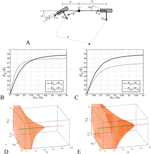
A stable domain of attraction, depending on tyre characteristics, was introduced in [Citation135]. The mechanical model of the vehicle is shown in Figure (A). The driver model delay was modelled with a first-order system. Five nonlinear ordinary differential equations represented the vehicle-and-driver motion. Both an understeering vehicle (tyre characteristic in Figure (B)) and an oversteering vehicle (tyre characteristic in Figure (C)) were considered. The two respective domains of attraction for the two vehicles are shown in Figure (D,E). The bell-like surfaces in Figure (D,E) define – roughly speaking – the stable domain of attraction, located inside the bell-like surface. Conversely, the unstable domain is located outside the bell-like surface. Notice that the two bell-like surfaces are bifurcation diagrams, defined by two main state variables, namely the lateral slips at the front and rear axle, respectively. By a linear transformation, the front and the rear axle slips can be substituted by the lateral speed at centre of gravity and the yaw rate, respectively. As the forward speed of the vehicle increases, the domain of attraction shrinks until a Hopf bifurcation is reached. By comparing Figure (D) with Figure (E), we immediately argue the influence of tyre characteristic on global stability. Actually, the shape of the bell-like surfaces cannot depend on factors other than tyre characteristics, being the mass properties of the vehicle and the driver the same in the two cases. No controls are active. The vehicle-and-driver system becomes unstable at a certain high speed, even if the vehicle is understeering [Citation135,Citation136].
Figure 6. (A) Mechanical vehicle model. (B) Front and rear tyre characteristics (nondimensional lateral forces as function of respective lateral slips) of an understeering vehicle (at low lateral slips). (C) same as B but for an oversteering vehicle. (D) Understeering vehicle. Stable domain of attraction (inside the bell-like surface), Hopf bifurcation occurs at a speed near to 50 m/s. (E) Oversteering vehicle. Stable domain of attraction (approximately inside the bell-like surface), Hopf bifurcation occurs at a speed near to 35 m/s.
The amplitude of the domain of attraction was studied in [Citation129] to compare different design solutions of controlled vehicle systems to enhance stability [Citation7]. In this case, the domain of attraction was given as a projection in the plane lateral velocity-yaw rate (Figure ).
Figure 7. Stable domain of attraction projected in the plane lateral velocity-yaw rate (adapted from [Citation129]).
![Figure 7. Stable domain of attraction projected in the plane lateral velocity-yaw rate (adapted from [Citation129]).](/cms/asset/fd4e0474-2bf7-4a28-971c-bc2a7f09a154/nvsd_a_2240447_f0007_ob.jpg)
In accordance to what was presented in [Citation129], in [Citation128,Citation137] the amplitude of the unstable limit cycle – after a subcritical Hopf bifurcation – was studied, due to control gains of tyre forces influencing yaw motion. The amplitude may vary up to 100% as function of control gains. In [Citation128], the effective axle characteristics (like in Figure (B)) were introduced and related to the stability domain.
A question arises now on the relationship between the amplitude of the stability domain and the force and moment measurement. Both the acceptable range on lateral force measurement and the uncertainty of the measurement system are to be estimated.
Acceptable range. The research on the amplitude of the stability domain is ongoing [Citation98,Citation102,Citation103,Citation126,Citation128,Citation134–137] and the respective values of forces at the boundary points have still to be understood and assessed. Nonetheless, tyre saturation seems to appear at some points at the stability domain border. This clue comes from an analysis performed in [Citation84], where, referring to the Milliken moment method [Citation138], Pacejka defines what happens at the tips of the so-called force–moment diagram (MMM diagram). The shape of such diagram resembles the stability boundary as introduced in [Citation129], additionally, in [Citation138], in Figure 8.11, a relationship between lateral force saturation and the force–moment diagram is given.
Since the amplitude of the stability domain seems somewhere related to lateral force saturation, the acceptable range of lateral force can be tentatively set equal to the one proposed in Section 3.1.
Uncertainty. Due to the above reasoning, the uncertainty can be tentatively set equal to the one proposed in Section 3.1.
Knowing in real time the domain of attraction, i.e. defining somehow the stability domain – as enabled by force and moment measurement – makes it possible to immediately forecast the evolution of the motion due to a disturbance. Collision warning and proper collision interventions can be designed and adopted. The impact on active safety is expected to be great, unfortunately, the real time estimation of the domain of attraction is still to be developed [Citation139].
3.4. Force and moment measurement for driver’s comfort, for driver model derivation and for active safety
The driver is subjected to a set of external forces that define the dynamic equilibrium of whole body [Citation140–142]. The interaction of the driver body with the vehicle occurs at the seat [Citation143–148], the safety belts [Citation149,Citation150], the steering wheel [Citation151–154] and the pedals [Citation155,Citation156].
Considerable interest is currently devoted not only to cognitive workload and related control of the steering wheel [Citation157], but also both to the neuro-muscular system, and to the dynamic posture of the driver as a multi-body system with flexible bodies [Citation142,Citation158–162].
Modelling the nonvoluntary steering actions due to an external excitation (e.g. a shock) may contribute to derive a robust vehicle-and-driver model for enhanced stability evaluation [Citation163]. This requires obviously force and moment measurement, particularly at the steering wheel. Referring to [Citation163], where an instrumented steering wheel is developed for measuring forces and moments at each hand, possible acceptable ranges on force and moment measurement are given, together with the related uncertainties of the measurement system.
Acceptable range. Full-scale values: Fx = Fy = Fz 750 N, Mx = My = Mz 75 Nm. Acceptable range: Fx = Fy = Fz 0.1 N, Mx = My = Mz 0.01 Nm.
Uncertainty. Fx = Fy = Fz 0.01 N, Mx = My = Mz 0.001 Nm.
3.5. Force and moment measurement for active safety of motorcycles
Two wheelers are inherently unstable vehicles as they are prone to capsize, wobble and weave. The driver stabilises, when possible, the vehicle-and-driver system [Citation1]. In [Citation164], a knowledge-based system of motorcycle safety was introduced and allowed to state that ‘automatic systems have the greatest potential to improve motorcycle safety’. Automatic systems based on force and moment measurement seem to be the most promising [Citation165], especially for hard braking and braking into a bend.
Measuring forces and moments may be particularly helpful to develop future safer two wheelers, referring both to active safety and structural safety (lightweight construction) [Citation166,Citation167].
Referring to [Citation168], where an instrumented motorcycle wheel is developed, possible acceptable ranges on force and moment measurement are given, together with the related uncertainties of the measurement system.
Acceptable range. Full-scale values: Fx = 5 kN, Fy = 2 kN, Fz 5 kN, Mx = 1 kNm My = 3 kNm, Mz = 1 Nm. Acceptable range: Fx = Fy = Fz 20 N, Mx = My = Mz 5 Nm.
Uncertainty. Fx = Fy = Fz 3 N, Mx = My = Mz 0.6 Nm.
3.6. Forces and moments data for lightweight construction improvement
Vehicle system dynamics is inherently related to load spectra that are used for vehicle lightweight design and structural safety issues [Citation1], Chapters 9–11.
Load spectra are used to refine the structural design for safety issues [Citation167,Citation170–172]. Road spectra depend on vehicle suspension settings [Citation173], vehicle mission (road irregular profile included) [Citation1,Citation174] and driver’s behaviour [Citation175]. Referring to current engineering practice, an accurate knowledge of load spectra pertaining to homogeneous fleets is crucial for designing lightweight, safe and noise-vibration-harshness efficient components [Citation176]. An accurate knowledge of load spectra for the single vehicle may solve safety problems related to misuse and litigations, involving a new focused life-cycle management of each vehicle [Citation177].
Measurement of force and moment on board of the vehicle allows not only to better refine lightweight construction and structural safety [Citation25,Citation178,Citation179] but also, eventually, to develop new and highly innovative solutions in the automotive sector. Actually, extreme lightweight might involve, in the future, design strategies similar to the ones typical of the aerospace sector. In [Citation180], in such a sector, the determination of costs and benefits from implementing a health management system is addressed. Continuous monitoring of the structural health of road vehicle components is beneficial. It allows the substitution of components as they reach their end-of-life. This might be cost effective as it occurs for aircrafts. The hypothesis that we address here is just an early reasoning that could become significant in the future.
Let us consider [Citation1, chpt.11] and [Citation181] where the energy demand to complete a driving cycle was discussed. Following such references and referring to WLTP driving cycle (Worldwide Harmonised Light Vehicles Procedure), the energy used to complete a cycle may be expressed as follows:
(5)
(5)
where EfES is the energy required to travel 240,000 km in 16 years [kWh]; A is the area of the cross-section of car body [m2]; cx is the drag coefficient [-]; ccx is the coefficient of driving cycle energy depending on aerodynamic forces [kJ/m2]; fr is the tyre rolling resistance coefficient [-]; cfr is the coefficient of driving cycle energy depending on rolling resistance [kJ/m2]; m is the vehicle curb mass and cfr is the coefficient of driving cycle energy depending on acceleration [kJ/m2].
Notice that, as outlined in [Citation1],
(6)
(6)
Referring to data presented in [Citation182], Figure (A) may be introduced for a common mid-size sedan. The lifecycle average energy demand is plotted as function of mileage. The energy is divided into two parts, Epmr refers to the energy used to produce, maintain and recycle the vehicle. The second part, EfES is the energy of the fuel (and of the energy supply) that is used to travel during the lifecycle of the vehicle. Such kind of a graph is used commonly to judge the sustainability of road vehicles [Citation183,Citation184].
In Figure (B), the lifecycle average energy demand is shown with a mass reduction of 30% with respect to Figure (A). Let us make the hypothesis that this mass reduction achievement could be obtained thanks to a continuous monitoring of the structural damage of a number of components by means of force and moment measurement.
Figure 8. (A) Life-cycle energy. Energy required to produce, maintain, use and recycle a sedan car (mass: 1415 kg, power/torque 110 kW/250 Nm, gasoline, declared fuel consumption 6.2 l/100 km). Epmr: energy demand to produce, maintain and recycle the car, EfES: energy demand to run the full milage and energy needed to supply the fuel (well to tank). (B) Comparison the life-cycle energies of three vehicles, namely, vehicle of (A), vehicle of (B) but 30% lighter, last vehicle in which 15% of the mass belongs to components that are substituted at midlife.
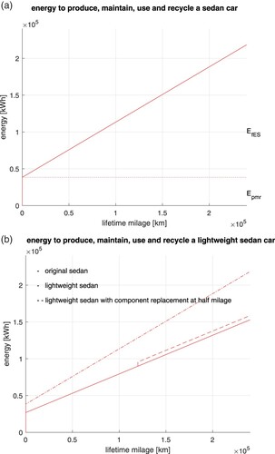
Epmr is proportional to m. Roughly speaking, EfES, expressed by Equation (5), is proportional to m, due to Equation (6). Reducing m implies reducing both Epmr and EfES, this is shown in Figure (B), where the energy to produce, maintain and recycle a conventional sedan car is compared with the corresponding energy of a 30% lighter sedan. A noticeable reduction of the lifecycle average energy demand can be obtained by lightweight construction.
In case the high mass reduction would require a component substitution at the midlife of the vehicle, a final positive result would be obtained as well, actually, by inspection of Figure (B), we see that, in case 15% of the mass of car components would be replaced, the lifecycle energy demand would be still lower than the one of the original car.
This simple example clarifies why the force and moment technology may be relevant for lightweight construction. Extreme lightweight construction may imply the replacement of components, with relevant benefits on greenhouse gas emissions, provided that structural safety is met [Citation25,Citation177–186].
According to [Citation1] Chapters 9 and 10, to [Citation167,Citation170] and Figure , the wheel force transducers on the marked provide already both the acceptable range on force measurement and the uncertainty of the measurement system. The data below refer to a mid-size car.
Acceptable range. Full-scale values: Fx = 10 kN, Fy = 10 kN, Fz 10 kN, Mx = 3 kNm My = 3 kNm, Mz = 2 kNm. Acceptable range: Fx = Fy = Fz 50 N, Mx = My = Mz 10 Nm.
Uncertainty. Fx = Fy = Fz 10 N, Mx = My = Mz 2 Nm.
Figure 9. (A) Force, longitudinal or lateral, as function of slip, longitudinal or lateral, respectively. On hard ground the most common curve force-slip has a maximum, not the same for gravel or melting ice or thick lubricant film. (B) SWIFT model as a representation of an actual tyre. Adapted from [Citation84]. (C,D) Stochastic nature of measured forces in longitudinal or lateral direction. Adapted from [Citation187].
![Figure 9. (A) Force, longitudinal or lateral, as function of slip, longitudinal or lateral, respectively. On hard ground the most common curve force-slip has a maximum, not the same for gravel or melting ice or thick lubricant film. (B) SWIFT model as a representation of an actual tyre. Adapted from [Citation84]. (C,D) Stochastic nature of measured forces in longitudinal or lateral direction. Adapted from [Citation187].](/cms/asset/b27668e6-303a-4abb-8aa2-a9165fe9c046/nvsd_a_2240447_f0009_oc.jpg)
4. How force and moment data can be used to improve active safety, stability enhancement systems and lightweight construction of road vehicles? What can be done with force and moment data?
Force and moment measurement technology may be used to enhance:
the active safety systems listed in Table , according to SAE J3063 [Citation6];
the automotive stability enhancement systems, listed in Table , according with SAE J2564 [Citation7], namely
ABS – Antilock Brake Systems
TCS – Traction Control Systems
ESC – Electronic Stability Control
to evaluate load spectra for structural safety and lightweight construction purposes, (Table ).
In the subsequent sub-sections, the rankings given in Tables will be clarified. Additionally, the research areas shown in Figure will be addressed. A special focus will be devoted to automotive stability enhancement systems as listed in Table [Citation7].
4.1. Safety envelope definition
Considering the car-following scenario within one lane, the safety envelope can be considered as the minimum following distance between two subsequent vehicles. Safety envelope is relevant for Automated Lane Keeping Systems (ALKS), proper of Level 3 (L3) automated vehicles. The size of the minimum following distance for L3 vehicles is defined by UNECE Regulation 157 [Citation30], as function of travelling speed. In the regulation, the friction at the tyre–ground is not used to size the minimum following distance, which is kept quite broad, in fact, it is set at 26.7 m, at the maximum attainable speed of 60 km/h. Referring to ACC and to L3 vehicles, in the literature, with exception of [Citation17], no comprehensive references have been found for the computation of the safety envelope – or minimum following distance – on the basis of friction potential evaluation. In [Citation17], authors claim that ‘The proposed friction estimation scheme enables the collision mitigation algorithm to adapt its critical distance (warning/braking distance) definitions with changing road surface conditions, resulting in improved performance (reduced impact speed)’.
By inspection of Figure (A), the minimum following distance can vary considerably if the respective decelerations of the two subsequent vehicles are different. The maximum available friction of each vehicle should be known in advance for setting correctly the minimum following distance as addressed in [Citation16] and in Section 3.2. Let us notice that the two friction potential coefficients for the two subsequent vehicles are in general different, due to the different tyres of the two vehicles. Additionally, friction may change along the road [Citation11].
A possible solution for distancing, still to be properly substantiated [Citation16], is as follows [Citation188]. The vehicle preceding the ego vehicle starts an emergency braking. Both vehicles are equipped with force and moment sensing, so the friction coefficient can be accurately and quickly measured by the two vehicles. The preceding vehicle may send data (by a V2 V system) on the current friction potential to the ego vehicle which gains an estimate of the friction it will experience as it goes on, following the preceding vehicle. So the ego vehicle may know in advance an estimate of the friction potential. In case of cut-in, the situation is more complex and will deserve in the future proper attention [Citation16].
Knowing the friction potential could decrease – or increase – considerably the minimum following distance, with respect to the values in Figure (A), with benefits for safety and traffic flow [Citation16].
On the basis of above considerations, one may argue how much safety envelope definition is relevant for entries 1.2, 2.1, 2.2, 3.1, 3.2, 3.3, 5.5 in Table .
4.2. Friction potential evaluation
In this section, we will deal with force and moment measurement technology for friction potential evaluation. We will compare such technology with
model -based friction potential estimation;
data -based friction potential estimation.
4.2.1. Friction potential evaluation through models of vehicles and/or tyres
The relevant questions are
conceptual definition of friction potential;
needed complexity for vehicle and/or tyre models;
accuracy of estimation;
time to evaluate the friction potential.
4.2.1.1. Conceptual definition of friction potential
In the literature, there are at least five state-of-the-art papers dealing with friction potential estimation or related topics [Citation13,Citation14,Citation76,Citation189,Citation190]. The inherent concept in all of such papers is that available friction (or adherence coefficient or friction potential) is a parameter (or set of parameters) pertaining to tyre and ground surface that exists (exist) and can be measured.
This assumption seems an abstraction since tyre characteristics – and maximum available friction – can be measured with reduced noise in laboratory condition only [Citation1,Citation85]. Typical force-slip characteristics at steady-state are shown in Figure (A). At relatively low speed, hysteresis occurs which requires more complex tyre models than the ones commonly used for steady state [Citation85].
When an actual wheel is interacting with irregular road and is subject to vibrations, the concept of friction potential can be defined by means of a stochastic process [Citation187,Citation191]. Let us consider Figure (B), where the SWIFT model is depicted. For such a complex case, the definition of the actual maximum horizontal force at the ground is inherently related to the state variables that describe the tyre structure as a flexible body. In this case, it is hard defining the maximum horizontal force as the product of friction potential by the vertical force. The common concept of friction potential pertains to a steady-state tyre model that is hardly working for limit adherence condition.
Experience shows that always the horizontal force (taken with some averaging metrics) saturates or drops [Citation84]. In this case, as shown in [Citation165] and in [Citation192], the ratio of measured horizontal force/measured vertical force, after a proper data processing, can be used for describing the complex phenomenon of tyre force saturation or drop.
Thus, a convenient way to define the friction potential may come from the actual measurement of vertical force and horizontal forces at the ground.
4.2.1.2. Needed complexity for vehicle and/or tyre models
Referring to vehicle models, the comprehensive state-of-the-art paper [Citation13] teaches how to estimate tyre forces in case they are not measured directly. The companion paper [Citation14] focuses on friction potential evaluation. The vehicle models that are proposed are relatively simple and hardly capture the phenomena occurring at limit conditions, where vibrations up to 100 Hz may be relevant [Citation1,Citation84]. In [Citation78], virtual sensors based on Kalman filtering are criticised for they are ‘overly simplistic’ models.
At high lateral acceleration levels on high grip surface, a very detailed vehicle model should be used to estimate all of the dynamic effects that may influence friction potential evaluation. This detailed vehicle model needs many hundreds of parameters to be reliable [Citation1,Citation83,Citation84,Citation119–124]. A SWIFT tyre model could be used [Citation84] to consider high-frequency transients.
Mass properties (mass, location of the centre of gravity, inertia tensor) should be known with high accuracy to provide a reliable digital twin of the actual vehicle. In [Citation193,Citation194], the acceptable uncertainties on mass properties data were given for reliable simulations. Such uncertainties were rather tight (few millimetres for the centre of gravity location, 3% for inertia moment values). Mass properties considerably vary due to the varying payload.
We can conclude that, at the limit conditions, a reliable vehicle model to be used to identify forces and moments needs so many parameter data that its usage is very unpractical. In case, parameter data could be available, the power needed to run a real time digital twin of the vehicle may be non negligible (0.5 kW or more), with questionable overall energy efficiency of the vehicle.
Referring to tyre models, following the early classification given by Hedrick et al. [Citation195], a distinction is made between caused-based and effect-based generalised force estimation. Caused-based estimation refers to analysing the status of the ground (wet, lubricated, with gravel) and estimating directly the friction potential. Effect-based estimation refers to analysing the kinematics of the vehicle and perform an identification of vehicle’s states variables, which are the input of a tyre model. In [Citation13,Citation14], different models can be used, namely Magic Formula, brush model, Dugoff/Fiala or others. Such models describe the behaviour of the wheel in a simplified way and thus limit the accuracy of friction potential evaluation.
The problem is to use a tyre model which is accurate enough [Citation84,Citation196–200] and reconstruct the whole combined characteristic (Fy, Fx, Mz) which depends, in the simplest case, on longitudinal slip sx, on lateral slip angle α, on camber angle γ, on vertical force Fz.
Temperature is an additional and necessary useful parameter for accurate tyre characteristic reconstruction [Citation196,Citation198]. The use of temperature information is crucial for accurate tyre characteristic reconstruction [Citation198]. The need to monitor temperature for accurate tyre characteristic estimation is not highlighted in a relevant manner in the main literature on force and moment estimation or friction potential estimation [Citation13,Citation14,Citation54,Citation199].
For decades [Citation195], estimating either the longitudinal slip sx or the lateral slip angle α requires an accurate estimation of the longitudinal speed, which is difficult if high longitudinal slips occur both at the front and at the rear axle. In [Citation195], a proper observer for estimating longitudinal speed is envisaged. Other papers dealing with such a problem are [Citation201,Citation202]. Estimation of vehicle speed is an issue for friction potential evaluation if forces are estimated (i.e. identified).
The lateral speed at the centre of gravity of the vehicle is hardly detected as well [Citation191,Citation203–205]. This is an additional problem for friction potential estimation in the lateral direction by means of a model-based approach.
Summarising, we have seen that estimating friction potential has been made resorting to tyre and vehicle models. A number of shortcomings exist, the most influential being: too simple tyre model, uncertain vehicle model.
Model-based friction potential evaluation necessarily involves force (and moment) measurement or estimation. Measuring directly forces and moments at the hubs solves the problem of estimating them by means of identification from mathematical models [Citation206,Citation207]. A general consensus appears in [Citation13,Citation14,Citation189,Citation190] on two facts, first, measuring forces and moments could be highly beneficial, second, force and moment measurement technology is too expensive or not yet ready for mass production.
We should remark here that friction potential evaluation may be investigated by other strategies other than force and moment measurement. Friction potential evaluation might be performed by studying low-frequency vibration of the wheel or high-frequency tyre noise as addressed briefly in [Citation14].
4.2.1.3. Accuracy of estimation
The accuracy on friction potential provided by measurement of forces and moments is in principle better than the one coming from force estimation [Citation208]. This occurrence is still not demonstrated conveniently. Actually, the accuracy obtained in [Citation209] with force and moment measurement is similar to the one obtained in [Citation208] with force estimation. This is due to the fact that measured forces are used to identify the parameters of a tyre model. Relatively accurate estimates of friction were given in [Citation75].
A common shortcoming, both for force measurement and for force estimation, is that, if a tyre model is employed, friction potential evaluation is to be performed at high slips, either longitudinal or lateral. This is to provide an accurate value of friction potential [Citation13,Citation14,Citation76,Citation190,Citation195,Citation206,Citation207,Citation210–215,Citation216,Citation217]. In the literature, levels of at least 70% of the maximum friction coefficient are recommended to estimate the friction potential with an accuracy better than 0.2 [Citation13,Citation14].
The so-called slip-slope effect, i.e. the influence on friction potential of the slope at the origin of the force-slip curve, is depicted in Figure . The slope of the force-slip curve depends on adherence at the ground [Citation1,Citation14,Citation195].
Referring to the uncertainty and the resolution of friction measurement, the reader may refer to Section 3.2 [Citation91–96].
In [Citation209], friction potential evaluation is obtained by force and moment measurement. The method is based on the Gough plot. Friction potential error is hardly lower than 0.1 either in longitudinal or lateral direction. This is due mainly to the effect of temperature, that on high-friction ground, heats quickly the tyre tread material [Citation198,Citation218].
For low-friction surfaces, the friction potential evaluation through force and moment sensing can be made in a simple way, taking inspiration from Svendenius [Citation214]. Forces and moments can be grouped and sorted within ‘data-bins’, as well, other data-bins can be used to sort the so-called input variables [Citation84], e.g. sx and α. The reported accuracy seems in line with the one from other papers [Citation93,Citation94].
In [Citation39], a convenient fusion of information is used for collision avoidance and ABS control. Environmental sensors, sensors measuring vehicle dynamics and experimental tyre sensors are used to estimate the friction potential. Less than 0.2 discrepancy between estimated and reference value of friction potential is achieved.
4.2.1.4. Time to evaluate the friction potential
The identification of the tyre parameters starting from forces and moments data (Fy, Fx, Mz) and from input variables (sx, α, γ, Fz) must be performed in milliseconds to be effectively used for sensing purposes. Actually, at high speed, e.g. 35 m/s, a 10 ms delay involves a travelled distance of 0.35 m. Such a distance seems too large if a sudden change of friction is to be detected.
Such a requested low-time interval is hardly found in the literature. Generally, if a relatively simple model for vehicle and tyre is used and a powerful hardware is employed, some tens milliseconds are needed by an EKF or UKF to converge. In case of friction coefficient transient, the convergence can take significantly more time. Such time data are often not properly addressed in the literature.
In [Citation209], with force measurement, some 100 ms are needed by the algorithm to converge to a stable value of the lateral friction potential. In [Citation200], with lateral force estimation, one second is needed. In [Citation96], the real time estimation of friction potential is performed mainly in the linear tyre characteristic range, the time needed seems still considerable. In [Citation17], a time of the order of one second seems needed to perform the evaluation of the friction potential. Authors claim that their own method could allow to reduce the impact speed of the ego vehicle against the preceding one.
In [Citation219], a new smart tyre is employed to predict road friction with encouraging results on real time evaluation. In [Citation220], the concept of real time seems still to be discussed in depth. In [Citation221], based on simulations, the delay to make the error between reference and estimated forces vanish seems needing few hundred milliseconds. In [Citation75], many graphs show that current friction at the tyres can be detected within tens of millisecond, approximately.
Force and moment measurement would need up to a couple of milliseconds to provide the data, generally, in the literature, such time data are not declared.
4.2.2. Friction potential evaluation through data collection
For the sake of space, only three contributions on the topic are dealt with. Other contributions may be found in [Citation13,Citation14,Citation78].
One of the more convincing papers on model-less friction estimation is [Citation210]. Two neural networks (NN) were used to estimate the road friction potential. The measured quantities were steering wheel angle, forces on the king pin, force on the steering link and suspension inclination angle. The second NN was aimed at estimating the wheel slips and friction potential.
One of the latest initiatives based on artificial intelligence is proposed in [Citation222], where a kind of a brief position paper can be found. Artificial intelligence is proposed because it
‘predicts road events far beyond the range of ADAS sensors reveals hidden roadway risks [on] rough wet or icy roads reveals hidden vehicle risks impending tire blowouts and more unlock innovative aftermarket services-better customer satisfaction-new data monetization models’
Cloud (or Big Data) to isolate vehicle-specific signal signatures is a promising technique yet to be thoroughly documented in the relevant literature.
A good contribution focusing on reliability of big data processing for active safety and stability enhancement is given in [Citation78].
One of the ongoing research directions is related to combination of model-based and data-driven approaches. As an example, an application on sideslip angle estimation is reported in [Citation223], similar studies are expected on road friction estimation.
On the basis of above considerations, one may argue how much friction potential measurement could be relevant for entries 1.2, 1.3, 2.1, 2.2, 2.4, 3.1, 3.2, 3.3, 5.2, 5.5 in Table .
4.3. ABS
In [Citation224], a book on active braking control deals with the basics of ABS systems. There are a number of papers in the literature dealing with how improving the ABS system by force and moment measurement [Citation33–37,Citation165,Citation191,Citation225]. The main advantage can be easily understood by considering the rotation equilibrium of the wheel.
where J is the moment of inertia of the wheel around its axis,
is the angular acceleration of the wheel, T is the torque applied by the brake, Fx is the tangential force and r is the instantaneous radius of the wheel. In the conventional ABS [Citation1,Citation2,Citation33,Citation224], both the speed of the vehicle and the angular acceleration of the wheel are used to apply the control logic of brake actuation [Citation1]. The angular acceleration of the wheel is proportional to the difference of two torques, namely T and Fxr. Notice that only one of them is related to adherence. By force and moment measuring technology both T and Fx r can be measured separately with direct info on adherence (Fx) and actuation effort (T).
Due to the complexity of the wheel (see e.g. the SWIFT model in Figure (B)), the forces at the ground have a complex frequency response, depending on tyre carcass vibration modes. Additionally, due to the road irregularity, Fx has a stochastic nature, as shown in Figure (C,D). Measuring Fx seems crucial for addressing all of these phenomena.
In [Citation33], a review is performed on eight different controls for ABS, namely Rule Based, Fuzzy Logic, Neural Networks, PID, LQR, Sliding Mode, Classical Robust Control and Model Predictive. Based on the gaps emerging from the analysis, a novel nonlinear model predictive control based on force sensing is proposed. Such a control ‘showed substantial reduction of the braking distance and better steerability’.
In [Citation34,Citation35], an instrumented low-cost smart wheel able to measure three forces and three moments was introduced. On μ-jump (i.e. on fast changing of tyre–ground friction), the ABS performance improvement with respect to a rule-based approach was obtained by adopting a sliding mode control. In [Citation31,Citation32], the ABS performance improvement has been confirmed by sensing forces by a smart tyre. In [Citation36], the force sensing was obtained by placing strain gauges at the bolts fixing the calliper to the strut. The strategy of instrumenting callipers was used in 1998 in [Citation226], this allowed to measure braking torque. In [Citation82], strain resistive elements on the brake calliper were employed and braking distance was apparently reduced. In [Citation17,Citation38], by exploiting an intelligent tyre, the limit friction coefficient was investigated for emergency braking purposes.
In [Citation165] and in [Citation37], authors propose a hybrid approach to let the longitudinal force be kept at the top of the tyre characteristic. The longitudinal force is measured. An improvement is found with respect to the base ABS control logic. A similar investigation, with corresponding results, is reported in [Citation81].
On the basis of above considerations, one may argue how much force and moment measurement has proved to be effective for ABS, as highlighted in Table .
4.4. Traction control systems (TCS) and electronic stability control (ESC)
According to [Citation14], the basic level of TCS, already estimates the road friction potential to adjust the thresholds during high dynamic excitation.
In [Citation40], a dual layer control for longitudinal forces is studied. The vehicle with force measurement shows more robust behaviour on slippery road with changing friction with respect to the vehicle with virtual force estimation. Basically, the same results are reported in [Citation34].
In [Citation41], a state-of-the-art review is proposed to tune torques for in-wheel motors but force and moment measurement is not cited. Additionally, in [Citation42,Citation43], the ESC and TCS are performed without force and moment measurement. On the contrary, in [Citation44], ESC is accomplished by measuring force by a sensorised bearing. ‘The ESC feed-forward control logic is designed through a vehicle frequency response analysis in order to obtain a faster active system activation. The tests demonstrate the opportunity of closing the control loop on a variable (i.e. the force) that can be directly measured’.
In [Citation45], force measurement with active front wheel steering is used to allocate the proper lateral forces that provide optimum lateral dynamic behaviour of a car.
In [Citation46], the cornering stiffness is estimated by means of a lateral force sensor based on a sensorised bearing. The slip-slope phenomenon is highlighted running on dry and wet ground.
In [Citation47], using the brush tyre model, the friction potential is evaluated at the left and right tyres respectively, by measuring with piezo-load cells the axial forces at the two connecting rods of a steering linkage system. The friction potential estimation requires the contact length information. In [Citation48], the ESC is proposed to be enhanced by measuring forces at the steering linkage, authors claim encouraging results. In [Citation227], tie-rods of the steering linkage are instrumented to derive the self-aligning torque, other relevant variables are estimated. The electronic power steering current is used to estimate the force applied at the steering rack. The friction of the steering linkage is somehow cancelled and considering the tyre self-aligning torque, the lateral grip margin is estimated. In [Citation53], steering torque provided by electric power steering is used to estimate the self-aligning torque and the friction potential. In [Citation54], a vehicle measurement system is used to derive tyre characteristics to be compared with indoor reference measurement. This vehicle instrumentation is only indirectly pertinent with the force and measurement technology dealt with in this paper.
In [Citation49], the results of the European project Friction are summarised.
The project demonstrated a near-continuous estimation of friction potential in changing road conditions, using sensor fusion and learning features. The project developed new sensing technology for classification of road conditions, especially for detecting ice, snow and water. The sensors included a polarisation camera system, new features for radar, features for laserscanner to detect weather, and improvements for Road Eye sensor.
In [Citation52], four electric motors in a car are used to apply opposite forces at the tyres in order to estimate cornering stiffness and tyre–road friction to enhance yaw dynamic behaviour.
In [Citation228], the falling of self-aligning torque with lateral slip is detected by the torque of the electric power steer motor. This enables the early detection of incoming understeer and improves the ESC with respect to current implementation.
Recently, controlling drifting manoeuvres has become a relevant topic [Citation55–58]. The exact estimation of the friction potential could provide a large improvement in the drift stabilisation capability of the vehicle when subjected to large slip angles. Relevant scientific contributions based on force and moment measurement technology seem still lacking on this topic.
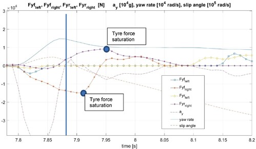
Finally, let us consider Figure , in which a complex model of a car (14 degrees of freedom) is virtually driven by a real human driver in the dynamic driving simulator of the Politecnico di Milano [Citation229]. The vehicle data in Appendix 3 refer to a slight oversteering car. An external disturbance acting for 100 ms applies both a lateral force at the vehicle centre of gravity and a yaw moment. After the disturbance has acted, both the front tyre and the rear left tyre saturate in a time interval of nearly 50 ms. At time 7.95s, the rear tyre lateral force reaches the peak value, but the sideslip angle is still limited, nearly 0.05 rad. At the same time, the yaw rate is dropping and the lateral acceleration is nearly 5 m/s2, a not too high value. Despite the fact that the kinematical variables’ values are not particularly worrying, force signals have reached critical values and may inform in advance that a spin is initiated, which the driver will not be able to counteract. The whole phenomenon lasts nearly 300 ms, no time for the driver to react. The data of forces are to be delivered quickly, within milliseconds to allow to plan and act [Citation10,Citation11]. In this case, force and moment technology might be very competitive with state estimation technology.
Figure 10. Response to a disturbance of a complex vehicle model, virtually driven by a real human in a dynamic driving simulator. Vehicle data in Appendix 3.
In [Citation230], an even higher delay (100 ms) was found between lateral force signal and yaw rate signal. The force signal represents the effect of a disturbance more quickly than the speed signal (this delay would be vanishing if the acceleration signal would be used).
On the basis of above considerations, force and moment measurement has proved to be very effective for TCS and ESC, as highlighted in Table .
4.5. Lightweight construction, structural safety and reliability
In [Citation231,Citation232], the methodology to measure forces acting at the wheels is presented, together with the steps to process data and derive load spectra. Measuring forces and moments at the wheels may greatly enhance vehicle health management. In [Citation177], a complete overview of such a topic is addressed which includes health monitoring and predictive maintenance. Not only the structural safety but the services involved in the process are important and can benefit from force and moment measurement technology. Vehicle misuse and related litigations may be dramatically decreased.
Referring to structural safety, in [Citation1], Chapter 9, the structural health of automotive components is dealt with. Referring to the possibility of having data on forces and moments, the following statement is reported.
The great advantage of measuring load data in comparison to local stresses and strains is that the former are independent of component geometry. By measuring load data, a system is described with which the results can be transferred to modified or similar systems. Thus, for the vehicle and machine manufacturing industries, load measurements form the basis of the continuous development of loading assumptions. This advantage can be used to increase the reliability of loading assumptions for designs, in particular the design of safety components. Moreover, by using long-term measuring concepts – the so-called ‘usage-monitoring’ – the changing usage-profiles and customer requirements can be initially determined or finally verified.
Recent contributions on load spectra measurement and evaluation are given in [Citation60,Citation62–65,Citation167,Citation170–176].
Referring to reliability, an overview is given in [Citation1], Chapter 10. In [Citation233], the concept of ‘wise sensorisation’ of vehicle components is introduced. The problem is how to decide whether or not a component is to be sensorised. The paradigm that appears is that, in general, sensors, being expensive, should always be used for multiple purposes. The sensorisation of components may be useful for
the digitalisation of the manufacturing process, with production cost savings;
improving active safety and the performance of stability enhancement systems;
the monitoring, during lifetime use, of structural health of components themselves;
degraded performance in case of a failure.
Premium production cars had more than 100 sensors in 2009 [Citation233,Citation234]. Nowadays, the number of sensors is roughly twice as much. This suggests that adding force and moment sensors for chassis control could be an affordable choice.
Referring to the reliability of active safety and stability enhancement systems, sensor data fusion [Citation233–238] can be used to solve the problem of minimising both the total probability of missed alarm UTOT(x) and the total probability of false alarm VTOT(x), where x, roughly speaking, is the number of sensors to be used, with a constraint on cost to be less than an affordable figure C(x)<C0.
where qU and qV are weights (qU + qV = 1); FIT is the number of failures in a time interval, 1 FIT corresponds to 1 failure in 109 h of working time of a single device [Citation239–241].
The final aim is to reach an ASIL D target [Citation239,Citation241,Citation243] which requires FIT < 10.
In this field, proper scientific contributions dealing with force and moment technology seem still missing.
4.6. Driver comfort and driver model derivation and monitoring
Driver is extremely sensitive to forces and moments exchanged at the steering wheel, especially during soft handling manoeuvers [Citation245,Citation246]. In the hard handling manoeuvres, the haptic feedback coming from the steering wheel is important too [Citation247]. A review is presented in [Citation244] referring to driver’s comfort performance requirement when interacting with ADAS. Unfortunately, the considerable number of papers listed in [Citation244] do not deal properly with force and moment measurement technology.
A research was performed in [Citation248] on forces and moment exchanged with the steering wheel by each hand. A test was performed at a driving simulator [Citation229]. While virtual driving along a motorway, a sudden dangerous event was created to stimulate driver’s reaction. The driver’s response to the stimulus was monitored by a heart rate variability band, by a skin resistance sensor, by a gaze acquisition camera, the signals were compared with the ones coming from a fully instrumented steering wheel [Citation163] (Figure ). The signal with the quickest response was the one pertaining to the grip force, followed by other force and moment signals. This shows the importance of measuring forces and moments at the steering wheel.
Figure 11. Driver in a dynamic driving simulator reacting to a stimulus occurring at time = 0s. The quickest biodynamic signal is the one of the grip force, measured by an instrumented steering wheel. Adapted from [Citation248].
![Figure 11. Driver in a dynamic driving simulator reacting to a stimulus occurring at time = 0s. The quickest biodynamic signal is the one of the grip force, measured by an instrumented steering wheel. Adapted from [Citation248].](/cms/asset/368479a1-f89d-44c9-94dd-31bcc965b59e/nvsd_a_2240447_f0011_oc.jpg)
Referring to driver model derivation, the neuro-muscular system activation can be studied effectively by measuring forces and moments at the steering wheel [Citation133,Citation162,Citation163,Citation249,Citation250,Citation251].
5. Force and moment sensor placement – how and where force and moment can be measured?
The force and moment measurement sensors for active safety, stability enhancement and structural health monitoring of road vehicles can be classified according with
position in the vehicle (wheel, steering wheel, etc., see Section 1, [Citation2]);
type of sensing structure (statically determined, non-statically determined);
sensing technology, i.e. transducer type (strain gauges, Hall effect, optical, etc.).
In the following sub-sections, the first classification will be adopted. Then the second classification will be introduced. The third classification will not be presented for the sake of space and because the topic is specific to experimental mechanics.
5.1. Classification of force and moment sensors as function of the position into the vehicle
5.1.1. Wheel force transducers (WFT) for cars or trucks and sensorised hubs
In [Citation252], a state-of-the-art paper reports many ways force and moment can be measured. Both statically determined structures and non-statically determined structures are presented. We will see below that both of the two structure types can be used for wheel force transducers, the first type being more promising. In [Citation253], a standard is reported to pursue force and moment measurement quality.
Non-statically determined structures are commonly employed for laboratory WFT. Such applications were presented in [Citation253,Citation255], where a first comparative evaluation of seven-wheel force transducers was presented. The three main technologies – still used when this paper is written – were compared, namely, strain gauged beam and spoke, individual load cells and mechanically separated load components. The accuracy as function of the rotation angle of the wheel was an issue. In [Citation255], a complete evaluation of the seven WFTs was performed and a synthesis is reported in Figure . In such a figure the main characteristics of a WFT are grouped. Notice that the uncertainty is few percent of full scale. Such a figure on uncertainty matches with the measurement uncertainty derived in Section 3.
Figure 12. Table of comparison of different wheel force transducers. Adapted from [Citation255].
![Figure 12. Table of comparison of different wheel force transducers. Adapted from [Citation255].](/cms/asset/73598b21-b90f-4866-9f6e-d4ba5bec278a/nvsd_a_2240447_f0012_ob.jpg)
Not only the accuracy of the WFT is important but also its stiffness, frequency response, mass and so on, as listed in Figure . In [Citation256], the resonance frequency of the wheel rim is taken into account to check the ability of current WFT to measure impact loads. The result is that the mass of the rim seems more important than rim stiffness.
In [Citation257,Citation258], devices are presented able to provide the three components of force and three components of moment acting at the wheel hub. They are widely used for research and development scopes [Citation259] since they can be adapted depending on the tyre size and on vehicle test stand. Several models are available, even for speed up to 350 km/h. Transducers can be divided into two main classes. Such sensors may have either strain gauge or piezo-load cells. Up to five 3-component load cells connected to the rim may be used in a non-statically determined structure. The signal is amplified, filtered and digitised. Temperatures up to 160°C may be reached. Sensors based on quartz (piezo) load cells replace the central part of the rim and can be mounted without any modification of the hub. Moreover, the adoption of quartz allows to sense dynamic loads up to very high frequency.
In [Citation260], a set of WFTs is presented, able to measure the three components of force and three components of moment applied to the hub. Strain gauges are used. Temperature variation is compensated. The structure of the sensors is not statically determined, with four spokes.
A six-axis wheel force sensor is shown in [Citation261]. It is to be mounted on the wheel hub for measuring in real time the three force and moment components acting at the hub. The non-statically determined sensing structure uses distributed force bridges for measurement and model-based decomposition. Compensation of thermal effects is claimed to be efficient.
In [Citation226], a lightweight six-axis WFT is shown, authors claim ‘It is the most accurate and best proven system on the market’, subsequent employment of the sensors could not be found in the literature.
In [Citation262], a WFT is shown which enables to measure the three force and three moment components separately. Again, a non-statically determined structure is used.
In [Citation263], a patent for wheel force dynamometer for measuring forces and moments acting on the tyre is presented. The loads acting on the tyre are transmitted to a rotor from the wheel rim. The rotor is hydrostatically mounted and axially fixed, while it can rotate along the circumferential direction. It transmits the loads to a housing, designed to be rigid in order to maximise the natural frequency of the dynamometer and, so, to reduce the measurement errors. The housing then transmits forces and moments to the force sensors (element (6) in Figure ). Measurement uncertainty is not reported.
Figure 13. Wheel force dynamometer. Adapted from [Citation263].
![Figure 13. Wheel force dynamometer. Adapted from [Citation263].](/cms/asset/8e0d9683-803a-42b0-8e97-a36dc96db0fe/nvsd_a_2240447_f0013_ob.jpg)
In 2003, a device was patented for detecting forces acting on the wheel [Citation264]. A detector is mounted in between the tyre and the hub holder. Again, the sensing structure is not statically determined. Accuracy is not reported. The device seems relatively simple and in principle could be tentatively used in big vehicle fleets (Figure ).
Figure 14. Detector for force acting on a tyre. Adapted from [Citation264].
![Figure 14. Detector for force acting on a tyre. Adapted from [Citation264].](/cms/asset/e4ec33c0-e53b-421c-800e-0616c8dba9cb/nvsd_a_2240447_f0014_ob.jpg)
In [Citation265,Citation266], two patents have been produced that were used to derive WFTs for cars or trucks [Citation267–270] (Figure ). Three components of force and three components of moments acting at the hub are measured. Contrary to previous designs, the sensing structure is statically determined (or semi-statically determined) which allows to keep parasitic stresses at a minimum level. Such a structure allows to cope with rim deformation and so a heavy stiff external ring is not needed, which allows a relatively lightweight construction. The declared measurement uncertainty is less than 1% in each of the channels. Temperature compensation is obtained by proper distribution of strain gauges.
Figure 15. (A) Wheel force transducer with three-spoke semi-statically determined sensing structure. Adapted from [Citation267,Citation268,Citation271]. (B) Calibration result.
![Figure 15. (A) Wheel force transducer with three-spoke semi-statically determined sensing structure. Adapted from [Citation267,Citation268,Citation271]. (B) Calibration result.](/cms/asset/e52ad85a-67ae-4adb-a4c6-4d88467520e8/nvsd_a_2240447_f0015_oc.jpg)
In [Citation272], a patent was filed referring to a low-cost WFT for light trucks, able to measure preferably the radial force. The rim is machined to obtain small slots for fitting small capacitors (Figure ). The accuracy is sufficient to assess the road damage effect by vertical force.
Figure 16. Wheel force transducer with the capacitor in a slot (indicated by arrow 4) to measure preferably the radial force. Adapted from [Citation272].
![Figure 16. Wheel force transducer with the capacitor in a slot (indicated by arrow 4) to measure preferably the radial force. Adapted from [Citation272].](/cms/asset/01d476dc-4205-4b63-8b13-ce78fd06b4c5/nvsd_a_2240447_f0016_ob.jpg)
Figure 17. Wheel end with load sensing capabilities. Adapted from [Citation273].
![Figure 17. Wheel end with load sensing capabilities. Adapted from [Citation273].](/cms/asset/ac8cffd1-71f8-4258-9636-05d49d5246ad/nvsd_a_2240447_f0017_ob.jpg)
5.1.2. Car suspension (hub carrier, upright, wheel carrier)
A wheel end featured by a sensing element for the real time estimation of forces was presented in [Citation273] (Figure ). The wheel end features a housing and a hub provided with a spindle that projects into the housing. The hub rotates with respect to the housing on an antifriction bearing located between the housing and the hub spindle. The housing features a tubular core that hosts the bearing and ring mounts. The rim is attached to the hub and rotates with respect to the housing. The housing is secured to a suspension upright by means of the ring mounts. The core deflects with respect to the ring mounts, due to forces and moments transferred through the bearing from the suspension upright to the tyre and vice-versa. The module of those forces and moments is reflected in signals derived from strain sensor modules (SM) attached to the webs of the housing. Also, this application seems structured to fit large vehicle fleets. Measurement uncertainty is not reported.
In [Citation274], a device involving a six-component load detection sensor embedded in the hub unit is presented. The cylindrical sensible element (highlighted with the number 111 in Figure ) is fixed in the space, being connected to a fitting part and connected to the hub by means of hub bearings. The sensible element is equipped with a bridge circuit including at least four strain gauges for each measured force or moment component, provided on the circumferential surface of the cylindrical part of the sensor. Measurement uncertainty and cross talk are not investigated in depth. It is a relatively simple device for big vehicle fleets.
Figure 18. Wheel forces detection device. Adapted from [Citation274].
![Figure 18. Wheel forces detection device. Adapted from [Citation274].](/cms/asset/8d6f9f67-034a-4e9b-ae57-1a61ef3b72f5/nvsd_a_2240447_f0018_ob.jpg)
Many patents related to sensorised bearings and suspension assemblies have been issued recently. A vast activity has been performed and an exhaustive report could not be delivered here.
In [Citation275], the deformation of the bearing outer-ring is used to detect forces and moments acting at the wheel hub (Figure ). Field tests were performed using an instrumented passenger car. Authors claim that the proposed approach is able to reconstruct both tilting and self-aligning moments as well as lateral and vertical wheel forces during various steering manoeuvres. In [Citation276], the sensorised bearing was applied to a wheel hub unit. The outer cylindrical surface of an outer ring of the wheel hub unit (bearing) has four circumferential flats equally spaced from each other. Each flat delimits a plane surface which extends axially over a pair of annular tracks for rolling bodies of the outer ring. Each flat carries integrally a sensor module including a pair of extensometers positioned parallel to each other and each at the position of a respective annular track. An electrical circuit picks up a signal from each sensor module and sends it to a data socket carried by the suspension upright or knuckle. Accuracy is not reported. The application is clearly devoted to the consumer market.
Figure 19. Sensorized wheel hub. Adapted from [Citation276].
![Figure 19. Sensorized wheel hub. Adapted from [Citation276].](/cms/asset/55b27476-80ed-470d-8097-b6b4966ca6c0/nvsd_a_2240447_f0019_ob.jpg)
In [Citation277], a dynamometric hub holder, instrumented by means of strain gauges properly located on the structure was developed (Figure ). The patent claims are very general. The sensing structure seems not statically determined.
Figure 20. Instrumented wheel carrier. Adapted from [Citation277].
![Figure 20. Instrumented wheel carrier. Adapted from [Citation277].](/cms/asset/354e917d-094e-48e3-a3ec-8c437ae0b744/nvsd_a_2240447_f0020_ob.jpg)
In [Citation278], a suspension hub carrier is presented with an integrated six-axis load cell [Citation80,Citation279]. The accuracy is high (1% FS). The stiffnesses in all of the directions of the hub carrier are similar to the ones of a reference hub carrier (Figure ).
Figure 21. Instrumented wheel carrier featuring a six-axis load cell [Citation278].
![Figure 21. Instrumented wheel carrier featuring a six-axis load cell [Citation278].](/cms/asset/86697e7e-2c84-4236-86b3-53f3cf6d3f4b/nvsd_a_2240447_f0021_oc.jpg)
5.1.3. Instrumented bearings
Instrumented bearings have several advantages with respect to other force and moment measuring technologies:
Easy signal collecting. The signals are gathered at the external non-rotating ring which solves the well-known problem of WFT that have to use a special device (e.g. slip ring) to cope with signals produced in a rotating element. Instead of a slip ring special device, a wireless transmission of signals can be used but this involves latency if a radio system is used (order of magnitude 10 ms). Cyber attacks are possible too. Gathering signals on a rotating element involves power to be delivered to the rotating element, which is not the case for a simple instrumented bearing.
Light construction. No additional heavy elements to unsprung masses are added as it occurs for WFT.
Reduced cost.
Different principles have been adopted to sense loads they are based on sensing:
deformations of rollers, of inner or outer ring;
displacements between different parts (e.g. outer ring and inner ring, or parts attached to them as flanges or abs thoothed ring).
One well-documented working principle is shown in Figure (C,D) [Citation85,Citation280]. The bending of the outer ring is sensed by strain gauges. The deformation depends on the position of the loading rolling element (either sphere or roller). The measurement accuracy depends on how accurately the deformation of the non-statically determined structure of the outer ring, plus connected structure (hub carrier) is modelled. A number of studies have been performed to increase the accuracy of such instrumented bearings. In [Citation280], a semi-analytical bearing model has been presented that addresses flexibility of the bearing outer race structure. This outperforms traditional rigid bearing models and seems enabling a promising way to compute deformations. In [Citation281], a cascade of state estimators, namely EKF and UKF, is successfully used to reduce the calibration effort of an instrumented bearing.
Figure 22. (A) Early attempt to measure forces by an instrumented bearing [Citation282]. (B) Positioning of capacitive sensors along the path surrounding the external ring. Adapted from [Citation283]. (C) General working principle of instrumented bearings. The strain gauge on the outer ring of the bearing senses when the roller or sphere is exactly on the sensor. Adapted from [Citation85]. (C) Radial ball bearing section view including relevant variables for (a) unloaded and (b) loaded conditions [Citation280].
![Figure 22. (A) Early attempt to measure forces by an instrumented bearing [Citation282]. (B) Positioning of capacitive sensors along the path surrounding the external ring. Adapted from [Citation283]. (C) General working principle of instrumented bearings. The strain gauge on the outer ring of the bearing senses when the roller or sphere is exactly on the sensor. Adapted from [Citation85]. (C) Radial ball bearing section view including relevant variables for (a) unloaded and (b) loaded conditions [Citation280].](/cms/asset/a75db92a-bcb9-4428-bc82-4c121feb80ae/nvsd_a_2240447_f0022_oc.jpg)
In [Citation284–286], standard strain gauges, semiconductor or piezoelectric strain gauges or fibre Bragg gratings are used to sense deformations to detect loads in components with bearings.
In [Citation287], a patent involving a device able to detect the load acting on a roller bearing is presented. The technology describes a load determining system including a sensorised rolling bearing mounted in a wheel hub unit. The system includes at least one magnetic sensor adopted to determine the loads acting on it based on the amplitude of the magnetic sensor output. Alternatively, the magnetic sensor can be substituted by a common deformation sensor. Furthermore, the system includes a signal processing unit configured to receive the magnetic sensor output.
In [Citation283], one or more capacitive sensors are used to compute the loads acting on the bearing, by measuring the deformation undergone by the outer ring (Figure ). The sensor measures the variation of capacitance producing an output voltage, depending linearly on the distance between the sensor and the outer ring. The output voltage is multiplied for a calibration constant, in order to compute the value of the applied load.
In [Citation288], a method for measuring the grip performance of a vehicle by interposing a carrier member in between an upright and an axle is described. A planetary bearing carrier is included in the load carrier member (Figure ).
Figure 23. System for measuring the grip performance of a vehicle. Adapted from [Citation288].
![Figure 23. System for measuring the grip performance of a vehicle. Adapted from [Citation288].](/cms/asset/cd3499f4-85b7-41d2-939f-8c118aed6ef9/nvsd_a_2240447_f0023_ob.jpg)
In [Citation289], a measuring ring is embedded in the wheel assembly of a farm tractor and positioned between the wheel bearing and the external housing. The idea on which this device is based is that a radial gap is presented between the measuring ring and the external housing. Adopting one or more displacement sensors, the variation of distance between the measuring ring and the housing is determined to compute the values of the forces acting on the wheel bearing (Figure ).
Figure 24. Load detection device for a wheel hub bearing. Adapted from [Citation289].
![Figure 24. Load detection device for a wheel hub bearing. Adapted from [Citation289].](/cms/asset/59ce8bb8-33e0-4f02-84e2-2e1575effe36/nvsd_a_2240447_f0024_ob.jpg)
In [Citation290], a configuration of load sensing bearing is presented. The patent in analysis, as shown in Figure , exploits an annular rib ring whose function is, in addition to constrain the rolling elements in between the internal ring and the external ring, to transfer the loads acting on the rolling elements to one or more sensors. The sensors can be deformation (involving the presence of strain gauges) or pressure sensors.
Figure 25. Load sensing bearing. The force on rollers is transferred outside the bearing. Adapted from [Citation290].
![Figure 25. Load sensing bearing. The force on rollers is transferred outside the bearing. Adapted from [Citation290].](/cms/asset/f9180f71-ad50-4eac-80fb-2e36aa751fc3/nvsd_a_2240447_f0025_ob.jpg)
In [Citation291], a method is described for which only the axial force acting on a wheel bearing can be estimated.
In [Citation292], a device is presented capable of estimating the braking force applied on a wheel by measuring the deformation acquired by the strain gauges positioned on its stationary part in connection with the brake calliper (Figure ).
Figure 26. Wheel bearing estimating the braking force. Adapted from [Citation292].
![Figure 26. Wheel bearing estimating the braking force. Adapted from [Citation292].](/cms/asset/7b7657ec-4e15-44b1-a35f-e1b695ce6d8c/nvsd_a_2240447_f0026_ob.jpg)
In [Citation293], a load-sensing antifriction bearing for a vehicle that senses wheel loads is presented. The load-sensing antifriction bearing supports a shaft connected to the wheel. The load-sensing antifriction bearing comprises an outer race having a flange, configured for attachment to the suspension upright. The bearing also comprises an inner race. Rolling elements are located in between the races. A sensor substrate attaches to the flange. Additionally, a sensor attaches to the sensor substrate wherein the sensor measures substrate strains, caused by radial expansions and contractions as the suspension upright experiences applied loads (Figure ). The non-statically determined structure has the common problems already mentioned describing sensorised bearings.
Figure 27. Load sensing wheel end. Adapted from [Citation293].
![Figure 27. Load sensing wheel end. Adapted from [Citation293].](/cms/asset/72e68a5b-268a-48c8-8a1a-157425f11440/nvsd_a_2240447_f0027_ob.jpg)
In [Citation46], the speed of rollers is somehow related to loads acting on the bearing.
5.1.4. Suspensions with instrumented arms for measuring forces and moments
Simple instrumentation of suspension arms may provide information on forces applied at the hubs. The practice is common in race cars [Citation294], as well as in laboratory [295]. Load cells or strain gauge sensors can be conveniently placed along arms in a five-link suspension [Citation2]. The configuration of the suspension is needed to compute the spatial resultant of forces, so at least one displacement sensor is needed. Elasto-kinematic effects are to be included for accurate measurement. In [Citation81,Citation296], the deformation of bushings at the joints between the suspension arms has been used to estimate the forces at the tyre–ground. The role of bushings has to be carefully taken into account [Citation296] because, as shown in [Citation295], the measurement accuracy depends on vibration frequency [Citation297].
A simple instrumentation of the suspension may be focused on steering rods [Citation47]. This does not allow to measure all of the force and moment components.
5.1.5. Motorcycle wheel
A dedicated technology has been developed for WFT of motorcycles [Citation271,Citation298,Citation299–306], actually, motorcycle wheels and tyres are structurally different from the ones of cars. In Figure , a WFT for motoGP or similar applications is shown [Citation168,Citation298,Citation307,Citation308], the structure is quasi-statically determined which allows a lightweight construction of the rim [Citation298]. Twelve strain gauges are applied at the three spokes. The signals are processed in the electronic card inside the wheel hub to provide three forces and three moments. Uncertainty on forces or moments is 1% FS, the complete measurement sheet is in [Citation298]. Such a wheel may be used for structural fatigue monitoring.
Figure 28. (A) WFT for MotoGP. Sensing structure based on quasi-statically determined structure [Citation271]. Adapted from [Citation309]. (B,C) Indoor tests up to 360 km/h. (D) Calibration of the wheel. Adapted from [Citation271].
![Figure 28. (A) WFT for MotoGP. Sensing structure based on quasi-statically determined structure [Citation271]. Adapted from [Citation309]. (B,C) Indoor tests up to 360 km/h. (D) Calibration of the wheel. Adapted from [Citation271].](/cms/asset/3a5362fe-b492-40e8-931b-8da1ef5f5bf0/nvsd_a_2240447_f0028_oc.jpg)
In [Citation309], a WFT for motorcycle is presented. ‘The wheel loads are detected by five strain gauge based 3-component measuring elements, which are arranged around the hub in circumferential direction’.
In [Citation310], another WFT for motorcycle is presented. The structure is non-statically determined. Three forces and three moments are measured.
5.1.6. Miscellaneous applications
The applications mentioned above refer mainly to car or truck or motorcycle applications, but in the literature, there are different papers and patented technologies referring to other application fields. Applications span from farm tractors to tracked vehicles [Citation267,Citation311–314].
In [Citation315], a measurement system of the three forces and three moments acting on the tyre is presented. The loads are identified by means of strain gauges mounted on two concentric circumferences of the rim for the considered wheel, measuring the radial deformation of the rim. The technology allows for the mounting of the two strain gauges series independently on the internal or the external side of the rim. For each circumference, four or more acquisition points are identified. A Wheatstone half-bridge or quarter-bridge configuration is adopted to generate deformation signals allowing the measurement of the loads in real time. Accuracy is not reported. With respect to the previous application, this one has the drawback that the signals are generated in a rotating member which creates data transmission problems.
In [Citation312], measuring hubs for fore and aft farm tractor axles were used to derive, maybe for the first time, the tyre characteristics during traction and braking on different surfaces, namely dry asphalt and loose terrain.
5.1.7. Steering wheel
In [Citation316–319], a number of commercial steering wheel torque systems are listed that are commonly used for research and development purposes. The accuracy is usually of the order of 0.01 Nm which is sufficient to detect small driver’s action.
Recently, attempts have been made to detect forces and moments and the grip force at each hand [Citation248,Citation318,Citation319]. The best hardware solution is able to measure forces of 0.1 N while resisting shock forces of 750 N. In Figure , a steering wheel able to measure the forces and three moments at each hand plus grip force at each hand is shown.
Figure 29. (A) Steering wheel able to measure the forces and three moments at each hand plus grip force at each hand. (B) Measurement uncertainty. Adapted from [Citation163].
![Figure 29. (A) Steering wheel able to measure the forces and three moments at each hand plus grip force at each hand. (B) Measurement uncertainty. Adapted from [Citation163].](/cms/asset/fa8765e1-ddf5-4f2c-ae09-5ea5317b23a3/nvsd_a_2240447_f0029_oc.jpg)
5.2. Classification of force and moment sensors as function of the type of sensing structure
In Table , the following types of sensing structures are compared:
statically (or quasi-statically) determined;
non-statically determined.
Table 4. Comparison of statically determined structure and non-statically determined structures for force and moment measurement technology.
The non-statically determined structures are divided into four or more spoke structures, instrumented bearings and instrumented suspensions.
Pros and cons of the different solutions are highlighted in Table .
5.3. Comparison of chassis technologies for force and moment measurement
In Table , a summary is reported on the addressed technologies for measurement forces and moments at the chassis.
Table 5. Chassis technologies for force and moment measurement.
6. When did force and moment measurement start being used to enhance active safety and structural safety of road vehicles? A historical perspective on past activities
It seems that the first force and moment measurement of tyre forces have been made in Germany and in the United States in the early thirties of the last century [Citation325,Citation326]. In [Citation326], the self-aligning torque was measured by reading the pressure in a reacting piston chamber connected to the steering rod (Figure (A)). In 1954, a plank with a force sensor was used by Gough to measure tyre lateral forces (Figure (B)) [Citation327].
Figure 30. Early tyre force measurement systems. (A) Test rig employed by Bull (1939). (B) Test rig employed by Gough (1954). Adapted from [Citation327].
![Figure 30. Early tyre force measurement systems. (A) Test rig employed by Bull (1939). (B) Test rig employed by Gough (1954). Adapted from [Citation327].](/cms/asset/d48d1990-90d0-4e1e-b6c2-9031525b918d/nvsd_a_2240447_f0030_oc.jpg)
It seems that the first WFT was presented in 1974 [Citation325]. Figure shows the sensing structure, a non-statically determined structure, which is not much dissimilar from the ones used today (see Section 5.1). Strain gauges were employed.
Figure 31. Early wheel force transducer. Non-statically determined structure. Adapted from [Citation325].
![Figure 31. Early wheel force transducer. Non-statically determined structure. Adapted from [Citation325].](/cms/asset/6abeb588-92ae-46bc-8481-c315db837f4e/nvsd_a_2240447_f0031_ob.jpg)
In [328], a critical review (up to 1977) of tyre force and moment measurement was given. The technology is not very far from the one used today, except from advanced sensing structures (see Section 5) and digital acquisition systems.
With the tyre data, one of the first more comprehensive and rigorous contributions on modelling of the dynamic behaviour of a vehicle was given in [Citation326]. Since then, the history of vehicle system dynamics and related force and moment measurement grew at the level addressed in this paper.
7. Discussion
Despite the large number of references cited in the paper, the authors would like to point out that important contributions may have been missed. Actually, the virtual sensing of forces and moments, that has been compared with the actual measurement of forces and moments, is a huge field of research, taking a substantial portion of Vehicle System Dynamics.
It is not the aim of the paper defining the economic convenience for car manufacturers to adopt the force and moment measurement technology. The main pros and cons of the technology from the scientific/technical point of view have been highlighted.
In a long-term perspective, the virtual force sensing based on state estimation is not competing with the force and moment measurement technology.
Actually, for safety reasons, especially in a degraded situation due to a fault, a redundant set of information is needed. Both virtual estimation and actual measurement of forces and moments could be useful.
Additionally, all of the problems relating to high-frequency vibration, e.g. noise vibration-harshness at the tyre-suspension level, will need further scientific contributions based on typical sw techniques (more than hw techniques).
8. Conclusion
The aim of the paper was to clarify why, what and where force and moment could be measured in a road vehicle to improve:
ctive safety systems;
stability enhancement systems;
lightweight construction.
Concerning why force and moment measurement technology could be introduced in modern vehicles, the key results are as follows:
The accuracy of force and moment measurement that is needed for effectively describing the longitudinal motion and/or the lateral motion of vehicles seems quite high, some examples have been produced. Currently, force and moment sensors seem providing the needed uncertainty. We must point out that, at the moment, there is an almost complete lack of generally accepted information on which is the needed uncertainty for force and moment measurement in relevant driving scenarios or manoeuvres.
For sensing purposes, force and moment data should be available as soon as possible (very few milliseconds at maximum) to plan and act for a proper control. In the literature, the delay for force and moment estimation by means of model state estimation is sometimes not properly addressed. Such a delay seems spanning from tens to hundreds of milliseconds or, sometimes, much more. Currently, force and moment sensors can provide data very quickly (usually, less than few milliseconds).
Force and moment data might be used to enable advanced lightweight construction and vehicle health management, this allows a synergistic action with active safety and stability enhancement.
Concerning what can be done with force and moment data, particular attention has been devoted to the following relevant topics.
Referring to safety envelope definition, force and moment measurement technology is expected to provide the most accurate friction data to define the highest possible deceleration. The key problem for distancing is to know in advance the friction potential. This problem of in-advance knowledge could be effectively implemented in the future by considering data exchange among vehicles equipped with force and moment sensors (CCAM, cooperative, connected and automated mobility).
Referring to friction potential evaluation, model-based evaluation has been performed in the literature with reference to very simple models, generally not considering either the transient behaviour or the stochastic nature of vertical force excitation.
Model-based friction potential evaluation seems still to be investigated by means of complex tyre models, in this case, force and moment measuring technology could be extremely helpful.
Data-based friction potential evaluation could be performed effectively with force and moment measuring technology.
Referring to ABS, force and moment measuring technology has proved to provide better deceleration than the one deriving from the currently known control logic. An effective approach is the so-called hybrid one, in which the maximum force is approximated, allowing very small oscillation of the force in the neighbourhood of the peak (in case the peak exists).
Referring to TCS and ESC, as for ABS, a number of papers in the literature have already highlighted the benefits coming from the exploitation of force and moment measurement technology. A relevant question is whether signals from forces are anticipating the signals pertaining to kinematics variables of the vehicle body. Generalised resultant forces and related accelerations are synchronous, as expected from the dynamic equilibrium of bodies with invariant mass. The generalised speeds are often delayed with respect to force signals, as it is expected from a harmonic analysis. Single forces (not force resultants) could provide additional information for instability mitigation.
Referring to lightweight construction and structural safety, force and moment measurement technology may allow:
vehicle health management, in particular: monitoring of vehicle misuse and related litigations, increase the reliability of loading assumptions for design of safety components;
enable advanced concepts of lightweight construction thus reducing greenhouse gas emissions;
enable the digitalisation of both components and their production process.
Referring to driver comfort and driver model derivation and monitoring, instrumented steering wheels, able to measure forces and moments, seem able to detect quickly driver’s psychological status.
Concerning how and where force and moment data can be collected, the main technologies that have been addressed are:
wheel force transducers, in particular economic wheel force transducers, either for cars, trucks, farm tractors or motorcycles;
instrumented bearings;
instrumented suspension systems;
instrumented steering wheels for driver modelling or monitoring.
All such technologies have pros and cons. The most promising technologies are the ones that
do not need wireless data transfer nor energy supply on rotating wheels, provide low latency for data transfer and are resilient against cyber attacks
Instrumented (or sensorised or load sensing) bearings have a huge development potential. It seems that they should the fitted into the hub carrier with a proper design solution to overcome the known problems typical of non-statically determined structures (causing cross talk among different channels).
Instrumented suspensions have a great potential as they could provide a good compromise between accuracy (good) and cost (low).
Instrumented steering wheels able to measure forces and moments at each hand are expected to allow both accurate driver model development and driver monitoring in the future.
Many of the addressed technologies for force and moment measurement possess a high Technology Readiness Level (TRL 6 up to TRL 9) which allows them to be fully considered for final investments aimed at mass production implementation.
Acknowledgements
Dr B. Shyrokau is acknowledged for having shared with the authors the material of his class delivered at the Delft University of Technology, concerning Wheel Load Reconstruction. Additionally, the discussion with him was very fruitful to strengthen some of the ideas produced in the paper. Dr Eric Tseng, formerly senior technical leader at Ford Motor Company, is acknowledged for a stimulating discussion. Ing. F. Ghirardi, head of vehicle design team at Ferrari is acknowledged for having reviewed the manuscript. Ing. M. Barani and Ing A. De Marco are acknowledged for having analysed some of the papers cited in the literature. Prof. S. Manzoni of Politecnico di Milano has provided considerable help concerning the metrological concepts.
Disclosure statement
Some of the devices presented in paper are produced by a spin-off of the Politecnico di Milano.
Correction Statement
This article has been corrected with minor changes. These changes do not impact the academic content of the article.
Additional information
Funding
References
- Mastinu G, Ploechl M. Road and off-road vehicle systems dynamics. Boca Raton: CRC Press; 2014.
- Bosch. Automotive handbook. Warrendale: SAE; 2018.
- Peng H, Chen X. Active safety control of X-by-wire electric vehicles: a survey. SAE Int J Veh Dyn Stab NVH. 2022;6(2):115–133. DOI:10.4271/10-06-02-0008
- ccam.eu. [cited 2023 Jan].
- SAE J3088 Active Safety System Sensors; 2017.
- SAE J3063 Active Safety Systems Terms and Definitions; 2021.
- SAE J2564 Automotive Stability Enhancement Systems; 2017.
- Ballo F, Gobbi M, Mastinu G, et al. Optimal lightweight construction principles. Berlin: Springer; 2020.
- United Nation Office for Disaster Risk Reduction. https://www.undrr.org/theme/structural-safety [cited 2023 June].
- ISO 21448. 2022 Road vehicles — Safety of the intended functionality.
- ACEA. Safety first for automated driving, 2019. [cited 2023 Jan]. https://group.mercedes-benz.com/documents/innovation/other/safety-first-for-automated-driving.pdf.
- SAE J3016 Recommended Practice. Taxonomy and definitions for terms related to driving automation systems for on-road motor vehicles; 2021.
- Acosta M, Kanarachos S, Blundell M. Virtual tyre force sensors: an overview of tyre model-based and tyre modelless state estimation techniques. Proc Inst Mech Eng Part D J Automob Eng. 2018;232(14):1883–1930. doi:10.1177/0954407017728198
- Acosta M, Kanarachos S, Blundell M. Road friction virtual sensing: a review of estimation techniques with emphasis on low excitation approaches. Appl Sci. 2017;7(12):1230.
- Schuster R, Weic“sler P. Der Kraftschluss Zwischen Rad und Fahbahn. ATZ; 1935, p. 499–504.
- Matin A, Dia H. Impacts of connected and automated vehicles on road safety and efficiency: a systematic literature review. IEEE Trans Intell Transp Syst. 2023;24(3):2705–2736. DOI:10.1109/TITS.2022.3227176
- Singh K, Arat M, Taheri S. Enhancement of collision mitigation braking system performance through real-time estimation of tire-road friction coefficient by means of smart tires. SAE Int J Passeng Cars Electron Electr Syst. 2012;5:607–624. DOI:10.4271/2012-01-2014
- ISO 21717. 2018 Intelligent Transport Systems – Partially Automated In-Lane Driving Systems (PADS) – Performance Requirements and Test Procedures.
- ISO 22839. 2013 Intelligent transport systems – forward vehicle collision mitigation systems – operation, performance, and verification requirements.
- ISO 17361. 2017 Intelligent transport systems – lane departure warning systems – performance requirements and test procedures.
- ISO 16787. 2017 Intelligent transport systems – assisted parking system (APS) – performance requirements and test procedures.
- ISO 22840. 2010 Intelligent transport systems – devices to aid reverse manoeuvres – extended-range backing Aid systems (ERBA).
- ISO 2416 Passenger cars. Mass distribution.
- UNECE Regulation 13. Braking.
- Kadakuntla S, Mohapatra DP, Kangde S. Spot weld fatigue correlation improvement in automotive structures using stress based approach with contact modelling. SAE Technical Papers, 2020-April; 2020.
- ISO 11067. 2015 Intelligent transport systems – curve speed warning systems (CSWS) – performance requirements and test procedures.
- ISO 15622. 2018 Intelligent transport systems – adaptive cruise control systems – performance requirements and test procedures.
- ISO 11270. 2014 Intelligent transport systems – lane keeping assistance systems (LKAS) – performance requirements and test procedures.
- ISO 17387. 2008 Intelligent transport systems – lane change decision aid systems (LCDAS) – performance requirements and test procedures.
- UNECE Regulation 157. Uniform provisions concerning the approval of vehicles with regard to automated lane keeping systems.
- Cheli F, Sabbioni E, Sbrosi M, et al. Enhancement of ABS performance through on-board estimation of the tires’ response by means of smart tires. SAE papers 2011-01–0991; 2011.
- Cheli F, Leo E, Melzi S, et al. On the impact of smart tyres on existing ABS/EBD control systems. Veh Syst Dyn. 2010;48:255–270. DOI:10.1080/00423111003706755
- Pretagostini F, Ferranti L, Berardo G, et al. Survey on wheel slip control design strategies, evaluation and application to antilock braking systems. IEEE Access. 2020;8:10951–10970. DOI:10.1109/ACCESS.2020.2965644
- Gobbi M, Botero JC, Mastinu G. Improving the active safety of road vehicles by sensing forces and moments at the wheels. Veh Syst Dyn. 2008;46(Suppl.1):957–968. DOI:10.1080/00423110802037198
- Botero JC, Gobbi M, Di Piazza N, et al. On the reformulation of the ABS logic by sensing forces and moments at the wheels. IFAC Proc Vol. 2007;40(10):265–272.
- de Carvalho Pinheiro H, Sisca L, Carello M, et al. Methodology and application on load monitoring using strain-gauged bolts in brake calipers. SAE Technical Paper 2022-01-0922; 2022. DOI:10.4271/2022-01-0922.
- Kerst S, Shyrokau B, Holweg E. Anti-lock braking control based on bearing load sensing). Proceedings of eurobrake; Dresden, Germany; May 2015, p. 4–6.
- Singh K, Taheri S. Estimation of tire-road friction coefficient and its application in chassis control systems. Syst Sci Control Eng. 2004;3(1):39–61.
- Koskinen S, Sensor data fusion based estimation of tyre-road friction to enhance collision avoidance. PhD thesis, Tampere University of Technology, Tampere, Finland; 2010.
- Riva G, Mozzarelli L, Corno M, et al. Direct longitudinal force feedback for high-performance vehicle dynamics control systems; 2021.
- Kanchwala H, Rodriguez P, Mantaras D, et al. Obtaining desired vehicle dynamics characteristics with independently controlled in-wheel motors: state of art review. SAE Int J Passeng Cars Mech Syst. 2017;10(2):413–425. DOI:10.4271/2017-01-9680
- Thang Truong DV, Meywerk M, Tomaske W. Torque vectoring for rear axle using adaptive sliding mode control. In 2013 International Conference on Control, Automation and Information Sciences, ICCAIS; 2013, p. 328–333.
- Velazquez Alcantar J, Assadian F, Kuang M. Optimal tire force control & allocation for longitudinal and yaw moment control of HEV with eAWD capabilities. SAE Int J Veh Dyn Stab NVH. 2017;1(2):220–233. DOI:10.4271/2017-01-1558
- Morgando A, Velardocchia M, Vigliani A, et al. An alternative approach to automotive ESC based on measured wheel forces. Veh Syst Dyn. 2011;49(12):1855–1871. DOI:10.1080/00423114.2010.548526
- Kunnappillil Madhusudhanan A, Corno M, Holweg E. Sliding mode-based lateral vehicle dynamics control using tyre force measurements. Veh Syst Dyn. 2015;53:1599–1619. DOI:10.1080/00423114.2015.1066018
- Kanghyun N. Application of novel lateral tire force sensors to vehicle parameter estimation of electric vehicles. Sensors. 2015;15:28385–28401. DOI:10.3390/s151128385
- Matilainen M, Tuononen A. Tire friction potential estimation from measured tie rod forces. IEEE Intelligent Vehicles Symposium (IV), Baden-Baden, Germany; 2011, p. 320–325. DOI:10.1109/IVS.2011.5940528
- Andersson M, Bruzelius F, Casselgren J, et al. Road friction estimation Part II. Sweden: Intelligent Vehicle Safety Systems (IVSS) Project Report; 2010.
- Koskinen S, Peussa P, Varpula T, et al. Friction, European Project, Deliverable 13 Final Report. Espoo: Technical Research Centre of Finland; 2004.
- Luque P, Mantaras D, Fidalgo E, et al. Tyre-road grip coefficient assessment–part II: online estimation using instrumented vehicle, extended Kalman filter, and neural network. Veh Syst Dyn. 2013;51:1872–1893. DOI:10.1080/00423114.2013.841963
- Yasui Y, Tanaka W, Muragishi Y, et al. Estimation of lateral grip margin based on self-aligning torque for vehicle dynamics enhancement. SAE Technical Paper 2004-01-1070; 2004.
- Wang R, Wang J. Tire-road friction coefficient and tire cornering stiffness estimation based on longitudinal tire force difference generation. Control Eng Pract. 2013;21:65–75. DOI:10.1016/j.conengprac.2012.09.009
- Hsu Y, Laws SM, Gerdes GJC. Estimation of tire slip angle and friction limits using steering torque. IEEE Trans Control Syst Technol. 2010;18(4):896–907, 5286226.
- Van Gennip MD, McPhee J. Parameter identification for combined slip tire models using vehicle measurement system. SAE Int J Veh Dyn Stab NVH. 2018;2(4). DOI:10.4271/2018-01-1339
- Acosta M. Research on multi-actuated agile electric vehicles: a drift-based approach to last-moment accident avoidance manoeuvres on loose surfaces. PhD thesis, Coventry University, Coventry, UK; 2017.
- Velenis E, Katzourakis D, Frazzoli E, et al. Steady-state drifting stabilization of RWD vehicles. Control Eng Pract. 2011;19(11):1363–1376.
- Goh JY, Goel T, Christian Gerdes J. Toward automated vehicle control beyond the stability limits: drifting along a general path. ASME J Dyn Sys Meas Control. 2019;142(2):021004. DOI:10.1115/1.4045320
- Edelmann J, Plöchl M. Controllability of the powerslide motion of vehicles with different drive concepts. Procedia Eng. 2017;199:3266–3271. DOI:10.1016/j.proeng.2017.09.357
- Shibahata Y, et al. Improving of vehicle maneuverability by direct yaw moment control. Veh Syst Dyn. 1993;22:465–481. DOI:10.1080/00423119308969044
- Baskin D, Reed D, Seel T, et al. A case study in structural optimization of an automotive body-in-white design. SAE Technical Paper 2008-01-0880; 2008. DOI:10.4271/2008-01-0880
- Crolla D. Encyclopedia of automotive engineering. Wiley (NJ): pn; 2014.
- Malen D. Fundamentals of automobile body structure design. Warrendale: SAE; 2011.
- Pang Y, Prokop G. Indoor measurements of tire and road data – applications to structural safety loads prediction (2021). SAE Int J Veh Dyn Stab NVH; 5 (3):369–378.
- Barbash K, Mars W. Critical plane analysis of rubber bushing structural safety under road loads, SAE Technical Paper 2016-01-0393; 2016. DOI:10.4271/2016-01-0393
- SAE Surface Vehicle Standard. Wheels – passenger car and truck performance requirements and test procedures. SAE Standard J328, Rev.; Feb 2005.
- Pfeffer P, Harrer M. Steering handbook. Berlin: Springer; 2017.
- JCGM100:2008. Evaluation of measurement data — guide to the expression of uncertainty in measurement (GUM) (see clause 2).
- JCGM 101:2008. Evaluation of measurement data– Supplement 1 to the “Guide to the expression of uncertainty in measurement”– Propagation of distributions using a Monte Carlo method (see clause 2).
- JCGM102. Evaluation of measurement data– Supplement 2 to the “Guide to the expression of uncertainty in measurement”– Models with any number of output quantities.
- JCGM103. Evaluation of measurement data – Supplement 3 to the “Guide to the expression of uncertainty in measurement”– Modelling.
- JCGM104. Evaluation of measurement data – An introduction to the “Guide to the expression of uncertainty in measurement” and related documents [this document].
- JCGM105. Evaluation of measurement data – Concepts and basic principles.
- JCGM106. Evaluation of measurement data – The role of measurement uncertainty in conformity assessment.
- JCGM107. Evaluation of measurement data – Applications of the least-squares method.
- Ray R. Nonlinear tire force estimation and road friction identification: simulation and experiments. Automatica. 1997;33:1819–1833. DOI:10.1016/S0005-1098(97)00093-9
- Khaleghian S, Emami A, Taheri S. A technical survey on tire-road friction estimation (Open Access). Friction. 2017;5(2):123–146. http://www.springer.com/engineering/mechanical+engineering/journal/40544.
- Ferrero A, Ferrero R, Jiang W, et al. The Kalman filter uncertainty concept in the possibility domain. IEEE Trans Instrum Meas. 2019;68(11):4335–4347. DOI:10.1109/TIM.2018.2890317
- Ayyad A, Prohm C, Gräber T, et al. Uncertainty estimation for neural time series with an application to sideslip angle estimation. SAE Int J CAV. 2021;4(3):247–259. DOI:10.4271/12-04-03-0020
- Tuononen A. Vehicle lateral state estimation based on measured tyre forces. Sensors. 2009;9(11):8761–8775. DOI:10.3390/s91108761
- Gobbi M, Previati G, Guarneri P, et al. A new six-axis load cell. Part II: error analysis, construction and experimental assessment of performances. Exp Mech. 2011;51(3):389–399. DOI:10.1007/s11340-010-9350-6
- Chae C-K, Bae B-K, Kim K-J, et al. A feasibility study on indirect identification of transmission forces through rubber bushing in vehicle suspension system by using vibration signals measured on links. Veh Syst Dyn. 2000;33:327–349. DOI:10.1076/0042-3114(200005)33:5;1-Q;FT327
- Ohkubo N, Horiuchi T, Yamamoto O, et al. Brake Torque sensing for enhancement of vehicle dynamics control systems. SAE Technical Paper 2007-01-0867; 2007. DOI:10.4271/2007-01-0867
- Mitschke M, Wallentowitz H. Dyanmik der Kraftfahrzeuge. Berlin: Springer; 2015.
- Pacejka HB. Tyre and vehicle dynamics. 2nd ed. Oxford: Butterworth and Heinemann (also SAE); 2002 [2006; 3rd ed., 2013].
- Nishikawa K. Hub bearing with integrated multi-axis load sensor. NTN Technical Review No.79; 2011.
- ISO 19364:2016 Passenger cars. Vehicle dynamic simulation and validation — steady-state circular driving behaviour.
- Shalev-Shwartz S, Shammah S, Shashua A. On a formal model of safe and scalable self-driving cars. arXiv:1708.06374 [cs, stat]; 2017.
- Flores C, Spring J, Nelson D, et al. Enabling cooperative adaptive cruise control on strings of vehicles with heterogeneous dynamics and powertrains. Veh Syst Dyn. 2023;61 (1):128–149. DOI:10.1080/00423114.2022.204256
- Doeblin E. Measurement systems, application and design. New York: McGraw-Hill; 2004.
- O’Neill A, Prins J, Watts JF, et al. Enhancing brush tyre model accuracy through friction measurements. Veh Syst Dyn. 2022;60(6):2075–2097. DOI:10.1080/00423114.2021.1893766
- Alhasan A, Smadi O, Bou-Saab G, et al. Pavement friction modeling using texture measurements and pendulum skid tester. Transp Res Rec. 2018;2672(40):440–451. DOI:10.1177/0361198118774165
- Carmon N, Ben-Dor E. Mapping asphaltic roads’ skid resistance using imaging spectroscopy. Remote Sens. 2018;10(3):430. DOI:10.3390/rs10030430
- Erdogan G, Alexander L, Rajamani R. Closed-loop snowplow applicator control using road condition measurements. Veh Syst Dyn. 2011;49(4):625–638. DOI:10.1080/00423111003653551
- Erdogan G, Alexander L, Rajamani R. Friction coefficient measurement system for winter maintenance vehicles. Proceedings of the American Control Conference, Art. No. 4587218; 2008, p. 4585–4590.
- Choubane B, Holzschuher CR, Gokhale S. Precision of locked-wheel testers for measurement of roadway surface friction characteristics. Transp Res Rec. 2004;1869:145–151. DOI:10.3141/1869-17
- Rajamani R, Phanomchoeng G, Piyanbongkarn D, et al. Algorithms for real-time estimation of individual wheel tire-road friction coefficients. IEEE/ASME Trans Mech. 2012;17:1183–1119. DOI:10.1109/TMECH.2011.2159240
- Makridis M, Mattas K, Ciuffo B, et al. Empirical study on the properties of adaptive cruise control systems and their impact on traffic flow and string stability. Transp Res Rec. 2020;2674(4):471–484. DOI:10.1177/0361198120911047
- Orosz G, Stépán G. Subcritical Hopf bifurcations in a car-following model with reaction-time delay, mathematical. Phys Eng Sci. 2006;462(2073):2643–2670.
- Liang CY, Peng H. Optimal adaptive cruise control with guaranteed string stability. Veh Syst Dyn. 1999;32(4):313–330. DOI:10.1076/vesd.32.4.313.2083
- He Y, Ciuffo B, et al. Adaptive cruise control strategies implemented on experimental vehicles: a review. IFAC PapersOnLine. 2019;52(5):21–27. DOI:10.1016/j.ifacol.2019.09.004
- Sun J, Zheng Z, Sun J. Stability analysis methods and their applicability to car-following models in conventional and connected environments. Transp Res B Methodol. 2018;109:212–237. DOI:10.1016/j.trb.2018.01.013
- Ge J, Orosz G. Dynamics of connected vehicle systems with delayed acceleration feedback. Transp Res C Emerg Technol. 2014;46:46–64. DOI:10.1016/j.trc.2014.04.014
- Orosz G. Connected cruise control: modelling, delay effects, and nonlinear behaviour. Veh Syst Dyn. 2016;54(8):1147–1176. DOI:10.1080/00423114.2016.1193209
- Dey K, Yan L, Wang X, et al. A review of communication, driver characteristics, and controls aspects of cooperative adaptive cruise control (CACC). IEEE Trans Intell Transp Syst. 2016;17(2).
- Bingöl H, Schmidt KW. String stability under actuator saturation on straight level roads: sufficient conditions and optimal trajectory generation. IEEE Trans Intell Transp Syst. 2022;23(12):24588–24598. DOI:10.1109/TITS.2022.3213554
- Li C, Zhao X, Xie D. String stability of traffic flow systems with various communication topologies, SAE Technical Paper 2020-01-5218; 2020. DOI:10.4271/2020-01-5218.
- IPCC. Managing the risks of extreme events and disasters to advance climate change adaptation. A special report of working groups include and Ii of the intergovernmental panel on climate change. [Ed., Field C, et al]. Cambridge: Cambridge University Press; 2012.
- Dey K, Mishra A, Chowdhury M. Potential of intelligent transportation systems in mitigating adverse weather impacts on road mobility: a review. IEEE Trans Intell Transp Syst. 2015;16(3):1107–1119, 6991566.
- ISO 15623. 2013 Intelligent transport systems – forward vehicle collision warning systems – performance requirements and test procedures.
- ISO 17386. 2010 Intelligent transport systems – manoeuvring aids for low speed operation (MALSO) – performance requirements and test procedures.
- ISO 19237. 2017 Intelligent transport systems – pedestrian detection and collision mitigation systems (PDCMS) - performance requirements and test procedures.
- ISO 19638. 2018 Intelligent transport systems – road boundary departure prevention systems (RBDPS) – performance requirements and test procedures.
- ISO 20900. 2019 Intelligent transport systems – partially automated parking systems (PAPS) – performance requirements and test procedures.
- ISO 22078. 2020 Intelligent transport systems – bicyclist detection and collision mitigation systems (BDCMS) – performance requirements and test procedures.
- ISO 3833 Road Vehicles. Types — terms and definitions.
- ISO 8855 Road Vehicles. Vehicle dynamics and road-holding ability — vocabulary.
- ISO 4138 Passenger Cars. Steady-state circular driving behaviour — open-loop test method.
- ISO 7401 Road Vehicles. Lateral transient response test methods — openloop test methods.
- Gillespie T. Fundamentals of vehicle dynamics. Warrendale: SAE; 1992.
- Abe M. Vehicle handling dynamics. Amsterdam: Butterworth-Heinemann; 2009.
- Milliken W, Milliken D. Race car vehicle dynamics. Warrendale: SAE; 2003.
- Guiggiani M. The science of vehicle dynamics. Dordrecht: Springer; 2014.
- Genta G, Morello L. The automotive chassis. Dordrecht: Springer; 2009.
- Karnopp D. Vehicle dynamics, stability and control. Boca Raton: CRC Press; 2013.
- ISO 19365:2016 Passenger Cars. Validation of vehicle dynamic simulation — sine with dwell stability control testing.
- Della Rossa F, Mastinu G, Piccardi C. Bifurcation analysis on an automobile model negotiating a curve. Veh Syst Dyn. 2012;50:1539–1562. DOI:10.1080/00423114.2012.679621
- Meng F, Shi S, Bai M, et al. Dissipation of energy analysis approach for vehicle plane motion stability. Veh Syst Dyn. 2022;60(1):4035–4058. doi:10.1080/00423114.2021.1988115
- Lu H, Stepan G, Lu J, et al. Dynamics of vehicle stability control subjected to feedback delay. Eur J Mech A/Solids. 2022;96, 104678.
- Horiuchi S, Okada K, Nohtomi S. Analysis of accelerating and braking stability using constrained bifurcation and continuation methods. Veh Syst Dyn. 2008;46(S1):585–597. DOI:10.1080/00423110802007779
- Bobier-Tiu C, Beal C, Kegelman J, et al. Vehicle control synthesis using phase portraits of planar dynamics. Veh Syst Dyn. 2019;57(9):1318–1337. DOI:10.1080/00423114.2018.1502456
- Tousi S, Bajaj AK, Soedel W. Finite disturbance directional stability of vehicles with human pilot considering nonlinear cornering behavior, vehicle system. Dynamics. 1991;20(1):21–55. DOI:10.1080/00423119108968978
- Liu Z, Payre G, Bourassa P. Nonlinear oscillations and chaotic motions in a road vehicle system with driver steering control. Nonlinear Dyn. 1996;9(3):281–304. DOI:10.1007/BF01833746
- Plöchl M, Edelmann J. Driver models in automobile dynamics. Veh Syst Dyn. 2007;45(7-8):699–741. DOI:10.1080/00423110701432482
- Mastinu G, Della Rossa F, Gobbi M, et al. Bifurcation analysis of a car model running on an even surface – a fundamental study for addressing automomous vehicle dynamics. SAE Int J Veh Dyn Stab NVH. 2017;1(2):326–337. DOI:10.4271/2017-01-1589
- Della Rossa F, et al. Bifurcation analysis of a car and driver model. Veh Syst Dyn. 2014;52(Suppl):142–156. DOI:10.1080/00423114.2014.886709
- Mastinu G. Straight running stability of automobiles: experiments with a driving simulator. Nonlinear Dyn. 2020;99:2801–2818. DOI:10.1007/s11071-019-05438-z
- Voros I, Orosz G, Takács D. On the global dynamics of vehicle stability control subjected to feedback delay. Nonlinear Dyn. 2023;111:8235–8252. DOI:10.1007/s11071-023-08284-2
- Milliken W, Milliken D. Race car vehicle dynamics. Warrendale: SAE; 1997.
- Mastinu G, Ploechl M. Safe vehicle handling, in any situation? – A continuous topic for vehicle dynamics engineers over time, keynote speech, AVEC22. Kanagawa Institute of Technology, Japan; 16 Sept. 2022.
- SAE. G-45 Human systems integration, directory of databases part i – whole body anthropometry surveys; 2018.
- Yang Y, Zhao Q, Yang J. Optimization-based parameter identification for coupled biodynamic model of seated posture under vibration. SAE Int J Veh Dyn Stab NVH. 2022;6(2):159–173. DOI:10.4271/10-06-02-0011
- [cited 2023 Jan]. http://www.ghbmc.com/.
- Munteanu L, Dumitriu D, Chiroiu V, et al., On the contact interfaces between the driver and the vehicle seat. SAE Int J Passeng Cars Mech Syst. 2013;6(2):636–642. DOI:10.4271/2013-01-0455
- Hirao A, Choi H, Han M, et al. Virtual occupant model with active joint torque control for muscular reflex, SAE Technical Paper 2018-01-1316; 2018. DOI:10.4271/2018-01-1316
- SAE J2834_201310. Ride index structure and development methodology; 2013.
- Trapanese S, Naddeo A, Cappetti N. A preventive evaluation of perceived postural comfort in Car-cockpit design: differences between the postural approach and the accurate muscular simulation under different load conditions in the case of steering-wheel usage. SAE Technical Paper 2016-01-1434; 2016. DOI:10.4271/2016-01-1434
- Kolich M. The history of human factors in seating comfort at SAE’s world congress: 1999 to 2018. SAE Int J Adv Curr Prac. Mobil. 2019;1(3):855–868. DOI:10.4271/2019-01-0405
- Múčka P. Passenger car vibration dose value prediction based on ISO 8608 road surface profiles. SAE Int J Veh Dyn Stab NVH. 2021;5(4):425–441. DOI:10.4271/10-05-04-0029
- Östh J, Ólafsdóttir J, Davidsson J, et al. Driver kinematic and muscle responses in braking events with standard and reversible pre-tensioned restraints: validation data for human models. SAE Technical Paper 2013-22-0001; 2013. DOI:10.4271/2013-22-0001.
- Kang Y, Bolte J, Stammen J, et al. A novel approach to scaling age-, sex-, and body size-dependent thoracic responses using structural properties of human ribs. SAE Technical Paper 2019-22-0013; 2020. DOI:10.4271/2019-22-0013.
- Bastiaan J, Green E, Kaye S. Preliminary study of perceived vibration quality for human hands. SAE Int J Adv Curr Prac Mobil. 2019;1(4):1741–1754. DOI:10.4271/2019-01-1522
- ISO 10068. Mechanical vibration and shock – mechanical impedance of the human hand-arm system at the driving point; 2012.
- Katzourakis DI, Abbink DA, Velenis E, et al. Drive’s arm time-variant neuromuscular admittance during real car test-track driving. IEEE Trans Instrum Meas. 2014;63(1):221–230. DOI:10.1109/TIM.2013.2277610
- Pick AJ, Cole DJ. Dynamic properties of a drive’s arms holding a steering wheel. Proc Inst Mech Eng Part D J Automob Eng. 2007;221(12):1475–1486. DOI:10.1243/09544070JAUTO460
- Weaver B, Ruberte L, Khan F, et al. Normal pedal activation in real world situations. SAE Int J Passeng Cars Mech Syst. 2011;4(1):364–369. DOI:10.4271/2011-01-0551
- Sugiyama T, Kimpara H, Iwamoto M, et al. Effects of muscle tense on impact responses of lower extremity. 2007 International Research Council on the Biomechanics of Injury (IRCOBI) Conference on the Biomechanics of Injury, Proceedings; 2007, p. 127–140.
- De Winter JCF, Happee R, Martens MH, et al. Effects of adaptive cruise control and highly automated driving on workload and situation awareness: a review of the empirical evidence. Transp Res Part F Traffic Psychol Behav. 2014;27(PB):196–217.
- Amano Y, Hada M, Nagiri S, et al. Driver behavior model in emergency situations: on basic structure of a driver model. Tran Jpn Soc Mech Eng Part C. 1999;65(633):1966–1972.
- Hada M, Yasuda E-I, Kobayashi T, et al. Inverse dynamics analysis of the driver-seat-steering system using a multibody human model. Proceedings of the ECCOMAS Thematic Conference on Multibody Dynamics 2015, Multibody Dynamics; 2015, p. 1032–1043.
- Cole DJ, Pick AJ, Odhams AMC. Predictive and linear quadratic methods for potential application to modelling driver steering control. Veh Syst Dyn. 2006;44(3):259–284. DOI:10.1080/00423110500260159
- Pick AJ, Cole DJ. A mathematical model of driver steering control including neuromuscular dynamics. J Dyn Syst Meas Control Trans ASME. 2008;130(3):031004. DOI:10.1115/1.2837452
- Schenk L, Chugh T, Bruzelius F, et al. Musculoskeletal driver model for the steering feedback controller. Vehicles. 2021;3(1):111–126. DOI:10.3390/vehicles3010007
- Gobbi M, Comolli F, Hada M, et al. An instrumented steering wheel for driver model development. Mechatronics (Oxf). 2019;64:102285. DOI:10.1016/j.mechatronics.2019.102285
- Gil G, Savino G, Piantini S, et al. Are automatic systems the future of motorcycle safety? A novel methodology to prioritize potential safety solutions based on their projected effectiveness. Traffic Inj Prev. 2017;18(8):877–885. DOI:10.1080/15389588.2017.1326594
- Corno M, Gerard M, Verhaegen M, et al. Hybrid abs control using force measurement. IEEE Trans Control Syst Technol. 2012;20(5):1223–1235. DOI:10.1109/TCST.2011.2163717
- Kunnappillil Madhusudhanan A, Corno M, Holweg E. Lateral vehicle dynamics control based on tyre utilization coefficients and tyre force measurements. Proceedings of the IEEE Conference on Decision and Control; 2013. p. 2816–2821, 6760310.
- Grubisic V. Determination of load spectra for design and testing. Int J Veh Des. 1994;15:8–26. DOI:10.1504/IJVD.1994.061902
- Comolli F. Force sensors as smart vehicle subsystems to improve safety in intelligent transport systems (ITS). PhD thesis, Politecnico di Milano; 2018.
- Kerst S, Shyrokau B, Holweg E. Reconstruction of wheel forces using an intelligent bearing. SAE Int J Passeng Cars Electron Electr Syst. 2016;9(1):196–203. DOI:10.4271/2016-01-0092
- Sonsino CM. Fatigue testing under variable amplitude loading. Int J Fatigue. 2007;27:1080–1089. DOI:10.1016/j.ijfatigue.2006.10.011
- Bellec E, Doudard C, Facchinetti M, et al. 22M-0156, loading classification for fatigue design applied to automotive time-series. SAE Technical Paper 2022-01-0254; 2022. DOI:10.4271/2022-01-0254
- Bellec E, Facchinetti ML, Doudard C, et al. Modelling and identification of fatigue load spectra: application in the automotive industry. Int J Fatigue. 2021;149:106222. DOI:10.1016/j.ijfatigue.2021.106222
- Shankar M, Sri Harsha I, Sunil K, et al. Methodology to study the effect of variation of suspension characteristics on body durability. SAE Technical Paper 2017-01-0348; 2017.
- Abdullah S, Choi JC, Giacomin JA, et al. Bump extraction algorithm for variable amplitude fatigue loading. Int J Fatigue. 2006;28(7):675–691. DOI:10.1016/j.ijfatigue.2005.09.003
- Grau J, Nippold C, Bossdorf-Zimmer B, et al. Objective evaluation of steering rack force behaviour and identification of feedback information. SAE Int J Passeng Cars Mech Syst. 2016;9(3):1297–1304. DOI:10.4271/2016-01-9112
- Bolar N, Buchler T, Li A, et al. Mmlv: vehicle structural safety design, simulation and testing. SAE Technical Papers; 2015.
- Jennions IK. Integrated vehicle health management: the technology. Warrendale: SAE International; 2013.
- Boéssio M. Weight reliability-based optimization of framed vehicles. SAE Technical Paper 2003-01-3653; 2003. DOI:10.4271/2003-01-3653
- Farrahi GH, Ahmadi A, Kasyzadeh KR. Simulation of vehicle body spot weld failures due to fatigue by considering road roughness and vehicle velocity. Simul Model Pract Theory. 2020;105:102168. DOI:10.1016/j.simpat.2020.102168
- SAE ARP4176. Determination of costs and benefits from implementing an engine health management system; 2013.
- Guzzella L, Sciarretta A. Vehicle propulsion systems. Berlin: Springer; 2007.
- [cited 2023 Jan]. https://www.greenncap.com/european-lca-results/
- Egede P. Environmental assessment of lightweight electric vehicles. Berlin: Springer; 2017.
- Fraidl G, Rothbart M. Future energy carriers and their impact on powertrain systems. 2019 JSAE/SAE, Powertrain, fuels And Lubricants, Kyoto; 2019.
- Bubna P, Wiseman M. Impact of light-weight design on manufacturing cost – a review of BMW i3 and Toyota Corolla body components. SAE Technical Paper 2016-01-1339; 2016. DOI:10.4271/2016-01-1339
- DiPierro G, Millo F, Cubito C, et al. Analysis of the impact of the WLTP procedure on CO2 emissions of passenger cars. SAE Technical Paper 2019-24-0240; 2019. DOI:10.4271/2019-24-0240
- Doumiati M, Charara A, Victorino A, et al. Vehicle dynamics estimation using Kalman filtering. New York: Wiley; 2012. DOI:10.1002/9781118578988
- Sjoberg K, Andres P, Buburuzan T, et al. Cooperative intelligent transport systems in Europe: current deployment status and outlook. IEEE Veh Technol Mag. 2017;12(2):89–97. DOI:10.1109/MVT.2017.2670018
- Qi G, Fan X, Li H. A review on identification methods of road friction coefficient. Recent Pat Eng 2022;16(2), e180122190907. DOI:10.2174/1872212115666210129144657
- Tuononen AJ, Ovaska M, Niskanen A. Review on tire-road-friction potential estimation technologies. In: Klomp M, Bruzelius F, Nielsen J, Hillemyr A, editor. Advances in dynamics of vehicles on roads and tracks. IAVSD 2019. Lecture notes in mechanical engineering. Cham: Springer; 2020. p. 1027–1032. DOI:10.1007/978-3-030-38077-9_119
- Gao X. (2010). Nonlinear estimation of vehicle sideslip angle based on adaptive extended Kalman filter. SAE Technical Paper. DOI:10.4271/2010-01-0117.
- Capra D, Galvagno E, Ondrak V, et al. An ABS control logic based on wheel force measurement. Veh Syst Dyn. 2012;50(12):1779–1796. DOI:10.1080/00423114.2012.690041
- Eberhard P, Gobbi M, Mastinu G, Munoz L. Providing the inertia properties of vehicles and their sub systems for virtual reality and mechatronics applications. Society of Allied Weight Engineers - 66th Annual International Conference on Mass Properties Engineering; 2007, p. 559–576.
- Gobbi M, Muñoz LE, Mastinu G, et al. Uncertainty bounds of inertia properties required for vehicle dynamic analyses. Proceedings of the ASME International Design Engineering Technical Conferences and Computers and Information in Engineering Conference, DETC 2007 3 PART B; 2007, p. 1009–1018.
- Muller S, Uchanski M, Hedrick K. Estimation of the maximum tire-road friction coefficient. J Dyn Syst Meas Contr. 2003;125(4):607–617, DOI:10.1115/1.1636773.
- Pearson M, Blanco-Hague O, Pawlowski R. Tame tire: introduction to the model. Tire Sci Tech. 2016;44:102–119. DOI:10.2346/tire.16.440203
- Guo K, Chen P, Xu N, et al. Tire side force characteristics with the coupling effect of vertical load and inflation pressure. SAE Int J Veh Dyn Stab NVH. 2019;3(1):19–30. DOI:10.4271/10-03-01-0002
- Lugaro C, Alirezaei M, Konstantinou I, et al. A study on the effect of tire temperature and rolling speed on the vehicle handling response. SAE Paper 2020-01-0278; 2020.
- Wiessalla J, Mao Y, Esser F. Using generic tyre parameters for low friction surfaces in full vehicle simulations. SAE Int J Veh Dyn Stab NVH. 2017;1(2):190–197. DOI:10.4271/2017-01-1506
- Hahn JO, Rajamani R, Alexander L. GPS-based real-time identification of tire–road friction coefficient. IEEE Trans Control Syst Technol. 2002;10:331–343. DOI:10.1109/87.998016
- Viehweger M, Vaseur C, van Aalst S, et al. Vehicle state and tyre force estimation: demonstrations and guidelines. Veh Syst Dyn. 2021;59(5):675–702. DOI:10.1080/00423114.2020.1714672
- Melzi S, Sabbioni E. On the vehicle sideslip angle estimation through neural networks: numerical and experimental results. Mech Syst Signal Process. 2011;25:2005–2019. DOI:10.1016/j.ymssp.2010.10.015
- Guo H, Cao D, Hong C, et al. Vehicle dynamic state estimation: state of the art schemes and perspectives. IEEE/CAA J Automatica Sin. 2018;5(2):418–431. DOI:10.1109/JAS.2017.7510811
- Liu W, Xiong L, Xia X, et al. Vehicle sideslip angle estimation: a review. SAE Technical Papers; 2018.
- Chindamo D, Lenzo B, Gadola M. On the vehicle sideslip angle estimation: a literature review of methods, models, and innovations. Appl Sci. 2018;8:355. DOI:10.3390/app8030355
- Ahn C, Peng H, Tseng HE. Robust estimation of road frictional coefficient. IEEE Trans Control Syst Technol. 2013;21(1):6078441. DOI:10.1109/TCST.2011.2170838
- Ahn, CS. Robust estimation of road friction coefficient for vehicle active safety systems. PhD dissertation, University of Michigan, Michigan; 2011.
- Albinsson A, Bruzelius F, Jacobson B, et al. Design of tyre force excitation for tyre–road friction estimation. Veh Syst Dyn. 2017;55:208–230. DOI:10.1080/00423114.2016.1251598
- Edelmann J, Gobbi M, Mastinu G, et al. Friction estimation at tire-ground contact. SAE Int J Commer Veh. 2015;8(1):182–188. DOI:10.4271/2015-01-1594
- Pasterkmap WR, Pacejka HB. Optimal design of neural networks for estimation of tyre/road friction. Veh Syst Dyn. 1998;29:312–321. DOI:10.1080/00423119808969567
- Wang Y, Hu J, Wang F, et al. Tire road friction coefficient estimation: review and research perspectives. Chin J Mech Eng. 2022;35:6. DOI:10.1186/s10033-021-00675-z
- Gustafsson F. Slip-based tire-road friction estimation. Automatica 1997;33(6):1087–1099. http://www.elsevier.com/wps/find/journaldescription.cws_home/270/description#.
- Erdogan, G. New sensors and estimation systems for the measurement of tire-road friction coefficient and tire slip variables. PhD dissertation, University of Minnesota, Minnesota; 2009.
- Svendenius, J. Tire modeling and friction estimation. PhD dissertation, Lund University, Skne, Sweden; 2007.
- Šabanovič E, Žuraulis V, Prentkovskis O, et al. Identification of road-surface type using deep neural networks for friction coefficient estimation (Open Access). Sensors. 2020;20(3):612. DOI:10.3390/s20030612
- Rajendran S, Spurgeon SK, Tsampardoukas G, et al. Estimation of road frictional force and wheel slip for effective antilock braking system (ABS) control. Int J Robust Nonlinear Control. 2019;29(3):736–765. DOI:10.1002/rnc.4366
- Rath JJ, Veluvolu KC, Defoort M. Simultaneous estimation of road profile and tire road friction for automotive vehicle. IEEE Trans Veh Technol. 2015;64(10):4461–4471. DOI:10.1109/TVT.2014.2373434
- Calabrese F, Baecker M, Galbally C, et al. A detailed thermo-mechanical tire model for advanced handling applications. SAE Int J Passeng Cars Mech Syst. 2015;8(2):501–511. DOI:10.4271/2015-01-0655
- Sabbioni E, Cheli F, Ivone D. Real time tyre-road friction coefficient identification and vehicle state estimations by means of tyre force measurement. Proceedings of the Mini Conference on Vehicle System Dynamics, Identification and Anomalies; 2014, p. 295–3042.
- Fan XB, Deng P. Real-time estimation of tyre/road friction coefficient. J Sci Technol Bull. 2015;31:237–277.
- Peng Y, Chen J, Ma Y. Observer-based estimation of velocity and tire-road friction coefficient for vehicle control systems. Nonlinear Dyn. 2019;96(1):363–387. DOI:10.1007/s11071-019-04794-009
- [cited 2023 April]. https://tactilemobility.com/.
- [cited 2023 June]. https://arxiv.org/abs/2303.05238.
- Savaresi SM, Tanelli M. Active braking control systems design for vehicles. London: Springer; 2010.
- Ivanov V, Savitski D, Shyrokau B. A survey of traction control and antilock braking systems of full electric vehicles with individually controlled electric motors. IEEE Trans Veh Technol. 2015;64(9):3878–3896. DOI:10.1109/TVT.2014.2361860
- Weiblen W, Kirstätter K, Söns A, et al. Innovative methodology for brake torque and residual brake torque measurement (No. 980591). SAE Technical Paper; 1998.
- Yasui Y, Tanaka W. Estimation of lateral grip margin based on self-aligning torque for vehicle dynamics enhancement. SAE World Congress; 2004. DOI:10.4271/2004-01-1070
- Nakajima K, Kurishige M, Endo M, et al. A vehicle state detection method based on estimated aligning torque using EPS. SAE Technical Paper, 2005-01-1265; 2005.
- [cited 2023 Jan]. https://www.drismi.polimi.it/.
- Jeong CH, Kim JY, Jung DH. Research on vehicle stability technology based on wheel force. Int J Automot Technol. 2015;16(3):435–445. DOI:10.1007/s12239-015-0045-y
- Rupp A, Grubisic V, Neugebauer J. Development of a multi-component wheel force transducer-a tool to support vehicle design and validation. SAE Technical Paper, 930258; 1993.
- Grubisic V, Fischer G. Methodology for effective design evaluation and durability approval of Car suspension components, SAE Trans. 1997;106:21–33 [Section 6. J Passenger cars: Part 1].
- Mastinu G, Cadini F, Gobbi, M. Industry 4.0 and Automotive 4.0: challenges and opportunities for designing new vehicle components for automated and/or electric vehicles. SAE Technical Paper 2019-01-0504; 2019. DOI:10.4271/2019-01-0504
- Lytrivis P, Thomaidis G, Amditis A. Sensor data fusion in automotive applications. Sens Data Fusion. 2009. DOI:10.5772/6574
- Stiller C, Puente LF, Kruse M. Information fusion for automotive applications – an overview. Inf Fusion. 2011;12(4):244–252. DOI:10.1016/j.inffus.2011.03.005
- Bhushan M, Narasimhan S, Rengaswamy R. Robust sensor network design for fault diagnosis. Comput Chem Eng. 2008;32:1067–1084. DOI:10.1016/j.compchemeng.2007.06.020
- Yang F, Xiao D, Shah SL. Optimal sensor location design for reliable fault detection in presence of false alarms. Sensors. 2009;9:8579–8592. DOI:10.3390/s91108579
- Fawcett T. An introduction to ROC analysis. Pattern Recognit Lett. 2006;27:861–874. DOI:10.1016/j.patrec.2005.10.010
- ISO 26262 International Standard. Road vehicles functional safety.
- Spanfelner B. Challenges in applying ISO 26262 for ADAS. www.bosch.com.
- Coopman P, Wagner M. Challenges in autonomous vehicle testing and validation. SAE Int J Trans Safety. 2016;4(1):15–24. DOI:10.4271/2016-01-0128
- Nardi A, Armato A. Functional safety methodologies for automotive applications. [cited 2018 Dec]. www.cadence.com.
- Bertsche B. Reliability in automotive and mechanical engineering. Berlin: Springer Vlg; 2008.
- Wishart J, Como S, Forgione U, et al. Literature review of verification and validation activities of automated driving systems. SAE Int J CAV. 2020;3(4):267–323. DOI:10.4271/12-03-04-0020
- Dornhege J, Nolden S, Maye M. Steering torque disturbance rejection. SAE Int JVehDyn Stab NVH. 2017;1(2):165–172. DOI:10.4271/2017-01-1482
- Lattuada A, Mastinu G, Matrascia G. Straight motion of road vehicles. Warrendale: SAE; 2020.
- Van Doornik JJ. Haptic feedback on the steering wheel near the vehicle’s handling limits using wheel load sensing. MSc thesis, Delft University of Technology; 2014.
- Fossati A, Mastinu G, Cheli F, et al. Enhanced immersive reality through cable-driven simulators - ATZ worldwide; 2021.
- Pick AJ, Cole DJ. A mathematical model of driver steering control including neuromuscular dynamics. J Dyn Syst Meas Contr. 2008;130(3):31004. DOI:10.1115/1.2837452
- Pick AJ, Cole DJ. Measurement of driver steering torque using electromyography. J Dyn Syst Meas Contr. 2006;128(4):960. DOI:10.1115/1.2363198
- Kyowa Electronic Instruments Co., Ltd. [cited 2019 Jan]. http://www.kyowa-ei.com/.
- Templeman JO, Sheil B, Sunb T. Multi-axis force sensors: a state-of-the-art review. Sens Actuators A. 2020;304:111772. DOI:10.1016/j.sna.2019.111772
- ASTM. Standard practice of calibration of force measuring instruments for verifying the force indication of testing machines. ASTM, e74-04 edition; 2005.
- Weiblen W, Hofmann T. Evaluation of different designs of wheel force transducers. SAE Technical Paper 980262.
- Weiblen W, Kockelmann H, Burkard H. Evaluation of different designs of wheel force transducers (part II), SAE Technical Paper 1999-01-1037.
- Herrmann M, Barz D, Evers W, et al. An evaluation of the mechanical properties of wheel force sensors and their impact on to the data collected during different driving manoeuvres. SAE Technical Paper 2005-01-0857; 2005. DOI:10.4271/2005-01-0857.
- Kistler. RoaDyn wheel force transducer. [cited 2022 Dec]. https://www.kistler.com.
- Michigan Scientific Corporation. [cited 2022 Dec]. https://www.michsci.com.
- Yuanchao Z, Jingwei G, LI Q. Experimental study on friction coefficients between tire tread rubber and ice. AIP Adv. 2018;8(7).
- MTS. SWIFT Evo wheel force transducers. [cited 2022 Dec]. https://www.mts.com.
- A&D. 6-Axis Wheel Force Sensor. [cited 2022 Dec]. https://aanddtech.com.
- RS Technologies. [cited 2022 Dec]. www.pcb.com/contentstore/mktgcontent/linkeddocuments/load_torque/lt_whats_new_lowres.pdf.
- Eisenbeiss J, Bösl R. Wheel-force dynamometer for measuring tyre forces. Patent EP3387406; 2018.
- Isono H. Detector for force acting on tire. Patent JP4779246; 2011.
- Mastinu G, Gobbi M. Device and method for measuring forces and moments. US Patent 7665371 B2; 2010.
- Mastinu G, Gobbi M. Elastic joint with translating spherical hinge and force and moment sensor improved by means of the said joint. US Patent US7779705 B2; 2010.
- Gobbi M, Mastinu G, Previati G, et al. 6-Axis measuring wheels for trucks or heavy vehicles. SAE Int J Commer Veh. 2014;7(4):141–149. DOI:10.4271/2014-01-0816
- Gobbi M, Mastinu G. Wheels with integrated sensors for measuring tyre forces and moments. AVEC Conference; 2004.
- Gobbi M, Mastinu G, Rocca G. Design of a smart wheel (IDETC2008-49838). Proceedings of the 2008 International Design Engineering Technical Conference IDETC 2008 , August 3–6, 2008; Brooklyn, New York, USA; 2008.
- Gobbi M, Mastinu G, Rocca G. A smart wheel for improving the active safety of road vehicles. Proceedings of the 2010 International Design Engineering Technical Conference (IDETC 2010), Montreal, Canada, Aug 15–18; 2010.
- Gobbi M, Mastinu G, Ballo F, et al. Race motorcycle smart wheel. SAE Int J Passeng Cars Mech. Syst. 2015;8(1):119–127. DOI:10.4271/2015-01-1520
- Gobbi M, Mastinu G, Dell’Agostino S. Rim for wheel with sensor and wheel comprising said rim, US20210023893A1.
- Ai X, McDearmon GF, Wilmer M. Wheel end with load sensing capabilities. Patent WO2006124485; 2006.
- Nagano H, Shimoyama H. Wheel action force detection device. Patent JP5723402; 2015.
- Kerst S, et al. Wheel force measurement for vehicle dynamics control using an intelligent bearing. Proceedings of the 13th International Symposium on Advanced Vehicle Control (AVE’16); 2017, p. 547–552.
- Bertola M, Cambiano M, Dorrestijn I, et al. Sensorized suspension assembly for vehicles, including a wheel hub unit and a suspension upright or knuckle, and an associated method and wheel hub unit. Patent US2021170789; 2021.
- Kraus M, Wübbolt-Gorbatenko B. Wheel carrier for detecting forces. Patent WO2018153394; 2018.
- Mastinu G, Gobbi M, Ballo F. Hub carrier comprising force and/or moment sensors. Patent WO2021160629; 2021.
- Mastinu G, Gobbi M, Previati G. A new six-axis load cell. Part I: design. Exp Mech. 2011;51(3):373–388. DOI:10.1007/s11340-010-9355-1
- Kerst S, Shyrokau B, Holweg E. A semi-analytical bearing model considering outer race flexibility for model based bearing load monitoring. Mech Syst Signal Process. 2018;104:384–397. DOI:10.1016/j.ymssp.2017.11.008
- Kerst S, Shyrokau B, Holweg E. A model-based approach for the estimation of bearing forces and moments using outer ring deformation. IEEE Trans Ind Electron. 2019;67(1):461–470. DOI:10.1109/TIE.2019.2897510
- Bankestrom J. Load sensing bearing. Patent 0 637 734 A1.
- Pottier B, Rasolofondraibe L, Marconnet P, et al. Capacitive sensor device for measuring loads on bearings. IEEE Sensors J. 2011;8(4).
- Hatakeyama W, Takahashi T, Nishikawa K. Wheel bearing device with attached sensor. Patent US2015260590; 2015.
- Jiang X. Load measuring sensor unit and hub bearing with same. Patent CN106840488; 2017.
- Lee KW, Shim HG, Min BH, et al. System and method for estimating load input from road surface. Patent CN113532717; 2021.
- Mol Hendrik A, Van Ballegooij S, Storken JM. Load determining system for a rolling element bearing. Patent US10508960; 2019.
- Halliday DR. System and method for measuring the grip performance of a vehicle. Patent US5821434; 1998.
- Brehm H, Beresch E, Heim J, et al. Wheel hub bearing unit of a vehicle, in particular an agricultural vehicle, comprising means for detecting a force. Patent WO2020114541; 2020.
- Joki MA. Load sensing bearing. Patent WO2006118946; 2006.
- Toda K, Ishii T, Kashiwagi S, et al. Bearing device and method for measuring axial force. Patent US6363799; 2002.
- Hofmann H, Heim J, Niebling P, et al. Wheel bearing with sensors. Patent US7178413; 2007.
- Dougherty JD, McDearmon G. Load sensing wheel end. Patent US2009180722; 2009.
- Segers J. Analysis techniques for racecar data acquisition. 2nd ed. SAE Warrendale; 2014, ISBN 978-0-7680-8081-0.
- Giorgetta F, Gobbi M, Mastinu G. On the testing of vibration performances of road vehicle suspensions. Exp Mech. 2007;47:485–495. DOI:10.1007/s11340-006-9022-8
- M., Nakano, K., Miyoshi, A., Katagiri, et al. Method for sensing tire force in three directional components and vehicle control using this method. SAE Technical Paper 2007-01-0830; 2007. DOI:10.4271/2007-01-0830. 9.
- Piquet B, Maas C, Capou F. Next generation of suspension bushings: review of current technologies and expansion upon new 3rd generation product data. SAE Technical Paper, 2007-01-0850; 2007.
- [cited 2023 Jan]. http://www.smartmechanical-company.it/it/products/motorbike-smart-wheel.
- Olmi G, Freddi A, Croccolo D. In-field measurement of forces and deformations at the rear end of a motorcycle and structural optimisation: experimental–numerical approach aimed at structural optimisation. Strain. 2008;44:1277–1295. DOI:10.1111/j.1475-1305.2007.00398.x
- Fujii S, Shiozawa S, Shinagawa A, et al. Steering characteristics of motorcycles. Veh Syst Dyn. 2011;50:1277–1295. DOI:10.1080/00423114.2011.607900
- Di Massa G, Pagano S, Strano S, et al. A mono-axial wheel force transducer for the study of the shimmy phenomenon. Proc World Congress Eng. 2013;3:7.
- Savino G, Giovannini F, Baldanzini M, et al. Real-time estimation of road–tyre adherence for motorcycles. Veh Syst Dyn. 2013;51:1839–1852. DOI:10.1080/00423114.2013.838280
- Kazuyuki F, Sumio N, Masahiko K, et al. Apparatus and method for inspecting motorcycle. Patent CN101294871; 2011.
- Ishii H. Apparatus for measuring wheel working force. Patent JPH11173929; 2007.
- Schorderet A. Device for measuring the amplitude of a force produced on an axis and a vehicle provided with said device. Patent WO2004027366; 2004.
- Ballo F, Mastinu G, Gobbi M. Lightweight design of a racing motorcycle wheel. SAE Technical Paper 2016-01-1576; 2016. DOI:10.4271/2016-01-1576
- Corna E, Progettazione di una ruota dinamometrica per motociclo da competizione, Master’s thesis, Politecnico di Milano, 2013-2014.
- Ballo F, Comolli F, Gobbi M, et al. Motorcycle structural fatigue monitoring using smart wheels. Vehicles. 2020;2(4):648–674. DOI:10.3390/vehicles2040037
- [cited 2023 Jan]. http://www.aim-messtechnik.de/index.php?id=200&prod_id=1&lang=1.
- [cited 2023 Jan]. https://www.michsci.com/products/transducers/wheel-force-transducers/lw-mc-3_5k/.
- Nguyen VN, Matsuo T, Koumoto T, et al. Transducers for measuring dynamic axle load of farm tractor. J JSAM. 2008;70(4):61–68.
- Gobbi M, Aiolfi M, Pennati M, et al. Measurement of the forces and moments acting on farm tractor pneumatic tyres. Veh Syst Dyn. 2005;43:412–433. DOI:10.1080/00423110500140963
- Kremmer M, Kellum CC. Determination of applied loads on vehicle tracks by sensors on weight-bearing rollers. Patent US2021209869; 2021.
- Vangerpen HW. Force transducer for determining the forces between two constructional elements. Patent EP0485869; 1995.
- García de Jalón de la Fuente J, Gutiérrez López MD. Method for measuring forces generated in the contact between a tyre and the road by means of the wheel rim. Patent WO2017121917; 2017.
- Rainer Thomas Messtechnik GmbH. [cited 2019 Jan]. https://www.rt-m.de/.
- ZSE Electronic GmbH. [cited 2019 Jan]. https://www.zse.de.
- Gabrielli F, Pudlo P, Djemai M. Instrumented steering wheel for biomechanical measurements. Mechatronics. 2012;22(5):639–650. DOI:10.1016/j.mechatronics.2012.02.006
- Hada M, Yasuda EI, Kobayashi T, et al. Inverse dynamics analysis of driver-seat-steering system using multibody human model. Proceedings on ECCOMAS thematic conference on multibody dynamics; 2015.
- Shyrokau B. Elective material on wheel load reconstruction, course on vehicle dynamics & control. Delft: Delft University of Technology; 2023.
- Den Engelse JA. Estimation of the lateral force, acting at the tire contact patch of a vehicle wheel, using a Hub bearing unit instrumented with strain gauges and eddy-current sensors. MSc thesis, Delft University of Technology; 2013.
- Hazen B. Design and implementation of a force and slip-based anti-lock brake system algorithm, MSc thesis, Delft University of Technology; 2016.
- Schaeffler. Measurement of force and torque with Sensotect. [cited 2023 Apr]. https://www.schaeffler.com/remotemedien/media/_shared_media/08_media_library/01_publications/schaeffler_2/datasheet_1/downloads_4/pdb_55_de_en.pdf.
- Madhusudhanan A, Corno M, Arat MA. Load sensing bearing based road-tyre friction estimation considering combined tyre slip. Mechatronics. 2016;39:136–146. DOI:10.1016/j.mechatronics.2016.03.011
- Shoberg RS, Wallace B. A triaxial automotive wheel force and moment transducer. SAE paper 750049; 1975.
- Segel L. Theoretical prediction and experimental substantiation of the response of the automobile to steering control. Proc Inst Mech Eng Automob Div. 1956;10(1):310–330. DOI:10.1243/PIME_AUTO_1956_000_032_02
- Gough VE. Practical tire research. SAE Trans. 1956;64:310–318.
- Bergman W. Critical review of the state-of-the-art in the tire force and moment measurements. SAE 770331, SAE Congress and Exposition, Detroit, February 28–March 4, 1977. SAE Transactions 86, 1436–1450; 1977.
- Acosta M, Kanarachos S. Tire lateral force estimation and grip potential identification using neural networks, extended Kalman filter, and recursive least squares. Neural Comput Appl. 2018;30:3445–3465. DOI:10.1007/s00521-017-2932-9
- Gray A, Gao Y, Lin T, et al. Predictive control for agile semi-autonomous ground vehicles using motion primitives. American control conference 4; 2012.
- Jiang K, Victorino AC, Charara A, et al. Adaptive estimation of vehicle dynamics through RLS and Kalman filter approaches. IEEE International Conference Intelligent Transportation System; 2015), p 1741–1746.
- Antonov S, Fehn A, Kugi A. Unscented Kalman filter for vehicle state estimation. Veh Syst Dyn. 2011;49:1497–1520. DOI:10.1080/00423114.2010.527994
- Zhang Y, Li M, Zhang Y, et al. An enhanced adaptive unscented kalman filter for vehicle state estimation. IEEE Trans Instrum Meas. 2022;71:6502412. DOI:10.1109/TIM.2022.3180407
- Stephant J, Charara A, Meizel D. Evaluation of sliding mode observer for vehicle sideslip angle. IFAC Proc. 2005;16:150–155.
- Baffet G, Charara A, Lechner D. Estimation of vehicle sideslip, tire force, and wheel cornering stiffness. Control Eng Pract. 2009;17:1255–1264. DOI:10.1016/j.conengprac.2009.05.005
- Hrgetic M, Deur J, Ivanovic V, et al. Vehicle sideslip angle EKF estimator based on nonlinear vehicle dynamics model and stochastic tire forces modeling. SAE Int J Passeng Cars Mech Syst. 2014;7:86–95. DOI:10.4271/2014-01-0144
- Wilkin M, Crolla DC, Levesley MC, et al. Estimation of non-linear tyre forces for a performance vehicle using an extended Kalman filter. SAE Technical Paper; 2004. DOI:10.4271/2004-01-3529.
- Yang J, Chen W, Wang Y. Estimate lateral tire force based on yaw moment without using tire model. Hindawi; 2014. DOI:10.1155/2014/934181
- Cho W, Yoon J, Yim S, et al. Estimation of tire forces for application to vehicle stability control. IEEE Trans Veh Technol. 2003;59:638–649. DOI:10.1109/TVT.2009.2034268
- Nam K, Oh S, Fujimoto H, et al. Estimation of sideslip and roll angles of electric vehicles using lateral tire force sensors through RLS and Kalman filter approaches. IEEE Trans Ind Electron. 2013;60:988–1000. DOI:10.1109/TIE.2012.2188874
- Hrgetic M, Deur J, Pavkovic D, et al. Adaptive EKF based estimator of sideslip angle using fusion of inertial sensors and GPS. SAE Int J Passeng Cars Mech Syst. 2011;4:700–712. DOI:10.4271/2011-01-0953
- Croft-white M. Measurement and analysis of rally car dynamics at high attitude angles. Ph.D. thesis, Cranfield University; 2006.
- Sasaki H, Nishimaki T. A side-slip angle estimation using neural network for a wheeled vehicle. SAE Tech; 2000. DOI:10.4271/2000-01-0695
- Mantaras DA, Luque P, Nava JA, et al. Tyre—road grip coefficient assessment. Part 1: off-line methodology using multibody dynamic simulation and genetic algorithms. Veh Syst Dyn. 2013;51:1603–1618. DOI:10.1080/00423114.2013.818157
- Luque P, Mantaras DA, Fidalgo E, et al. Tyre—road grip coefficient assessment—part II: online estimation using instrumented vehicle, extended Kalman filter, and neural network. Veh Syst Dyn. 2013;51:1872–1893. DOI:10.1080/00423114.2013
Appendices
Appendix 1. Basic concepts of metrology for force and moment measurement technology related to vehicle dynamics
Referring to Figure A1 and according to ISO standards on measurement [Citation67–74], given
the acceptable range of measurement Vmax − Vmin
the uncertainty of the measurement system U
the result of a measurement v
the true value V
the measurement v has to fulfil the following two conditions
v + U ≤ V + Vmax
v − U ≥ V − Vmin
If either one of the two conditions are not satisfied, the measurement cannot be accepted. The error of measurement is e = v − V
A systematic error can be removed by correction.
A measurement uncertainty is often related to standard uncertainty (one standard deviation of a population of measurement results). In this case the confidence is 68%, if the distribution of v is Gaussian. Alternatively, four or six standard deviations can be given for the uncertainty, with associated confidence of 95% or 99.7% respectively.
A practical rule of metrology [Citation67,Citation89] is that to measure a physical quantity within a given acceptable range, the uncertainty may be set between 1/10 and 1/5 of the acceptable range. The confidence associated to the uncertainty may be kept higher for higher ratio.
Figure A1. Acceptable range for the measurement and uncertainty of the measurement system, error of measurement.
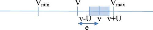
Appendix 2. Basic concepts of metrology in a sample of papers dealing with force and moment estimation, for active safety systems or stability enhancement systems
Table A1. Sample of papers dealing with force and moment estimation or dealing with vehicle states estimation for deriving forces and moments at the tyres. Analysis of reference that has been made in such papers on metrological concepts, like acceptable measurement range, uncertainty of the measurement, repeatability and reproducibility.
Appendix 3. Model data, mechanical model exploited in
Table