
 ?Mathematical formulae have been encoded as MathML and are displayed in this HTML version using MathJax in order to improve their display. Uncheck the box to turn MathJax off. This feature requires Javascript. Click on a formula to zoom.
Abstract
The article presents the experimental results of flow boiling of water in single rectangular microchannels. Three rectangular copper microchannels having the same hydraulic diameter (0.56 mm) and length (62 mm) but different aspect ratios (width/height, 0.5, 2.56, and 4.94) were investigated using de-ionized water as the working fluid. The experiments were conducted over the experimental range of mass flux 200–800 kg/(m2s), heat flux 4–1350 kW/m2 and inlet subcooling of ∼14 K. The results showed that the channel with smaller aspect ratio exhibited better heat transfer performance up to certain heat fluxes (∼480–500 kW/m2), whilst the effect of channel aspect ratio became insignificant for higher heat fluxes. The flow boiling patterns were observed and the main flow regimes were bubbly, slug, churn, and annular flow. Flow reversal was also observed that caused a periodic flow in the two microchannels having smaller aspect ratio. A comparison of the experimental results with widely used macro and micro-scale heat transfer correlations is presented. The macro-scale correlations failed to predict the experimental data while some micro-scale correlations could predict the data reasonably well.
Introduction
The rapid developments in miniaturization of novel electronic equipment and the improvements in their performance have resulted in a big challenge in their thermal management. The required heat dissipation rate from electronics and high power devices is expected to rise significantly. For example, Karayiannis and Mahmoud [Citation1] reported that in computer chips, the average heat flux is expected to reach 2–4.5 MW/m2 by 2026 with local hot spots exceeding these values. Higher heat fluxes occur in insulated gate bipolar transistor modules; the heat flux at the chip level can reach 6.5–50 MW/m2 [Citation1]. Tullius et al. [Citation2] reported that the heat dissipation rate in different applications could exceed 10 MW/m2. Accordingly, effective cooling schemes are needed to meet these huge heat fluxes. Flow boiling in microchannels is regarded as a promising solution for cooling such electronic equipment and high heat flux devices. This is based on the fact that flows with phase change can achieve high heat transfer rates and better axial temperature uniformity than single phase flow-based cooling schemes. However, the underlying physical phenomena of flow boiling heat transfer in micro scale are still not clear [Citation1]. There is little agreement among researchers on the effect of operating and geometrical parameters on the characteristics of flow boiling at micro scale. For example, some researchers [Citation3–5] studied the effect of channel geometry on flow boiling heat transfer characteristics and reported different conclusions. Yen et al. [Citation3] tested smooth Pyrex glass circular and square microchannels with the same hydraulic diameter (Dh = 0.21 mm) and concluded that the heat transfer coefficient was higher for the square microchannel. They attributed this to the sharp edges of the square microchannel, which behaved as effective nucleation sites that enhance the heat transfer rate. On the contrary, Tran et al. [Citation4] and Lin et al. [Citation5] did not report any significant differences in heat transfer coefficient between circular and rectangular channels. In the following paragraphs, a review is presented on flow boiling characteristics of water in microchannels. There is a large volume of work that used for example refrigerants, which have significant differences in thermo-physical properties compared to water. This difference in properties affects significantly the bubble dynamics and consequently the heat transfer rates, see Mahmoud and Karayiannis [Citation6]. However, studies using fluids other than water that are directly relevant to the work presented here are also included for completeness.
Kuznetsov and Shamirzaev [Citation7] investigated flow boiling of R-134a in a parallel copper rectangular channels of width 335 µm and height 930 µm (β = 0.36). The average roughness (Ra) of the bottom surface of the channel was 1 µm and the mass flux ranged from 200 to 600 kg/(m2s). It was found that the heat transfer coefficient is strongly affected by the heat flux up to xlocal = 0.5 and hence they concluded that nucleate boiling was the dominant heat transfer mechanism. Additionally, they reported that nucleate boiling was suppressed at high vapor qualities (xlocal > 0.5). The authors attributed this phenomenon to the existence of a very thin liquid film, and stated that the contribution of conduction through the liquid film could exceed the contribution of nucleate boiling in the case of nucleate boiling suppression. Yin and Jia [Citation8] studied bubble growth during flow boiling of deionized water in a single copper rectangular channel of 0.5 mm width and 1 mm height (β = 0.5) and length 100 mm at a fixed inlet sub-cooling of 77 K and mass flux 20 and 40 kg/(m2s). It was found that bubbles nucleate at the channel corners then grow while undergoing a change from spherical to elongated shape. Also, the bubble diameter (D) was found to obey a power law as D = ktn (slow rate) similar to conventional channels in the early stage of bubble development. k and n are empirical constants and t is time. In later stages, the bubble diameter was found to increase linearly as D = kt + n (faster rate). The boundary between the two stages (point at which the trend changes from power law to linear trend) was considered as the onset of the effect of channel confinement. In other words, the onset of bubble deformation was considered as a sign of the effect of channel confinement. Additionally, the local heat transfer coefficient was found to increase to a peak value at xlocal = 0.2 then it decreases rapidly with increasing vapor quality with a clear heat flux effect, i.e. the coefficient increased with increasing heat flux. In addition to that, the heat transfer coefficient decreased with increasing mass flux in the high quality region. They did not explain why the heat transfer coefficient decreased with increasing mass flux. The increase of the heat transfer coefficient to a peak value in the low vapor quality region was attributed to the presence of bubbly flow and the evaporation of the thin film in the confined and elongated bubble regime for xlocal = 0.1–0.3. They attributed the subsequent decrease in the heat transfer coefficient with vapor quality in the annular flow regime to the reduction in the evaporation rate due to the thinning of the liquid film along the channel. Their explanation seems to contradict expectations because as the liquid film becomes thinner the thermal resistance becomes lower and the heat transfer coefficient should increase with vapor quality.
Huh and Kim [Citation9] investigated flow boiling of water in a horizontal Polydimethylsiloxane microchannel of square cross sectional area 0.1 × 0.1 mm2 (β = 1). The mass flux ranged from 90 to 267 kg/(m2s) and the heat flux was varied from 200 to 500 kW/m2. It was found that the two-phase heat transfer was dominated by the nucleate boiling mechanism. However, the observed major flow pattern was similar to conventional annular flow. The authors stated that the flow boiling in the microchannel was characterized by the fast and long elongated slug bubbles grown from single bubbles due to the continuous supply of heat through a thin liquid film. They added that the conventional correlations did not provide reliable heat transfer coefficient predictions for different vapor quality values except under some limited conditions. Krishnan et al. [Citation10] studied the effect of orientation on flow boiling characteristics of deionized water in a micro gap channel of width 20 mm, depth 0.22 mm (β = 91) and length 30 mm at a mass flux range 193–911 kg/(m2s). The average surface roughness of the bottom surface was Ra = 1.73 µm and the inlet sub-cooling was kept fixed at 67 K. They tested four orientations namely: normal horizontal, inverted horizontal, vertical upward and vertical downward. It was found that orientation does not have a significant effect on the boiling curve and the critical heat flux for the range of their parameters.
Markal et al. [Citation11] studied the effect of aspect ratio on flow boiling characteristics of water in a silicon rectangular multi-microchannel heat sink with aspect ratio range 0.37–5 and hydraulic diameter 0.1 mm. The mass flux ranged from 151 to 324 kg/(m2s) and the inlet sub-cooling was 50 K. The results indicated that the effect of aspect ratio is not significant for aspect ratio range 0.37–1.27 and 2.7–5. On the contrary, there was a significant increase in the heat transfer coefficient when the aspect ratio was increased from 1.27 to 2.7. For the channels with aspect ratio (2.7–5), the boiling curve was steeper compared to channels with aspect ratio range 0.37–1.27, i.e. boiling occurs at much lower wall superheat (about 5 K compared to 30 K for channels with smaller aspect ratio). Additionally, it was observed that the heat transfer coefficient at one location near the channel exit decreased with increasing vapor quality (heat flux) for the channels with aspect ratio range 2.7–5 (shallow channels) which was not the case for the channels with smaller aspect ratio (deep channels). In other words, shallow channels promote the occurrence of partial dryout although they achieve better enhancements in the heat transfer rates. It was also found that the heat transfer coefficient increased with increasing mass flux and therefore this was considered as an indication of the dominance of convective boiling. Singh et al. [Citation12] investigated the effect of channel aspect ratio on flow boiling pressure drop using a single silicon microchannel having hydraulic diameter 0.142 mm, length 20 mm and aspect ratio range 1.24–3.75. The working fluid was water. It was shown that, for the same heat and mass flux, the pressure drop decreases with increasing aspect ratio (shallow channels) reaching a minimum value at β = 1.56 then increases with increasing aspect ratio. Candan et al. [Citation13] tested flow boiling characteristics of water in a single copper rectangular channel of hydraulic diameter 1.2 mm, 48 mm length and aspect ratio range 0.25–4. The average roughness Ra of the bottom surface of the channel was 0.086 µm. The mass flux ranged from 70 to 310 kg/(m2s) and the inlet sub-cooling was kept at 16 K. They reported that the best performance was achieved with β = 1 due to the presence of uniform liquid film at the sharp corners of square channels while the poorest performance occurred with β = 0.25 due to early local dryout. The heat transfer coefficient near the channel exit was found to increase with heat flux, mass flux and vapor quality and they concluded that the dominant heat transfer mechanism is nucleate boiling. Although their results do not exactly reflect the nucleate boiling characteristics, the authors observed that bubble nucleation is active in a large part of the channels, and the dominant flow patterns are bubbly/slug flow, which they related to nucleate boiling. Soupremanien et al. [Citation14] investigated the effect of the channel aspect ratio on the flow boiling heat transfer of Forane-365HX using two rectangular aluminum microchannels having the same hydraulic diameter and length (Dh = 1.4 mm, L = 83 mm) but different aspect ratio (β = 2.32 and 6.99). They reported that the flow boiling heat transfer coefficient is higher for the higher aspect ratio channel for low heat flux values whilst it was higher for the other channel at high heat fluxes. The authors attributed this to an earlier dryout occurrence in the channel having a higher aspect ratio. In another study, Fu et al. [Citation15] carried out an experimental study to examine the effect of channel aspect ratio on flow boiling heat transfer and critical heat flux characteristics of dielectric liquid HFE-7100 with parallel copper uniform and diverging microchannels (Dh = 1.12 mm, β = 0.17–2.2). They observed that the wall heat flux and the wall critical heat flux shows a peak value for β = 1. The authors attributed this behavior to the copious presence of liquid film around this microchannel corners. However, they continue to comment that for the same mass flux, the base critical heat flux increases monotonously with decreasing aspect ratio. This was due to the higher heat transfer area.
The above literature indicates that the effect of channel geometry on the flow boiling heat transfer coefficient is not clear. Additionally, some researchers reported that convective boiling is the dominant heat transfer mechanism for water while others reported the dominance of nucleate boiling. Thus, further experimental studies are needed to understand the effect of geometrical parameters and operating conditions on the dominant heat transfer mechanism. The article presents an experimental study on the effect of heat and mass flux on flow boiling heat transfer characteristics of deionized water using single copper microchannels of length 62 mm. Additionally, the effect of channel aspect ratio was also investigated. Flow visualization was also conducted along with the heat transfer measurements using high speed camera integrated with a microscope. The experimental data were used to assess existing heat transfer correlations.
Experimental setup and methodology
depicts a schematic diagram of the experimental facility. A detailed description can be found in [Citation16]. It consists of a liquid tank, a sub-cooler, a magnetically coupled gear pump (Micropump GA-T23, PFSB), a preheater, the test section, Data acquisition System (National Instruments), ultrasonic flow meter (Atrato 710-V20-D), a condenser and a chiller. Degassing was conducted by boiling the de-ionized water vigorously in the tank, before conducting the tests, until the difference between the temperature in the tank and the saturation temperature corresponding to the measured pressure inside the tank is ± 0.5 K. After the non-condensable gases were released to the ambient, the de-ionized water was delivered to the test section using the gear pump. The water temperature at the test section inlet was varied by adjusting the electric power to the preheaters located ahead of the test section. The data were collected after the system reaches steady state, i.e. very small fluctuations in the recorded temperature and pressure signals. The amplitude of fluctuations was 0.1 K, 0.06 K and 0.31 kPa for the fluid inlet, outlet and wall temperature and pressure drop, respectively.
Figure 1. (a) Schematic diagram of the experimental facility, (b) Top view of the test section (TS3). Dimensions in mm.
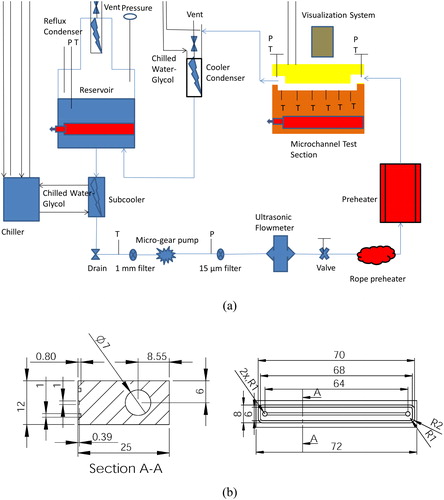
The test sections were cut on the top surface of an oxygen-free copper block using CNC machining. Three rectangular test sections were used in the current study and their dimensions are summarized in . The measured uncertainty of the channel dimensions is ± 0.002 mm and ± 0.1 mm for the channel height and width and channel length, respectively. In this case, the propagated uncertainty value for the channel hydraulic diameter can be calculated as ±0.32 − 0.49% and for the channel heat transfer area as ±0.19 − 0.25%. The average surface roughness (Ra) of the bottom surface of the microchannels was found to be 0.102 µm, 0.496 µm and 0.39 µm for TS1, TS2 and TS3, respectively. Note that using the average roughness only to characterize and understand the effect of surface microstructure may be misleading. This is because the cavity mouth diameter and the cavity depth are the most important surface parameters that can affect nucleation and the bubble ebullition cycle [Citation1, Citation17, Citation18].
Table 1. Dimensions of the microchannels in the current study.
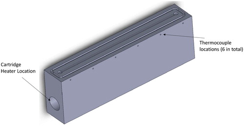
The test sections were heated using a cartridge heater inserted in the copper block in a direction parallel to the flow. The local axial wall temperatures were measured using six K-type thermocouples in the holes that were located 1.1 mm distance below the channel bottom, see . The copper block was inserted in a housing made of polycarbonate to reduce the heat loss. The top side of the copper block was covered with 10 mm thickness transparent polycarbonate plate for flow visualization. The pressure drop was measured directly between the channel inlet and outlet using a differential pressure transducer. All data were recorded at a frequency of 1 kHz for 3 min using the compact modular data acquisition system with Labview software. Flow patterns were observed with a Phantom high-speed, high-resolution camera which was located on top of the test section. The camera was integrated with a stereo microscope for better flow visualization.
Figure 2. Three-dimensional model of the test section.
Data reduction
The heat loss from the test section (Qloss) was estimated by applying an electric power (P) to the test section when there is no fluid inside. The temperature difference between the bottom wall and ambient was recorded for each heating power after attaining steady state. The applied power was then plotted versus this temperature difference and the data were fitted to obtain an equation to calculate the heat loss (Qloss) during single-phase and boiling experiments. The percentage of the heat loss varied from 5.2 to 9.2% over the experimental range. In this study, the top cover was assumed to be adiabatic and a uniform heat flux was assumed to be applied on all three sides of the channel. This assumption was adopted by past researchers in their data reduction process, e.g. [Citation7, Citation19–23].
The heat flux () was defined as:
(1)
(1)
where Aht is the heat transfer area, which is defined below as:
(2)
(2)
The local single-phase heat transfer coefficient (hsp(z)) and average Nusselt number (Nuav) are calculated as:
(3)
(3)
(4)
(4)
The channel wall temperature at the bottom surface for each axial location z (Tw(z)) was obtained using the one – dimensional heat conduction equation given by Eq. (5) below. Tf (z) is calculated by Eq. (6) below based on an energy balance assuming uniform heat flux boundary condition. Adopting the one – dimensional assumption to estimate the channel base temperature is also very common in literature, see for example refs. [Citation2, Citation3, Citation7, Citation10, Citation12, Citation19], where the assumption of linear temperature distribution versus the vertical distance was verified.
(5)
(5)
(6)
(6)
The single-phase fanning friction factor (fch) is calculated as:
(7)
(7)
In Eq. (7), the channel pressure drop (Δpch), the mass flux (G) and the channel hydraulic diameter (Dh) are calculated using EquationEqs. (8)–(10), respectively.
(8)
(8)
(9)
(9)
(10)
(10)
The overall pressure drop between the channel inlet and outlet plenums (Δpmeas) is measured directly using the differential pressure sensor. Δploss defined by Eq. (11) below, is the pressure loss due to the inlet and outlet manifolds and the sudden contraction and enlargement.
(11)
(11)
The flow enters and leaves the channel in a direction normal to the flow direction. Here, the values of loss coefficients K90, Kc and Ke are provided by refs. [Citation24, Citation25]. The fluid enters the channel as a sub-cooled liquid. Therefore, the channel is divided into a single-phase region and two-phase region. The single-phase region starts from the channel inlet to the location of zero thermodynamic quality with length Lsub. Thus, the length of the two-phase region (Lsat) becomes:
(12)
(12)
The length of the single-phase region (Lsub) is calculated iteratively using the following equations.
(13)
(13)
(14)
(14)
(15)
(15)
The values of the constant C, fFDRe and K (∞) in Eq. (15) are given in Shah [Citation25] for rectangular channels. The dimensionless length (L*sub) in Eq. (15) can be determined by Eq. (16) below. The fully-developed flow Poiseuille number (fFDRe) is given by Shah and London [Citation24] in Eq. (17) in the form of a function of the channel aspect ratio (β).
(16)
(16)
(17)
(17)
The local pressure in the two-phase part was assumed to decrease linearly with the axial length z and it can be calculated as:
(18)
(18)
where the net two-phase pressure drop across the channel is defined as:
(19)
(19)
The local two-phase heat transfer coefficient was defined as:
(20)
(20)
The local saturation temperature Tsat(z) in Eq. (20) is calculated based on the local pressure given by Eq. (18). The vapor quality can be determined by EquationEqs. (21)(21)
(21) and Equation(22)
(22)
(22) .
(21)
(21)
(22)
(22)
In the boiling experiments, the mass flux was kept constant and the heat flux was increased gradually in small intervals. The nominal inlet pressure was kept constant at 101 ± 15 kPa during the experiments by controlling the condenser temperature, i.e. adjust the cooling to the condenser. The propagated uncertainty analysis was conducted according to the method explained in [Citation26]. The uncertainty values were ±5.2–7.9% for the local two-phase heat transfer coefficient, ±1.23–9.4% for local vapor quality and ±0.82–10.9% for two-phase pressure drop. The experimental setup was validated using single-phase experiments. depicts the experimental single phase friction factor and average Nusselt number compared with conventional correlations for fully developed and developing flow for TS2 [Citation24, Citation27–30]. The applicability range and reported accuracy of the single-phase pressure drop and heat transfer correlations are summarized in . Similar figures were obtained for TS1 and TS3. The hydrodynamically developing flow theory predicted reasonably well the experimental friction factor data for all test sections with a Mean Absolute Error (MAE) of 3.5–12.4%. The experimental average Nusselt number data were predicted well by the thermally developing flow theory of Shah and London [Citation24] with a MAE range of 5.5–9.2% and is in agreement with previous work reported in [Citation27].
Figure 3. Single-phase validation of experimental procedure and measurements.
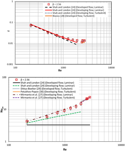
Table 2. Single-phase pressure drop and heat transfer correlations, range and MAE reported by the corresponding authors based on their data.
Results and discussion
Flow patterns
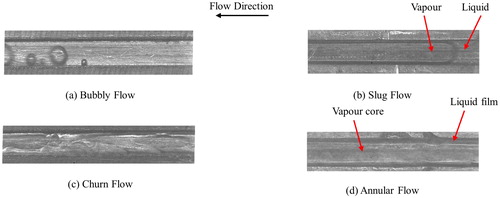
The flow patterns were captured at three locations (inlet, middle and outlet regions). Four flow patterns were observed along the channel namely: bubbly, slug, churn and annular flow, see . Flow reversal was also observed at certain operating conditions as will be discussed later. A transitional flow regime (bubbly/slug flow) was also visualized frequently between the bubbly flow and slug flow regimes. In this transitional regime, the bubbles grow to the channel width and form slug and elongated bubbles very rapidly as they move in the flow direction due to constant heat flux input. It is worth mentioning that bubbly and slug flow were dominant in the inlet region while annular flow was dominant at the outlet section of the channel.
Figure 4. Definition of the observed flow patterns in the current study. (a) Bubbly flow, (b) Slug flow, (c) Churn flow, and (d) Annular flow.
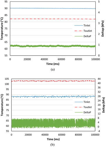
Flow reversal was observed in the present study at low mass fluxes at boiling incipience (low heat flux levels) and resulted in a case of periodic flow regime. During this regime, bubbly, slug, reverse flow, local-dryout and re-wetting stages occurred periodically with fluctuations in pressure drop and temperature signals, see . The occurrence of flow reversal may be attributed to the periodic expansion of the vapor slug to the upstream and downstream sides of the channel.
Figure 5. Fluctuations in fluid inlet and outlet temperature and pressure drop at G = 400 kg/(m2s) for TS2: (a) single phase flow with q” = 0 kW/m2, (b) During periodic flow, q” = 99.1 kW/m2.
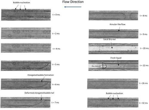
This periodic flow regime was reported by many researchers in literature [Citation11, Citation19, Citation20]. displays the periodic evolution of the flow patterns observed in this study for TS2 at G = 400 kg/(m2s) near the middle of the channel. The figure demonstrates that small bubbles nucleate at the channel corners at time designated as t = 0 ms while, the central region of the channel was in single-phase flow. After 5 ms, the growing bubble merged with the surrounding small bubbles and an elongated bubble was formed. The tail of this elongated bubble seems deformed (not in spherical shape), see (t= 6 ms). At t = 7 ms the picture shows also another bubble with a spherical head coming from the inlet region. This results in the formation of an elongated bubble which expands rapidly in the upstream and downstream sides of the channel. The nose of the bubble moves faster than the tail. This could be attributed to the partial blockage of the channel resulting from the rapid growth of the bubble, without actually departing from the nucleation site. Thus, the quantity of the liquid in the downstream side of the channel becomes smaller compared to the upstream side. Given that the heat flux is constant, this can result in a higher evaporation rate downstream of the bubble (thin liquid film with less thermal resistance). After 9 ms, the picture shows “annular-like” flow patterns but it is not annular flow. This pattern resulted from the coalescence of elongated bubbles. Moreover, this pattern remained in the channel for a time period and resulted in local-dryout as can be demonstrated at time 20 ms. Moreover, the figure at t = 20 ms shows that the central region of the channel is in dry-out condition, while there is a thin liquid film at the corners as indicated by the small arrows. It is interesting to note that, after 22 ms, fresh liquid enters and re-wetts the channel. The re-wetting interval took about 10 ms (from 22 ms to 32 ms), i.e. single phase liquid flow without any bubbles. After the re-wetting stage small bubbles were observed to nucleate near the channel corners again at time designated as t = 32 ms.
Figure 6. Sequence of flow images at the middle of the channel for periodic flow regime in the microchannel TS2 (β = 2.56) at q” = 99.15 kW/m2 and G = 400 kg/(m2s).
At higher mass fluxes (G = 600 kg/(m2s) and 800 kg/(m2s)), flow reversal and periodic flow regime were weak compared to that occurring at low mass fluxes due to the increase in the forward liquid inertia force. To verify this, the ratio of the evaporation momentum force and the inertia force is presented at different mass flux values under boiling incipience condition for TS2, see EquationEqs. (23)(23)
(23) and Equation(24)
(24)
(24) , [Citation31].
(23)
(23)
(24)
(24)
As seen in , the ratio is higher than unity for the mass fluxes 200 and 400 kg/(m2s) where the flow reversal and periodic flow were observed in the present study. On the other hand, for the higher mass fluxes that showed stable flow, the ratio decreased significantly and the ratio is less than unity which means that the inertia force becomes higher than the evaporative momentum force. Note that other forces such the shear force are not included in this force balance. The analysis herein is still useful giving an order of magnitude for the inertia and evaporation forces.
Table 3. The ratio of the evaporation momentum force and the inertia force for TS2 at boiling incipience.
These findings match those observed in earlier studies [Citation11, Citation19, Citation20, Citation32–35]. The rapid bubble growth pushes the liquid-vapor interface of the vapor slugs toward the upstream and downstream sides of the channel. Thus, it leads to back flow since the length of the microchannels is very small compared to conventional size channels. The flow patterns changed from single-phase flow to bubbly, slug, churn and annular flow with the increase in heat flux for all test sections.
Effect of aspect ratio on flow patterns
depict the effect of channel aspect ratio on flow patterns captured near the channel outlet section for G = 400 kg/(m2s). shows the effect of aspect ratio on the bubbly flow regime at nearly similar conditions. As seen in the figure, bubbly flow was not observed in TS1 at the outlet region. Bubbly flow was only observed at the middle region of the channel after boiling incipience at low heat flux levels. This may be attributed to the strong effect of channel confinement in TS1, which leads to bubble elongation and consequently the development of slug flow at the outlet section of the channel. demonstrates that bubbles nucleate and detach from the nucleation sites only at the channel corners for TS2 (β = 2.56). This is different compared to what is observed in TS3 (β = 4.94) where the bubbles nucleate and detach from nucleation sites on the bottom surface of the channel as well as the channel corners. The difference in the location of active nucleation sites between TS2 and TS3 could be attributed to (i) the difference in surface roughness and (ii) the area of bubble influence. In narrow channels, the local cooling due to the nucleating bubble starting in the corner may span the channel width. This could reduce the temperature of the bottom surface and confine nucleation only in the channel corners. On the contrary, in wide channels, the channel width is larger than the area of bubble influence. Thus, the local wall superheat may not be affected by the bubbles nucleating at the channel corners resulting in the formation of bubbles on the bottom surface. It is worth mentioning that channel corners favor bubble nucleation regardless of channel size.
Figure 7. Effect of channel aspect ratio on bubbly flow.
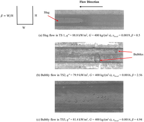
Figure 8. Effect of channel aspect ratio on slug flow.
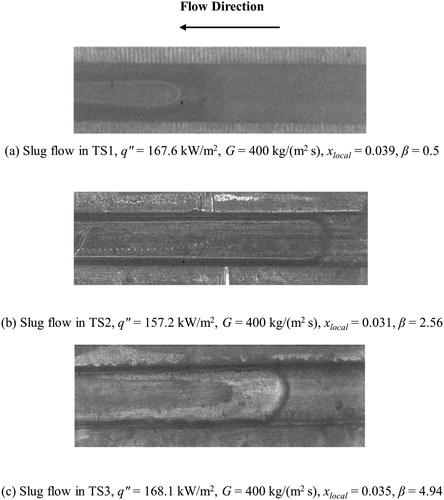
Figure 9. Effect of channel aspect ratio on churn flow.
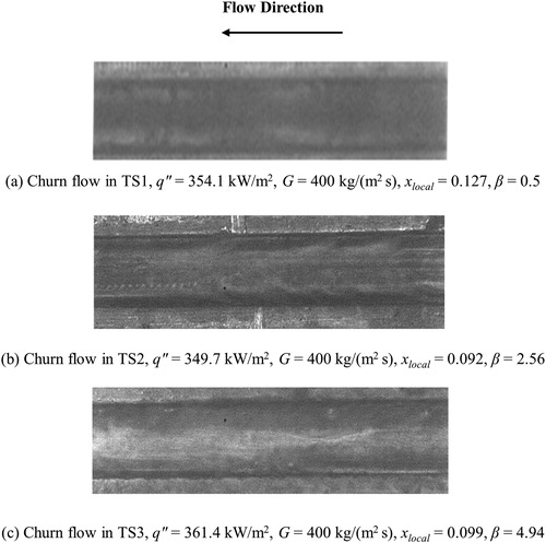
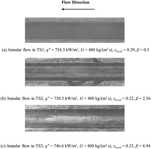
Figure 10. Effect of channel aspect ratio on annular flow.
In the literature, some researchers reported that slug flow appears immediately after boiling incipience when the channel size is too small. For example, Harirchian and Garimella [Citation36] for dielectric fluid (FC-77) did not observe bubbly flow in the two smallest microchannels (Dh = 0.16 and 0.307 mm) tested in their study whilst they reported bubbly flow in the larger microchannels (Dh = 0.4–0.749 mm). As mentioned above, slug flow appeared immediately after boiling incipience in TS1 near the channel outlet, i.e. as the aspect ratio decreases, the bubbles coalesce very rapidly and form elongated bubble (slug) due to the confined space.
As the heat flux was increased, the bubbles started to coalesce and became as large as the channel size resulting in the formation of slug flow in the three test sections, see . As the heat flux was increased further, the flow regime turned to churn flow and annular flow as seen in and , respectively. In the churn flow regime, the larger vapor bubbles become unstable and collapse. In this regime, the structure of the large elongated slugs and distorted vapor pockets alternated and resulted in chaotic motion and the liquid-vapor interface disappeared. The tail of the slug was no longer distinguishable properly at this condition. The characteristics of the churn flow were similar for all test sections. In annular flow, the liquid layer was present on the channel wall and the vapor flowed continuously at the center of the channel for all test sections.
It can be concluded from the above discussion that channel aspect ratio has an effect on the bubbly flow characteristics. For example, bubbly flow was not observed in the channel with the smallest aspect ratio (TS1, β = 0.5) at the outlet region, i.e. narrower channels did not support bubbly flow downstream the nucleate boiling region. Instead, the slug flow regime appeared immediately after boiling incipience at the outlet section although bubbles were observed in the upstream sections. On the other hand, isolated small bubbles were observed at the outlet region for the microchannel having the largest aspect ratio (β = 4.94) after boiling incipience. In TS2, the shape of the bubbles was elongated rather than isolated as in TS3. The reason for this might be the small aspect ratio of TS2 compared to TS3, which means that the confinement effect due to the side walls is important. The aspect ratio does not affect the other flows significantly.
Heat transfer results
Boiling curve
The boiling curve can be used to assess the heat transfer surfaces in terms of boiling incipience and nucleation, i.e. the slope of the curve can give an indication of nucleation. Boiling incipience can be detected from the Δptp-q” curve, q”-ΔTsub curve or htp-q” as the condition at which there is a sudden change from single phase values to two phase values, see ref. [Citation37]. It can also be detected by flow visualization using a high speed camera when the first bubble appears, see ref. [Citation38]. In the present study, the boiling incipience was detected from the conventional boiling curve (q”-ΔTsub) when there was a sudden change in the slope of the curve supported with flow visualization and fluctuations in pressure and temperature signals, see ref. [Citation16]. The fluctuations in pressure and temperature were negligible at zero heat flux while when boiling commenced the signals demonstrated large periodic fluctuations. This was considered as evidence of boiling incipience.
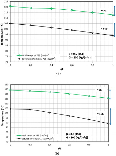
depicts the boiling curve for TS1, as an example, for one axial location z/L = 0.6 and different mass fluxes. The figure shows that, for all mass fluxes, the wall superheat at boiling incipience is between 3 and 5 K, with a clear change in slope at these values. At boiling incipience the wall superheat dropped slightly in all test sections and increased again with increasing heat flux. indicates also that the heat flux at the Onset of Nucleate Boiling (ONB) depends slightly on mass flux, e.g. it increased with increasing mass flux. However, for higher heat flux input (∼q” > 600 kW/m2) the mass flux effect on the boiling curves become weaker. These results agree with refs. [Citation19, Citation38, Citation39] who reported that the mass flux effect on the boiling curve is not very significant. Mahmoud [Citation38] analyzed the boiling curves in a vertical tube of D = 0.52 mm and concluded that the mass flux had no effect on the boiling curve, even at axial locations near the tube exit. The weak mass flux effect depicted in indicates that the heat transfer coefficient calculated as is lower for G = 800 kg/(m2s) compared to G = 200 kg/(m2s). The tendency of the heat transfer coefficient to decrease with increasing mass flux could be attributed to the increase in pressure gradient with increasing mass flux, which can affect the local saturation temperature. It is worth mentioning that the assumption of linear pressure drop along the channel adopted in the data reduction could result in some errors in the prediction of the local saturation temperature. depicts the temperature variation with axial location for the lowest and highest mass fluxes. As can be seen, the wall superheat increased significantly toward the exit as the mass flux was increased from 200 to 800 kg/(m2s). The heat flux used in the calculations was assumed to be uniformly distributed along the channel. These factors, high pressure drop, linear assumption of pressure drop and uniform heat flux, could possibly explain this result, i.e. decrease of the heat transfer coefficient with increasing mass flux. This is currently under investigation.
Figure 11. Boiling curve for TS1 (β = 0.5) at z/L = 0.6.
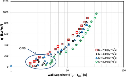
Figure 12. Wall and saturation temperature versus dimensionless axial distance for (a) G = 200 kg/(m2s) and (b) G = 800 kg/(m2s).
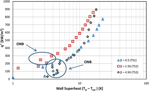
illustrates the effect of channel aspect ratio on the boiling curve for G = 800 kg/(m2s) at axial location z/L = 0.6. As can be seen from the figure, the ONB commences at similar wall superheat values for TS1 and TS3 [∼4–5 K]. On the contrary, TS2 starts boiling at slightly lower wall superheat [∼3 K]. However, the difference is not notable. The figure demonstrates also that after boiling incipience, the boiling curves of TS1 with β = 0.5 and TS3 with β = 4.94 merge into one curve up to a heat flux value of about 500 kW/m2 after which the two curves deviate with a larger slope for TS3, i.e. higher heat transfer rate. This means that the deepest and widest channels tested in this study exhibit similar behavior in the low heat flux region. On the contrary, the TS2 with β = 2.56 performed better in this low heat flux region compared to TS1 and TS3. In the high heat flux region, the behavior of TS2 approaches that of TS3. Closer flow visualization work, combined with among others an assessment of the surface characteristics (to include not only surface roughness but also possible number/size of cavities) are necessary to explain this result for these three aspect ratios. This behavior of the boiling curve has been also observed for other mass flux values (G = 200 kg/(m2s), G = 400 kg/(m2s) and G = 600 kg/(m2s)). Therefore, the effect of aspect ratio on the boiling curve has similar characteristics for all mass flux tests.
Figure 13. Effect of aspect ratio on boiling curve for G = 800 kg/(m2s) at z/L = 0.6.
Effect of heat flux, and channel aspect ratio on heat transfer coefficient
Effect of heat flux
depicts the effect of heat flux on the local heat transfer coefficient versus local vapor quality for TS1 at G = 200 kg/(m2s) and low to moderate heat flux levels while depicts the heat flux effect at high heat flux levels. The degree of inlet subcooling was 14 K. As seen in , for low to moderate heat fluxes (up to xlocal = 0.2), the heat transfer coefficient increased with increasing heat flux with little dependence on vapor quality. For each heat flux value, the heat transfer coefficient increased rapidly to a peak value at vapor quality near zero (boiling incipience). Beyond this point, the heat transfer coefficient had a slightly decreasing trend or remained almost constant with vapor quality for vapor quality 0.02 < xlocal < 0.2 where the flow regimes changed from bubbly/slug to churn and annular flows. The possible explanation of the constant trend of the heat transfer coefficient in the low quality region might be the presence of nucleating bubbles inside the thin liquid film even during churn and annular flow, see [Citation23]. Kandlikar and Balasubramanian [Citation39] investigated flow boiling of water in rectangular microchannels (Dh = 0.33 mm). They reported that the flow boiling heat transfer coefficient slightly decreased or remained constant with vapor quality. They observed nucleating bubbles at the walls during liquid flow and in the thin liquid film during churn and annular flow. They attributed the trend of flow boiling heat transfer coefficient versus vapor quality to these nucleating bubbles.
Figure 14. Effect of low and moderate heat flux input and local quality on the local heat transfer coefficient at 200 kg/(m2s) for TS1.
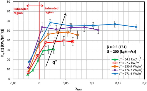
Figure 15. Effect of high heat flux input on the local heat transfer coefficient for the TS1 at 200 kg/(m2s); (a) versus local vapor quality and (b) versus axial distance.
The above results reveal that the heat transfer coefficient increased with heat flux and was independent of vapor quality at low and medium heat flux inputs or vapor quality 0.02 < xlocal < 0.2. These results are in agreement with the results of [Citation22, Citation23, Citation40], which showed that the heat transfer coefficient increased with heat flux for low and moderate heat flux input or low vapor quality region (xlocal < 0.2) and slightly decreased or remained constant with vapor quality for xlocal > 0.2. On the other hand, some other researchers reported that the heat transfer coefficient decreased sharply with vapor quality in the saturated region up to xlocal ≈ 0.7 (the highest vapor quality in their study), see [Citation19, Citation41, Citation42]. These researchers attributed this trend of heat transfer coefficient to partial dry-out due to rapid bubble growth or the possible high pressure drop in micro-scale channels. In this study, the heat transfer coefficient also decreased sharply with local vapor quality but only at high mass flux conditions, i.e. G > 600 kg/(m2s).
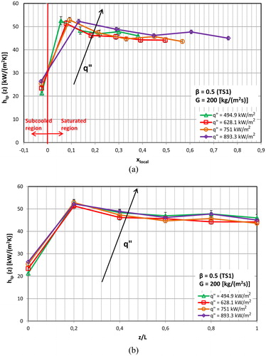
demonstrates that for high heat flux levels, the effect of heat flux on the local heat transfer coefficient versus local vapor quality and dimensionless axial distance is insignificant. The corresponding flow regimes were annular or churn flow at these high heat flux condition.
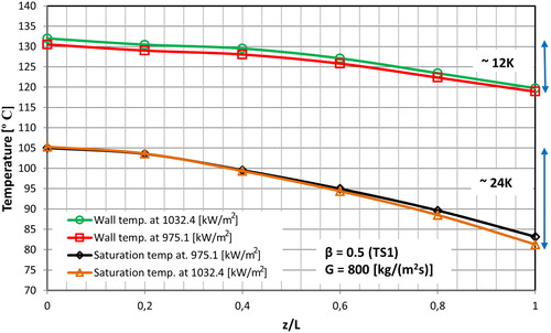
The abovementioned behavior may be explained as follows: the observed elongated slugs seemed stagnant for a period of time before the fresh liquid pushes them downstream. Thus, at low and medium heat flux input, it is probable that the elongated slugs leave the channel before the liquid film dries out. The clear heat flux effect observed at the low and medium heat flux input in could be attributed to this process during the nucleation cycle. At high heat flux input partial dry-out might be the reason of the insignificant heat flux effect on the heat transfer coefficient. Partial dry-out was captured in the channels using the high-speed camera where a vapor blanket was observed near the middle and outlet of the channels during the tests. However, no significant increase in the wall temperature was observed at this condition. Moreover, the heat transfer coefficient slightly decreased with vapor quality for all test sections at high heat flux input. At higher mass fluxes, the heat transfer coefficient declined sharper than at the lower mass flux conditions. In order to understand the reason of the decreasing trend of the local heat transfer coefficient with local vapor quality, the variation in saturation temperature with dimensionless axial channel distance is plotted in for the last three applied heat fluxes and for the TS1 at 800 kg/(m2s). The local saturation temperature values were calculated based on the local pressures. The local pressure values were determined using an assumption that the flow boiling pressure drop decreases linearly along the microchannels. As seen in , the saturation temperature decreases at a higher rate compared to the wall temperature with increasing distance from the inlet. Thus, the difference between the wall temperature and saturation temperature increase toward to the outlet at the fixed value of mass flux and heat flux, giving a smaller calculated heat transfer coefficient.
Figure 16. Saturation temperature variation (24 K) and wall temperature variation (12 K) along the channel axial distance for the TS1 at 800 kg/(m2s) at two different heat fluxes.
Effect of channel aspect ratio
depicts the effect of channel aspect ratio on the local heat transfer coefficient plotted versus local vapor quality at G = 200 kg/(m2s) for these channels, which have the same hydraulic diameter and length (Dh = 0.56 mm, L = 62 mm). The channels with smaller aspect ratio exhibited better heat transfer performance for low/medium heat flux input up to local quality 0.2. However, at high heat flux input, the channel aspect ratio has little effect on the local heat transfer coefficient. A very small effect at high heat flux input can be seen in until the middle region of the channel (z/L ≤ 0.6). However, after that, the heat transfer coefficient curves appeared to merge together for the microchannels. These results were also obtained for other mass flux conditions (G = 400, 600 and 800 kg/(m2s)). In order to see this trend clearly, the average heat transfer coefficient versus heat flux for the microchannels is plotted for the 200 kg/(m2s) and 600 kg/(m2s) mass fluxes in . The channels having smaller aspect ratio have a better heat transfer performance up to ∼480–500 kW/m2 heat flux input. The channel aspect ratio has no effect on the heat transfer coefficient beyond these heat flux values. The results of are in agreement with those presented in the above subsections where the heat transfer coefficient increased with heat flux at low and medium heat flux input but became constant at high heat flux input. Since the controlling heat transfer mechanism was found to be nucleate boiling at low and medium heat flux input, a possible explanation for the better heat transfer performance of the smaller aspect ratio channel (the deep channel) might be the stronger effect of stratification (higher buoyancy effects). This could possibly allow the bubbles to detach from the surface and flow in the upper cross section of the channel leaving a thicker liquid film at the bottom surface and channel corners. In other words, the bottom surface of the channel is always wetted in deep channels. Therefore, deeper channels exhibited better heat transfer performance in the nucleate boiling region. At higher heat flux input, the nucleate boiling may be replaced with thin film evaporation and hence, the heat transfer coefficient became less sensitive to channel aspect ratio. As discussed in the introduction section, the effect of aspect ratio is very complex. Markal et al. [Citation11] reported that the heat transfer coefficient increased with increasing heat flux in deep channels while it decreases with heat flux in shallow channels. On the contrary, Candan et al. [Citation13] reported that the deep channels exhibited poor heat transfer performance due to the occurrence of dryout. Recently, Al-Zaidi et al. [Citation43] reported that, for HFE-7100, the local heat transfer coefficient increases with increasing aspect ratio for all tested conditions. It is clear from the above that the effect of aspect ratio on the local and average heat transfer coefficient is not clear and needs further investigation. This should include a range of aspect ratio of channels having the same surface roughness and hydraulic diameter. These studies should include different fluids, since fluid properties can affect flow patterns and heat transfer mechanisms and subsequently the aspect ratio effect.
Figure 17. Effect of aspect ratio on the local heat transfer coefficient for G = 200 kg/(m2s); (a) versus xlocal at low heat flux input, (b) versus xlocal at high heat flux input, (c) versus z/L at low heat flux input, (d) versus z/L at high heat flux input.
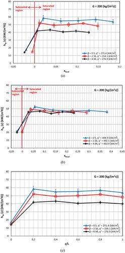
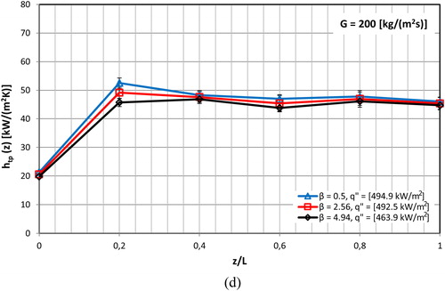
Figure 18. Effect of aspect ratio and heat flux on the average heat transfer coefficient for the three test sections; (a) at G = 200 (kg/m2s) and (b) at G = 600 (kg/m2s).
Comparison of the data with flow boiling heat transfer correlations
The flow boiling heat transfer coefficient data were compared with four widely used conventional scale and nine widely used micro-scale correlations. The evaluation of the correlations was conducted using the percentage of the data (α) within ±30% error bars and the MAE. In the literature, many researchers [Citation40, Citation44–46] compared their data with conventional scale correlations and reported that these correlations generally under-predicted or over-predicted the heat transfer coefficient at micro-scale level. This might be attributed to the fact that the conventional scale correlations do not consider the microscale effects such as surface tension and confinement. Since the surface tension force becomes dominant as the diameter decreases, this effect needs to be considered in micro-scale systems. summarizes the results of the comparisons with these correlations [Citation47–50].
Table 4. MAE and the percentage of data within ± 30% error bands for conventional scale correlations.
As seen in the , the conventional-scale correlations could not predict well the experimental heat transfer coefficients for all test sections. Accordingly, nine micro-scale correlations were selected to compare with the experimental data in the current study [Citation22, Citation46, Citation51–56]. These correlations were developed for water. However, Lazarek and Black [Citation55] and Mahmoud and Karayiannis [Citation56] (correlations 1 and 2) which were developed based on refrigerants are also included. provides the comparisons of the experimental data with micro scale correlations.
Table 5. MAE and the percentage of data within ± 30% error bands for micro-scale correlations.
As demonstrated in the results summarized in , the micro-scale correlations performed better than the conventional-scale correlations. The correlations of Sun and Mishima [Citation53], Li and Wu [Citation54], Mahmoud and Karayiannis [Citation56] (correlations 1 and 2) predicted fairly well the experimental data for the tested microchannels and the current experimental range. The applicability range and reported accuracy of the conventional-scale and micro-scale boiling heat transfer correlations are summarized in .
Table 6. Conventional-scale and micro-scale boiling heat transfer correlations, range and MAE reported by the corresponding authors based on their data.
Conclusions
Flow boiling heat transfer was investigated in three copper microchannel test sections having the same length (62 mm) and hydraulic diameter (0.561 mm) but different aspect ratio (β = 0.5, 2.56 and 4.94). The effect of heat flux, vapor quality and channel aspect ratio on flow patterns and heat transfer coefficient results were presented and discussed. The results were also compared with some existing heat transfer correlations. The key concluding remarks can be summarized as follows:
Four flow patterns were observed along the channel namely; bubbly, slug, churn and annular flow. The flow patterns could change periodically from single phase flow to bubbly, slug, churn and annular flow. This was observed in all test sections except TS3.
The channel aspect ratio affects the bubbly flow regime. Bubbly flow was not observed in the channel with the smallest aspect ratio (β = 0.5) at the outlet section. The bubbles were dispersed and small in the channel with the largest aspect ratio (TS3, β = 4.94). As the aspect ratio was decreased to 2.56, the bubbles became elongated due to confinement.
The local heat transfer coefficient increased with heat flux and was independent of the local vapor quality for low and medium heat fluxes. However, the effect of heat flux was insignificant at high heat fluxes.
The heat coefficient increased as the channel aspect ratio decreased up to heat flux values about 480–500 kW/m2. For higher heat fluxes, the channel aspect ratio had no effect on the heat transfer coefficient. Further research is recommended to clarify the effect of aspect ratio.
The conventional scale correlations could not predict the experimental heat transfer results.
The micro-scale correlations proposed by Sun and Mishima [Citation53], Li and Wu [Citation54] and Mahmoud and Karayiannis [Citation56] predicted the experimental results reasonably well.
| Nomenclature | ||
| = | cross sectional area, m2 | |
| = | heat transfer area, m2 | |
| = | thermocouple distance from the channel surface, m | |
| = | specific heat, J/(kg K) | |
| = | correction factor | |
| = | diameter, m | |
| = | hydraulic diameter, m | |
| = | inlet plenum diameter, m | |
| = | outlet plenum diameter, m | |
| = | evaporation momentum force, N | |
| = | inertia force, N | |
| = | single-phase fanning friction factor | |
| = | apparent laminar friction factor | |
| = | apparent turbulent friction factor | |
| = | fully developed friction factor | |
| = | correction factor for friction factor | |
| = | mass flux, kg/(m2s) | |
| = | single-phase heat transfer coefficient, W/(m2 K) | |
| = | two-phase heat transfer coefficient, W/(m2 K) | |
| = | channel height, m | |
| = | specific enthalpy, J/(kg K) | |
| = | specific enthalpy at the inlet, J/(kg K) | |
| = | liquid specific enthalpy, J/(kg K) | |
| = | enthalpy of vaporization, J/kg | |
| = | empirical constant | |
| = | liquid thermal conductivity, W/(m K) | |
| = | copper thermal conductivity, W/(m K) | |
| = | 90° turn loss coefficient | |
| = | expansion loss coefficient | |
| = | contraction loss coefficient | |
| = | pressure drop number | |
| = | length, m | |
| = | dimensionless length | |
| = | single-phase length, m | |
| = | dimensionless single phase length | |
| = | two-phase length, m | |
| = | mean absolute error | |
| = | mass flow rate, kg/s | |
| = | empirical constant | |
| = | average Nusselt number | |
| = | onset of nucleate boiling | |
| = | inlet pressure, Pa | |
| = | saturation pressure, Pa | |
| = | power, W | |
| = | Prandtl number | |
| Q | = | heat input, W |
| = | heat loss, W | |
| = | heat flux, W/m2 | |
| = | average roughness, µm | |
| = | Reynolds number | |
| = | modified Reynolds number | |
| = | wall temperature, K | |
| = | fluid temperature, K | |
| = | inlet temperature, K | |
| = | thermocouple temperature, K | |
| = | saturation temperature, K | |
| = | time, s | |
| = | channel fluid velocity, m/s | |
| = | plenum fluid velocity, m/s | |
| = | channel width, m | |
| = | local vapor quality | |
| = | axial distance, m | |
| Greek symbols | ||
| = | percentage of data within ± 30% error | |
| = | channel aspect ratio, W/H | |
| = | channel pressure drop, Pa | |
| = | pressure losses, Pa | |
| = | measured pressure drop, Pa | |
| = | single-phase pressure drop, Pa | |
| = | two-phase pressure drop, Pa | |
| = | wall superheat, K | |
| = | liquid density, kg/m3 | |
| = | vapor density, kg/m3 | |
Acknowledgement
The first author acknowledges the support provided by the Turkish Higher Research Council.
Additional information
Funding
Notes on contributors

Mehmed Rafet Özdemir
Mehmed Rafet Özdemir graduated from the Mechanical Engineering Department, Faculty of Engineering, Marmara University, Turkey. He was employed as a research assistant in the same department since 2009. He obtained his master's degree from Sabancı University in the field of two-phase heat transfer and fluid flow in microtubes in 2010. He joined Prof. Karayiannis’s research group, as a Ph.D. student, at Brunel University London, UK, in 2012 and got his Ph.D. in 2016 in single-phase flow and flow boiling of water in rectangular metallic microchannels. Currently, he is an assistant professor in the Mechanical Engineering Department, Faculty of Engineering, Marmara University, Turkey. His research interests include micro/nano scale heat transfer, boiling heat transfer, microfluidic systems, phase change materials, and heat transfer improvements.

Mohamed M. Mahmoud
Mohamed M. Mahmoud graduated in 1998 from the Mechanical Engineering Department, Faculty of Engineering, Zagazig University, Egypt. He was employed as an assistant lecturer in the Environmental Engineering Department in the same university since 1999. He received his M.Sc. in 2004 in the field of biomass combustion from Zagazig University. He joined Prof. Karayiannis’s research group, as a Ph.D. student, at Brunel University, London, UK, in 2007 and got his Ph.D. in 2011 in two-phase flow boiling heat transfer in small-to microdiameter tubes. He worked as a lecturer in the Environmental Engineering Department from 2011 to 2018. Currently, he is an associate professor in the Environmental Engineering Department, Zagazig University, Egypt. His research interests include flow boiling heat transfer in microsystems, solid waste/biomass thermal treatment for biofuel production, and thermal desalination systems.

Tassos G. Karayiannis
Tassos G. Karayiannis studied at the City University London and the University of Western Ontario. He started his career as a researcher at Southampton University and later as a British Technology Group Researcher at City University. Subsequently he worked at London South Bank University and joined Brunel University London in 2005 where he is now professor of Thermal Engineering and Leader of the Energy Efficient & Sustainable Technologies Theme. He has carried out fundamental and applied research in a number of heat transfer related topics including natural convection and renewable energy. He has been involved with two-phase flow and heat transfer for over 30 years. Initially, he worked on the enhancement of pool boiling and condensation processes using high intensity electric fields (electrohydrodynamic enhancement of heat transfer). In parallel, he carried out extensive experimental work in pool boiling heat transfer with plane and enhanced surfaces. He has also been very actively involved with research in flow boiling in small to micro tubes and micro-multi-channels. This work involves fundamental studies as well as research leading to the design of high heat flux integrated thermal management systems. He chairs the Int. Conf. on Micro and Nanoscale flows. He is a Fellow of the EI and the IMechE, the Chairman of the UK National Heat Transfer Committee and a UK Representative on the Assembly for Int. Heat Transfer Conferences.
References
- T. G. Karayiannis, and M. M. Mahmoud, “Flow boiling in microchannels: fundamentals and applications,” Appl. Therm. Eng, vol. 115, pp. 1372–1397, Mar. 2017. DOI: 10.1016/j.applthermaleng.2016.08.063.
- J. F. Tullius, R. Vajtal, and Y. Bayazıtoglu, “A review of cooling in microchannels,” Heat Transf. Eng, vol. 32, no. 7-8, pp. 527–541, Jun. 2011. DOI: 10.1080/01457632.2010.506390.
- T.-H. Yen, M. Shoji, F. Takemura, Y. Suzuki, and N. Kasagi, “Visualization of convective boiling heat transfer in single microchannels with different shaped cross-sections,” Int. J. Heat Mass Transf., vol. 49, no. 21-22, pp. 3884–3894, Oct. 2006. DOI: 10.1016/j.ijheatmasstransfer.2005.12.024.
- T. N. Tran, M. W. Wambsganss, and D. M. France, “Small circular-and rectangular-channel boiling with two refrigerants,” Int. J. Multiph. Flow, vol. 22, no. 3, pp. 485–498, Jun. 1996. DOI: 10.1016/0301-9322(96)00002-X.
- S. Lin, P. A. Kew, and K. Cornwell, “Flow boiling of refrigerant R141B in small tubes,” Chem. Eng. Res. Des., vol. 79, no. 4, pp. 417–424, May 2001. DOI: 10.1205/026387601750282346.
- M. M. Mahmoud and T. G. Karayiannis, “Flow boiling in mini to micro diameter channels,” In Encyclopedia of Two Phase Heat Transfer and Flow IV, vol. 3, 1st ed., J. R. Thome, Eds. Lausanne, Switzerland: World Scientific, 2018, pp. 233–301.
- V. V. Kuznetsov and A. S. Shamirzaev, “Flow boiling heat transfer of refrigerant R-134a in copper microchannel heat sink,” Heat Transf. Eng., vol. 37, no. 13-14, pp. 1105–1113, Feb. 2016. DOI: 10.1080/01457632.2015.1111103.
- L. Yin and L. Jia, “Confined bubble growth and heat transfer characteristics during flow boiling in microchannel,” Int. J. Heat Mass Transf., vol. 98, pp. 114–123, Jul. 2016. DOI: 10.1016/j.ijheatmasstransfer.2016.02.063.
- C. Huh and M. H. Kim, “Pressure drop, boiling heat transfer and flow patterns during flow boiling in a single microchannel,” Heat Transf. Eng., vol. 28, no. 8-9, pp. 730–737, 2007. DOI: 10.1080/01457630701328213.
- R. A. Krishnan, K. R. Balasubramanian, and S. Suresh, “Experimental investigation of the effect of heat sink orientation on subcooled flow boiling performance in a rectangular microgap channel,” Int. J. Heat Mass Transf., vol. 120, pp. 1341–1357, May 2018. DOI: 10.1016/j.ijheatmasstransfer.2017.12.133.
- B. Markal, O. Aydin, and M. Avci, “Effect of aspect ratio on saturated flow boiling in microchannels,” Int. J. Heat Mass Transf., vol. 93, pp. 130–143, Feb. 2016. DOI: 10.1016/j.ijheatmasstransfer.2015.10.024.
- S. G. Singh, A. Kulkarni, S. P. Duttagupta, B. P. Puranik, and A. Agrawal, “Impact of aspect ratio on flow boiling of water in rectangular microchannels,” Exp. Therm. Fluid Sci., vol. 33, no. 1, pp. 153–160, Oct. 2008. DOI: 10.1016/j.expthermflusci.2008.07.014.
- A. Candan, B. Markal, O. Aydin, and M. Avci, “Saturated flow boiling characteristics in single rectangular minichannels: effect of aspect ratio,” Exp. Heat Transf., vol. 31, no. 6, pp. 1–21, Apr. 2018. DOI: 10.1080/08916152.2018.1463305.
- U. Soupremanien, S. L. Person, M. Favre-Marinet, and Y. Bultel, “Influence of the aspect ratio on boiling flows in rectangular mini-channels,” Exp. Therm. Fluid Sci., vol. 35, no. 5, pp. 797–809, Jul. 2011. DOI: 10.1016/j.expthermflusci.2010.06.014.
- B.-R. Fu, C.-Y. Lee, and C. Pan, “The effect of aspect ratio on flow boiling heat transfer of HFE-7100 in a microchannel heat sink,” Int. J. Heat Mass Transf., vol. 58, no. 1-2, pp. 53–61, Mar. 2013. DOI: 10.1016/j.ijheatmasstransfer.2012.11.050.
- M. R. Özdemir, M. M. Mahmoud, and T. G. Karayiannis, “Flow boiling heat transfer in a rectangular copper microchannel,” J. Therm. Eng., vol. 2, no. 3, pp. 761–773, Jul. 2016. DOI: 10.18186/jte.01281.
- Y.-T. Mu, L. Chen, Y.-L. He, Q.-J. Kang, and W.-Q. Tao, “Nucleate boiling performance evaluation of cavities at mesoscale level,” Int. J. Heat Mass Transf., vol. 106, pp. 708–719, Mar. 2017. DOI: 10.1016/j.ijheatmasstransfer.2016.09.058.
- J. P. McHale and S. V. Garimella, “Nucleate boiling from smooth and rough surfaces–part 2: analysis of surface roughness effects on nucleate boiling,” Exp. Therm. Fluid Sci., vol. 44, pp. 439–455, Jan. 2013. DOI: 10.1016/j.expthermflusci.2012.08.005.
- E. Galvis and R. Culham, “Measurements and flow pattern visualizations of two-phase flow boiling in single channel microevaporators,” Int. J. Multiph. Flow, vol. 42, pp. 52–61, Jun. 2012. DOI: 10.1016/j.ijmultiphaseflow.2012.01.009.
- K. Balasubramanian, M. Jagirdar, P. S. Lee, C. J. Teo, and S. K. Chou, “Experimental investigation of flow boiling heat transfer and instabilities in straight microchannels,” Int. J. Heat Mass Transf., vol. 66, pp. 655–671, Nov. 2013. DOI: 10.1016/j.ijheatmasstransfer.2013.07.050.
- E. M. Fayyadh, M. M. Mahmoud, K. Sefiane, and T. G. Karayiannis, “Flow boiling heat transfer of R134a in multi microchannels,” Int. J. Heat Mass Transf., vol. 110, pp. 422–436, Jul. 2017. DOI: 10.1016/j.ijheatmasstransfer.2017.03.057.
- T.-W. Lim, S.-S. You, J.-H. Choi, and H.-S. Kim, “Experimental investigation of heat transfer in two-phase flow boiling,” Exp. Heat Transf., vol. 28, no. 1, pp. 23–26, Jul. 2015. DOI: 10.1080/08916152.2013.803173.
- P.-S. Lee and S. V. Garimella, “Saturated flow boiling heat transfer and pressure drop in silicon microchannel arrays,” Int. J. Heat Mass Transf., vol. 51, no. 3-4, pp. 789–806, Feb. 2008. DOI: 10.1016/j.ijheatmasstransfer.2007.04.019.
- R. K. Shah and A. L. London, Laminar Flow Forced Convection in Ducts: A Source Book for Compact Heat Exchanger Analytical Data. Cambridge, MA, USA: Academic Press, 1978.
- R. K. Shah, “A correlation for laminar hydrodynamic entry length solutions for circular and noncircular ducts,” J. Fluids Eng., vol. 100, no. 2, pp. 177–179, Jun. 1978. DOI: 10.1115/1.3448626.
- H. W. Coleman and W. G. Steele, Experimentation, Validation, and Uncertainty Analysis for Engineers. Hoboken, NJ, USA: John Wiley & Sons, 2018.
- M. Mirmanto, D. B. R. Kenning, J. S. Lewis, and T. G. Karayiannis, “Pressure drop and heat transfer characteristics for single-phase developing flow of water in rectangular microchannels,” J. Phys. Conf. Series, vol. 395, pp. 1–13, Jan. 2012. DOI: 10.1088/1742-6596/395/1/012085.
- H. Blasius, “Das aehnlichkeitsgesetz bei reibungsvorgängen in flüssigkeiten,” in Mitteilungen über Forschungsarbeiten auf dem Gebiete des Ingenieurwesens, vol. 131, 1st ed., Heidelberg, Berlin: Springer, 1913. pp. 1–41.
- F. W. Dittus and L. M. K. Boelter, “Heat transfer in automobile radiators of the tubular type,” Int. Commun. Heat Mass Transf., vol. 12, no. 1, pp. 3–22, Jan.-Feb. 1985. DOI: 10.1016/0735-1933(85)90003-X.
- B. S. Petukhov, “Heat transfer and friction in turbulent pipe flow with variable physical properties,” Adv. Heat Transf., vol. 6, pp. 503–564, Jan. 1970. DOI: 10.1016/S0065-2717(08)70153-9.
- H. J. Lee, D. Y. Liu, and S. Yao, “Flow instability of evaporative micro-channels,” Int. J. Heat Mass Transf., vol. 53, no. 9-10, pp. 1740–1749, Apr. 2010. DOI: 10.1016/j.ijheatmasstransfer.2010.01.016.
- G. Hetsroni, A. Mosyak, E. Pogrebnyak, and Z. Segal, “Explosive boiling of water in parallel micro-channels,” Int. J. Multiph. Flow, vol. 31, no. 4, pp. 371–392, Apr. 2005. DOI: 10.1016/j.ijmultiphaseflow.2005.01.003.
- H. J. Lee, D. Y. Liu, Y. Alyousef, and S. Yao, “Generalized two-phase pressure drop and heat transfer correlations in evaporative micro/minichannels,” J. Heat Transf., vol. 132, no. 4, pp. 1–9, Feb. 2010. DOI: 10.1115/1.4000861.
- G. Hetsroni, A. Mosyak, Z. Segal, and E. Pogrebnyak, “Two-phase flow patterns in parallel micro-channels,” Int. J. Multiph. Flow, vol. 29, no. 3, pp. 341–360, Mar. 2003. DOI: 10.1016/S0301-9322(03)00002-8.
- G. Hetsroni, A. Mosyak, E. Pogrebnyak, and Z. Segal, “Periodic boiling in parallel micro-channels at low vapor quality,” Int. J. Multiph. Flow, vol. 32, no. 10-11, pp. 1141–1159, Oct.-Nov. 2006. DOI: 10.1016/j.ijmultiphaseflow.2006.06.005.
- T. Harirchian and S. V. Garimella, “Effects of channel dimension, heat flux, and mass flux on flow boiling regimes in microchannels,” Int. J. Multiph. Flow, vol. 35, no. 4, pp. 349–362, Apr. 2009. DOI: 10.1016/j.ijmultiphaseflow.2009.01.003.
- M. Piasecka and M. E. Poniewski, “Hysteresis phenomena at the onset of subcooled nucleate flow boiling in microchannels,” Heat Transf. Eng., vol. 25, no. 3, pp. 44–51, 2004.
- M. M. Mahmoud, “Flow boiling of R134a in vertical mini-diameter tubes,” Ph.D. dissertation, Dept. of Mech. And Aeros. Eng., Brunel University London, London, UK, 2011.
- S. G. Kandlikar and P. Balasubramanian, “An experimental study on the effect of gravitational orientation on flow boiling of water in 1054 × 197μm parallel minichannels,” J. Heat Transf., vol. 127, no. 8, pp. 820–829, Feb. 2005. DOI: 10.1115/1.1928911.
- M. E. Steinke and S. G. Kandlikar, “An experimental investigation of flow boiling characteristics of water in parallel microchannels,” J. Heat Transf., vol. 126, no. 4, pp. 518–526, Aug. 2004. DOI: 10.1115/1.1778187.
- E. Sobierska, R. Kulenovic, R. Mertz, and M. Groll, “Experimental results of flow boiling of water in a vertical microchannel,” Exp. Therm. Fluid Sci., vol. 31, no. 2, pp. 111–119, Nov. 2006. DOI: 10.1016/j.expthermflusci.2006.03.022.
- W. Qu and I. Mudawar, “Flow boiling heat transfer in two-phase micro-channel heat sinks-II. Annular two-phase flow model,” Int. J. Heat Mass Transf., vol. 46, no. 15, pp. 2773–2784, Jul. 2003. DOI: 10.1016/S0017-9310(03)00042-5.
- A. H. Al-Zaidi, M. M. Mahmoud, and T. G. Karayiannis, “Flow boiling of HFE-7100 in multi-microchannels: aspect ratio effect,” presented at the 6th Micro and Nano Flows Conf., Atlanta, USA, Sep. 9, 2018.
- A. Koşar, C.-J. Kuo, and Y. Peles, “Boiling heat transfer in rectangular microchannels with reentrant cavities,” Int. J. Heat Mass Transf., vol. 48, no. 23-24, pp. 4867–4886, Nov. 2005. DOI: 10.1016/j.ijheatmasstransfer.2005.06.003.
- S. Basu, S. Ndao, G. J. Michna, Y. Peles, and M. K. Jensen, “Flow boiling of R134a in circular microtubes—part I: study of heat transfer characteristic,” J. Heat Transf., vol. 133, no. 5, pp. 1–9, DOI: 10.1115/1.4003159.
- W. Yu, D. M. France, M. W. Wambsganss, and J. R. Hull, “Two-phase pressure drop, boiling heat transfer, and critical heat flux to water in a small-diameter horizontal tube,” Int. J. Multiph. Flow, vol. 28, no. 6, pp. 927–941, Jun. 2002. DOI: 10.1016/S0301-9322(02)00019-8.
- M. M, Shah. “Chart correlation for saturated boiling heat transfer: equations and further study,” presented at the Semi-annual meeting of the American Society of Heating, Ref., and Air Cond. Eng, Houston, USA, Jan. 24, 1982.
- K. E. Gungor and R. H. S. Winterton, “Simplified general correlation for saturrated flow boiling and comparison of correlation with data,” Chem. Eng. Res. Dev., vol. 65, no. 2, pp. 148–156, Feb. 1987.
- S. G. Kandlikar, “A general correlation for saturated two-phase flow boiling heat transfer inside horizontal and vertical tubes,” J. Heat Transf., vol. 112, no. 1, pp. 219–228, Feb. 1990. DOI: 10.1115/1.2910348.
- Z. Liu and R. H. S. Winterton, “A general correlation for saturated and subcooled flow boiling in tubes and annuli, based on a nucleate pool boiling equation,” Int. J. Heat Mass Transf., vol. 34, no. 11, pp. 2759–2766, Nov. 1991. DOI: 10.1016/0017-9310(91)90234-6.
- S. G. Kandlikar and P. Balasubramanian, “An extension of the flow boiling correlation to transition, laminar, and deep laminar flows in minichannels and microchannels,” Heat Transf. Eng, vol. 25, no. 3, pp. 86–93, Aug. 2004. DOI: 10.1080/01457630490280425.
- J. Lee and I. Mudawar, “Two-phase flow in high-heat-flux micro-channel heat sink for refrigeration cooling applications: part II—heat transfer characteristics,” Int. J. Heat Mass Transf., vol. 48, no. 5, pp. 941–955, Feb. 2005. DOI: 10.1016/j.ijheatmasstransfer.2004.09.019.
- L. Sun and K. Mishima, “Evaluation analysis of prediction methods for two-phase flow pressure drop in mini-channels,” Int. J. Multiph. Flow, vol. 35, no. 1, pp. 47–54, Jan. 2009. DOI: 10.1016/j.ijmultiphaseflow.2008.08.003.
- W. Li and Z. Wu, “A general correlation for evaporative heat transfer in micro/mini-channels,” Int. J. Heat Mass Transf., vol. 53, nos. 9-10, pp. 1778–1787, Apr. 2010. DOI: 10.1016/j.ijheatmasstransfer.2010.01.012.
- G. M. Lazarek and S. H. Black, “Evaporative heat transfer, pressure drop and critical heat flux in a small vertical tube with R-113,” Int. J. Heat Mass Transf., vol. 25, no. 7, pp. 945–960, Jul. 1982. DOI: 10.1016/0017-9310(82)90070-9.
- M. M. Mahmoud and T. G. Karayiannis, “Heat transfer correlation for flow boiling in small to micro tubes,” Int. J. Heat Mass Transf., vol. 66, pp. 553–574, Aug. 2013. DOI: 10.1016/j.ijheatmasstransfer.2013.07.042.