
 ?Mathematical formulae have been encoded as MathML and are displayed in this HTML version using MathJax in order to improve their display. Uncheck the box to turn MathJax off. This feature requires Javascript. Click on a formula to zoom.
Abstract
The goal of this research study is to examine, through the finite element method, the efficiency of using two-dimensional (2D) functionally graded materials (FGMs) in lowering the elastic/thermoelastic stresses acting on cylinders. In 2D-FGMs, the properties are assumed to vary in the radial and tangential directions simultaneously, which is rarely investigated in the literature. The cylinder is subjected to asymmetric inner normal traction with/without asymmetric thermal loading. For the considered case studies, results revealed that 2D-FGMs is beneficial compared to the conventional grading. In case of considering mechanical load only, the tangential stress declines by almost 39%. Similarly, accounting for thermomechanical load resulted in radical falls for the tangential and axial stresses by around 63% and 61%, respectively. Accordingly, the von Mises stress declines dramatically with different values allowing for safe load escalation, and enhancing the cylinder’s durability. Finally, no certain values for the used tangential function’s parameters are preferred to have maximum reduction of stresses under all working circumstances, which necessitates performing optimization.
1. Introduction
Functionally graded materials (FGMs) are extensively used in many engineering applications due to their sophisticated properties. Many authors investigated the behaviors of different functionally graded (FG) structures, such as plates, cylinders, and discs. For plates, Cong et al. [Citation1], for example, showed that the porosity had significant impacts on the thermomechanical buckling and post-buckling of FG cylinder (FGCs). Kouider et al. [Citation2] examined the effects of the volume fraction, geometrical parameters, and heterogeneity index on the bending and free vibration responses of FG sandwich plates. Others were concerned with the fracture of such structures (e.g., see Refs. [Citation3, Citation4]).
Regarding FGCs, many parameters were investigated under different load types (mechanical, thermal, electrical, magnetic, etc.) and conditions (symmetric, asymmetric), see for instance Refs. [Citation5–7]. For example, Tokovyy and Ma [Citation8] examined the performance of heterogeneous 1D-FGCs (1D: one-dimensional) subjected to partial thermal/mechanical loading with material properties radially graded. In addition, Batra and Nie [Citation9] used the polar form of the Fourier expansion and the method of Frobenius series to solve the differential equations of eccentric hollow FGCs. An exponential grading model was used by Loghman et al. [Citation10], as well, while scrutinizing the performance of FGCs subjected to nonsymmetrical magneto-thermomechanical loads. Furthermore, the decelerating behaviors of multilayer 1D-FGCs under thermoelastic loads were explored while considering the materials’ properties temperature dependency [Citation11]. Analogous analyses could be found studying the behaviors of 1D-FG discs [Citation12–15].
On a related front, researchers and industry seek lowering the stresses that encounter any mechanical structure to raise its lifetime, durability, safety level, and loading capacity. This also reduces the failure probability. Such goals could be achieved through different means that include but not limited to: optimization of some parameters Citation16–18, modifying the microstructure to yield a new material with desired properties [Citation19] that includes higher strength [Citation20], or developing two-dimensional (2D: two-dimensional) FGMs [Citation21, Citation22]. This article is concerned with the later method, where a property becomes dependent on two directions. This method is rarely examined in contrast to the large number of articles discussing 1D-FG structures. For 2D-FGMs, to name just a few, Nemat-Alla [Citation23] showed that they yielded improved performance than 1D-FGMs. Researches on 2D-FGMs are easily found in the Cartesian coordinates, see for instance Refs. [Citation21, Citation24, Citation25]. However, in polar coordinates, limited numbers considered it as a combination between both the radial and axial directions [Citation22, Citation26–30]. On the contrary, extremely rare articles were devoted to considering the variation with respect to the radial and tangential directions, see for example Ref. [Citation31, Citation32].
In view of the aforementioned comprehensive literature review, the goal of this article is to examine the effectiveness of using 2D-FGMs in alleviating the stresses encountering FGCs, compared to the traditional 1D-FGCs. The properties would vary in both the radial and tangential directions simultaneously. In addition, a finite element (FE) scheme is built to solve the differential equations. Two examples are presented: one with mechanical load only, and the other includes a thermomechanical load. For each example, the idea of applying 2D-FGMs is presented, and its associated results are discussed.
2. Problem formulation
Using polar coordinates (
), a stationary cylinder with inner and outer radii
and
respectively, is considered. The mechanical equilibrium equations in the radial and tangential directions are written as [Citation33]:
(1)
(1)
(2)
(2)
where a comma denotes partial differentiation.
and
(
and
) are the radial, circumferential, axial, and shear stresses (strains), respectively, which are evaluated via the constitutive equations (Hooke’s law) as follows [Citation34]:
(3)
(3)
with
(4)
(4)
(5)
(5)
where
is the thermal expansion coefficient,
is the temperature field (considering
as a reference temperature),
and
are the radial, tangential, and axial displacements, respectively. For consistency, it should be noted that the natural shearing strain (
) is the one used here, and it is equal to half of the engineering shear strain. Besides, for an isotropic material, EquationEq. (6)
(6)
(6) lists the materials’ stiffness constants (
and
) that are dependent on
(elastic constant) and
(Poisson’s ratio).
(6)
(6)
In terms of it is dependent on the thermal conductivity (
), and is obtained through solving the steady-state heat conduction equation in the 2D polar coordinates [Citation31]:
(7)
(7)
3. Finite element formulation
The finite element method (FEM) is widely used in modeling the behaviors of complicated problems in structural mechanics since it is known for its powerfulness and robustness. So, a FE scheme is developed through Matlab software to obtain
and
The domain is discretized using the eight-node (
) isoparametric 2D elements with three degrees of freedom (
and
) at each node. In FEM,
and
are approximately related to the corresponding nodal values through introducing number of shape functions
[Citation35]:
(8)
(8)
where
is the element
shape function at the
node.
Afterward, the standard Galerkin’s procedures are followed to obtain the following symbolic FE equation [Citation35]: where
represents the global stiffness matrix,
includes both of
and
and
is the external force vector. In more detail, the FE discretized equation for a system composed of total number of elements
is:
(9)
(9)
with
and
are the
element stiffness matrix and force vector, respectively. They are determined as follows:
(10)
(10)
where
is the element’s domain such that
is part of the boundary with specified tractions
and
is the thermal conductivity matrix. Also,
is the strain–displacement matrix, and
is the gradient matrix [Citation36]. These integrations are executed using the gauss quadrature method with
integration points within the element.
At this stage, the vector can easily obtained (
). Then, strains and stresses are calculated directly through the standard steps of FEM at the gauss points within the element after applying the proper boundary conditions, and then extrapolated to the nodes, where they are averaged based on a node’s location [Citation36].
4. Results and discussion
In this study, the results published by Li and Liu [Citation37] are regenerated to benchmark the accuracy of the developed FE Matlab code. In Ref. [Citation37], a stationary cylinder with under plane strain conditions (
) was investigated. The power-law model was selected to describe the gradation of some properties [Citation37]:
(11)
(11)
where
is a generic material property, and
is the heterogeneity index that the impacts of its variation were extensively examined in prior studies (e.g., see Refs. [Citation38–41]). Also, the two subscripts
and
refer to the property at
and
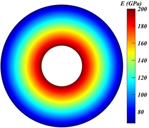
respectively. Li and Liu [Citation37] only proposed that
was varying according to EquationEq. (11)
(11)
(11) , with
and
( shows its distribution), while
and
was kept constant at
Figure 1. Contour plot for the distribution of using EquationEq. (11)
(11)
(11) .
For loading, the inner circumference was subjected to a sinusoidal normal traction: where
is the pressure amplitude, and
is the normal traction coefficient. Whereas, the cylinder’s outer edge was kept free of stress.
Regarding FEM, different number of elements along the radial and tangential directions was tested. After checking the mesh dependency, a great agreement is found to occur at (
and
elements in
and
directions, respectively), as depicted in where dimensionless (normalized) stresses are plotted. It should be noted that, henceforth, any stress component is divided by
to be normalized.
Figure 2. Dimensionless stresses distribution from the current study and Ref. [Citation37]. and
are plotted at
and
is plotted at
![Figure 2. Dimensionless stresses distribution from the current study and Ref. [Citation37]. σ¯r and σ¯θ are plotted at θ=0°, and τ¯rθ is plotted at θ=+45°.](/cms/asset/3faf6099-d441-469c-b190-de2a1bb2ca06/uths_a_2151960_f0002_b.jpg)
Then, using the same example, the idea of applying the principle of 2D-FGMs is examined to mitigate the stresses through the cylinder. In other words, would be a function in both
and
This idea has been rarely investigated in the literature as shown previously in Section 2. Mathematically, this is to be accomplished by implementing a known function
into EquationEq. (11)
(11)
(11) . Such function can take any formula, for instance, exponential [Citation31], trigonometric/polynomial [Citation32], etc. Here, the focus would be directed toward the trigonometric function: cosine, such that:
(12)
(12)
where the angular (frequency) coefficient
or
[Citation32], and
is the shifting (phase) angle that is to be investigated, and its selected values
Therefore, EquationEq. (11)
(11)
(11) becomes as follows after being multiplied by
[EquationEq. (12)
(12)
(12) ]:
(13)
(13)
where
is the modified property in the
and
directions. However, the nature of the cosine function would yield negative values of any property and escalates the positive value; hence, comparing results would not be reasonable. Thus, the following modification is proposed to keep
within the limits (
and
):
(14)
(14)
To make sure that there is no confusion occurs for the reader, presents, for instance, the variation of at
and 1 with different values of
where the harmonic pattern of the
function appears clearly.
Figure 3. Contour plots for using EquationEq. (14)
(14)
(14) .
At the beginning, the impacts of while
taking either the values of
and
are studied. Using EquationEq. (11)
(11)
(11) produces the contours depicted in with
and
It should be mentioned that, henceforth, subscripts max and min are used to refer to a quantity’s upper and lower values, respectively.
Figure 4. Dimensionless stress contours based on FEM solution for 1D-FGC. (a) Dimensionless radial stress, (b) dimensionless tangential stress, and (c) dimensionless shear stress.
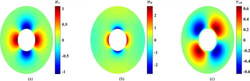
Enhanced results are obtained upon applying EquationEq. (14)(14)
(14) . The stresses’ contours for the selected values of
are presented in –Citation8. Evidently, the three stress components experienced different rates of reduction. However,
is the component that witnessed the significant drop compared to
and
Figure 5. Dimensionless stress contours for (a) Dimensionless radial stress, (b) dimensionless tangential stress, and (c) dimensionless shear stress.

For nearly
reduction is applicable at
(). This percentage declines if another value of
is chosen. However, at such instant (
),
showed an increase in the decline percentage hitting
at
as depicted in . Regarding
its upper and lower values almost remained static around a value of
which resembles a moderate decline. For example, in , both of them declined by nearly
at
This percentage approached
at
for
as shown in .
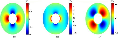
Figure 6. Dimensionless stress contours for (a) Dimensionless radial stress, (b) dimensionless tangential stress, and (c) dimensionless shear stress.
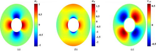
Figure 7. Dimensionless stress contours for (a) Dimensionless radial stress, (b) dimensionless tangential stress, and (c) dimensionless shear stress.
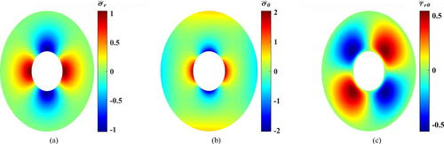
Then, when it comes to it can be stated that 2D-FGMs are absolutely advantageous. Numbers reveal that at
(),
went down steeply by
compared to the value of 1D-FGMs. Conversely, according to it declined moderately by
at
Similarly, at
it is depicted in that
and
declined significantly by approximately
and
respectively.
Figure 8. Dimensionless stress contours for (a) Dimensionless radial stress, (b) dimensionless tangential stress, and (c) dimensionless shear stress.
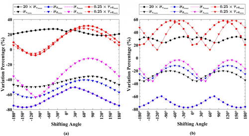
Furthermore, presents the reduction values occurring in the extreme values of each stress component at and
at different values of
Generally, it is found that there are no differences obtained when the sign of
changes as
has a similar harmonic pattern to the only present load. Also, in this case of loading, the use of
() produced larger reductions than
().
Figure 9. Percentages of stresses reduction at different values of for
(a)
and (b)
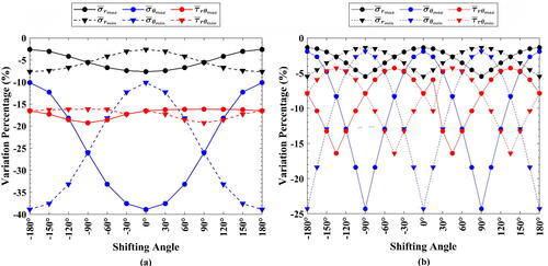
It can be stated that all the stress values witnessed different percentages of reduction. Since has higher value compared to
and
the focus would be directed toward it. If a designer chooses
(), a reduction of nearly
and
is applicable for
and
respectively. Since,
therefore,
is the cylinder’s load limit decisive parameter if considered individually. However, the small reduction in
is critical in most composites since metals have limited tensile strength compared to the huge compressive strength of ceramics that necessitates higher reduction in
In contrast, depicts that a compromise (
reduction) is applicable between the two percentages at
which is similar to predictions concluded from at
and
where a decline by almost
is attainable. Such points can be considered as the optimum points.
Based on the aforementioned results, it can be stated that using 2D-FGMs would significantly mitigate stresses allowing for load escalation. To make sure that this advantage always happens, the second example is presented, where thermomechanical loading is present. The following material properties are considered in addition to the previously mentioned ones with
and
[Citation42]. In addition, the following boundary conditions are used:
(15)
(15)
where
is the reference temperature, and
is the temperature’s coefficient.
presents the resulting temperature profile and stresses, for the 1D-FGC at
and
At this stage, another comparing parameter is introduced: the von Mises stress (
) that is calculated according to EquationEq. (16)
(16)
(16) [Citation43]. In the dimensionless form, it becomes:
(16)
(16)
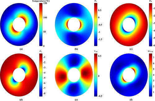
Figure 10. Resulting contours of the thermoelastic problem of 1D-FGC (). (a) Temperature, (b) dimensionless radial stress, (c) dimensionless tangential stress, (d) dimensionless axial stress, (e) dimensionless shear stress, and (f) dimensionless von Mises stress.
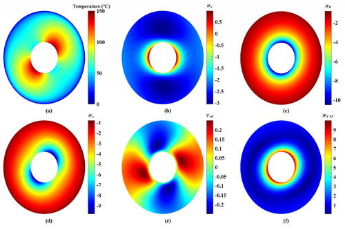
shows that varied between
and
and
stood at approximately
Also, the upper and lower limits of
leveled off at
Such results resemble a confirmation of the previous studies that
has noteworthy influences on the cylinder’s performance [Citation14, Citation44].
For 2D-FGMs, only (
and
) and
(
and
) are presented. The resulting temperature profiles are shown in –Citation14a. It is seen that there are significant differences in their distributions as they are interconnected with
Nevertheless, no impacts on the maximum and minimum
are seen since they are controlled by EquationEq. (15)
(15)
(15) , and no heat generation is present in EquationEq. (7)
(7)
(7) . But, it can be grasped that
in almost all regions tends to decrease except a small zone around the inner circumference. Consequently, profound effects are expected to encounter the stresses’ readings that capitalize on
Figure 11. Resulting contours of the thermoelastic problem of 2D-FGC with (a) Temperature, (b) dimensionless radial stress, (c) dimensionless tangential stress, (d) dimensionless axial stress, (e) dimensionless shear stress, and (f) dimensionless von Mises stress.
These induced stresses are plotted in –Citation14. It can be figured out that the usage of 2D-FGMs brought about drastic reductions in
and
Until this juncture, 2D-FGMs are far better than 1D-FGMs. Two tiny drawbacks are noticed. First, the maximum tensile
tends to slightly grow. Second, at certain values of
shows small rise. Nevertheless, the declines in
and
substantially outweigh those increases, which have negligible impacts on
In numbers, the values of witnessed slight growths. Conversely,
which is critical than
dropped significantly. For instance, in , it reached
at
and
that resembles about
of the value of the 1D-FGC. Likewise,
and
experienced substantial plunges. For example, at
and
(), they decreased by around
and
respectively. Despite that,
is still the serious one since it has larger absolute value compared to
Generally, for the selected values of
and
the decline percentage for
is confined between the previous percentage (
) and about half of it (
) (
and
). Similar behaviors are noticed for
In , for instance, the critical value of
went down by
if compared to the value at
shown in . This percentage rose reaching nearly
at
and
().
Figure 12. Resulting contours of the thermoelastic problem of 2D-FGC with (a) Temperature, (b) dimensionless radial stress, (c) dimensionless tangential stress, (d) dimensionless axial stress, (e) dimensionless shear stress, and (f) dimensionless von Mises stress.
Figure 13. Resulting contours of the thermoelastic problem of 2D-FGC with (a) Temperature, (b) dimensionless radial stress, (c) dimensionless tangential stress, (d) dimensionless axial stress, (e) dimensionless shear stress, and (f) dimensionless von Mises stress.
Figure 14. Resulting contours of the thermoelastic problem of 2D-FGC with (a) Temperature, (b) dimensionless radial stress, (c) dimensionless tangential stress, (d) dimensionless axial stress, (e) dimensionless shear stress, and (f) dimensionless von Mises stress.
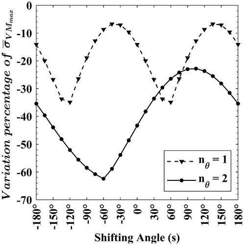
Such declines are considerably beneficial for raising the working loads and avoiding the occurrence of plasticity (failure) as appears in the reduction of (–Citation14f). It is evident that there are variations in the values of
based on
and
Using
with
yielded a decline in
by
(). It grew to almost
if
is switched to
(). Moreover, nearly two-thirds of that two values are applicable when
prevails with
() and
(), respectively.
Furthermore, presents the variations’ percentages occurring in each stress component at different values of at
and
respectively. First, it is seen that the sign of
yields dissimilar results in contrast to the previous case (mechanical load only). Second, the change in
is negligible if compared to the change of
Third, in , except at
(
), the upper and lower values of
experienced gigantic rises. Despite that, these numbers are tricky since they are less than unity. For example, at
and
(),
increased slightly from
to
Fourth, considering
brought about considerable declines in
which is more important than
since
Though the latter also witnessed massive drops, it can be neglected as they are fractions of one.
Figure 15. Variation’s percentage for each stress component for the thermoelastic problem of 2D-FGC with (a)
and (b)
Finally, since as well as
have the largest absolute values compared to other stress values, the change in
is considerably influenced by their variation. In , it can be deduced that
declined with different ranges despite the often misguiding growth of
and parts of
This decline hits almost
at
and
At that instant as shown in ,
grew by approximately
and
fell by
Moreover, the use of
produced the largest decrease for
(
) at
Nearly half of that value is the most applicable reduction percentage if
is used. That shows that
is more advantageous than
Figure 16. Maximum value of the dimensionless von Mises stress () reduction’s percentage.
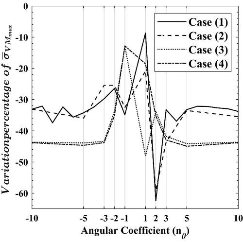
However, until now, the analyses in the study are restricted to or
This forms the foundation of the next part, where different values of
are examined, i.e.,
and
Four cases are explored at
In this part, along with the variation of
the values of
and
are altered and listed in .
Table 1. The pertinent numerical values of some parameters used while investigating different values of of 2D-FGC under thermomechanical loading conditions.
To avoid redundancy of results, only the variation of is presented in lieu of all the stress components. concludes that it is not always ensured to have
to attain the greatest reduction in
In case Equation(1)
(1)
(1) ,
produced the larger reduction in
(
) compared to the other values. This matches the patterns of the loads, where
In the second case, also,
is preferable despite changing
to
and keeping
By moving to the third case, it is seen that
is better and yielded
drop in
From these three cases, it can come to a mind that having
would produce improved
But, this is not constantly true, and this is proven in the fourth case, where
The favorable
is found to be at
This stark disagreement in such case with the three previous cases initiates due to the difference in both
and
Therefore, it can be understood that they with
and
have strategic roles in determining the ideal value of
to be used.
Figure 17. Variation of with
using different values of
and
5. Conclusion
In this study, a FE scheme was developed to check the efficiency of using 2D-FGMs in alleviating the elastic/thermoelastic stresses of FGCs. The power-law model was used to describe materials’ property variation radially, and it was modified to make properties dependent on both the radial and tangential directions concurrently.
Interpreting results showed the beneficial role of considering 2D-FGMs in reducing most of the stress components through the cylinder, which allows for raising the load limits safely. Eminent findings upon applying 2D-FGMs are listed below:
The tangential stress has the upper hand in determining the behaviors of cylinders. In the second place comes the axial stress that arises in plane strain conditions.
In case of mechanical loading: the radial, tangential, and shear stress components experienced declines in their values.
In case of thermomechanical loading: the radial and shear stresses experienced variations in their readings. Conversely, other stresses decreased significantly. However, a decline in the von Mises stress was achieved with substantial values.
Temperature in many regions of the cylinder tended to decline when the tangential variation of the thermal conductivity was considered, and this was the major cause for the variation of stresses.
The sign of the shifting angle almost had no impact in the case of mechanical loading. In contrast, it had a great role when both thermal and mechanical loads were present together.
The angular coefficient had significant impacts on the stresses’ variation.
Eventually, different percentages of stresses’ reductions are to be obtained if the gradation function is changed with its parameters (i.e., heterogeneity (grading) index). Therefore, it is recommended to optimize the angular coefficient and the shifting angle to obtain the global optimum of the stress components. This would be compulsory in case of complex loading and mixed boundary conditions. However, if 2D-FGMs are used without optimizing its associated parameters, inevitable drops of the stresses would occur.
Data availability
The raw/processed data required to reproduce these findings cannot be shared at this time as the data also forms part of an ongoing study.
Disclosure statement
The authors declared no potential conflicts of interest with respect to the research, authorship, and/or publication of this article.
Additional information
Funding
References
- P. H. Cong, et al., “Nonlinear thermomechanical buckling and post-buckling response of porous FGM plates using Reddy’s HSDT,” Aerosp. Sci. Technol., vol. 77, pp. 419–428, 2018. DOI: 10.1016/j.ast.2018.03.020.
- D. Kouider, et al., “An original four-variable quasi-3D shear deformation theory for the static and free vibration analysis of new type of sandwich plates with both FG face sheets and FGM hard core,” Steel Compos. Struct., vol. 41, no. 2, pp. 167–191, 2021. DOI: 10.12989/scs.2021.41.2.167.
- L. Guo, et al., “The interface crack problem for a functionally graded coating-substrate structure with general coating properties,” Int. J. Solids Struct., vol. 146, pp. 136–153, 2018. DOI: 10.1016/j.ijsolstr.2018.03.025.
- S. Huang, et al., “The interface crack problem under steady heat flux for a functionally graded coating-substrate structure with general coating properties,” Theor. Appl. Fract. Mech., vol. 109, pp. 102675, 2020. DOI: 10.1016/j.tafmec.2020.102675.
- M. Jabbari, M. Meshkini, and M. R. Eslami, “Mechanical and thermal stresses in FGPPM hollow cylinder due to radially symmetric loads,” J. Pressure Vessel Technol., vol. 138, no. 1, pp. 2938–2946, 2016. DOI: 10.1115/1.4031372.
- M. Jabbari, M. Meshkini, and M. R. Eslami, “Nonaxisymmetric mechanical and thermal stresses in FGPPM hollow cylinder,” J. Pressure Vessel Technol., vol. 134, no. 6, pp. 1–25, 2012. DOI: 10.1115/1.4007034.
- J. Jafari Fesharaki, et al., “Two-dimensional solution for electro-mechanical behavior of functionally graded piezoelectric hollow cylinder,” Appl. Math. Model., vol. 36, no. 11, pp. 5521–5533, 2012. DOI: 10.1016/j.apm.2012.01.019.
- Y. V. Tokovyy and C.-C. Ma, “Analytical solutions to the planar non-axisymmetric elasticity and thermoelasticity problems for homogeneous and inhomogeneous annular domains,” Int. J. Eng. Sci., vol. 47, no. 3, pp. 413–437, 2009. DOI: 10.1016/j.ijengsci.2008.10.005.
- R. C. Batra and G. J. Nie, “Analytical solutions for functionally graded incompressible eccentric and non-axisymmetrically loaded circular cylinders,” Compos. Struct., vol. 92, no. 5, pp. 1229–1245, 2010. DOI: 10.1016/j.compstruct.2009.10.022.
- A. Loghman, M. Nasr, and M. Arefi, “Nonsymmetric thermomechanical analysis of a functionally graded cylinder subjected to mechanical, thermal, and magnetic loads,” J. Therm. Stresses, vol. 40, no. 6, pp. 765–782, 2017. DOI: 10.1080/01495739.2017.1280380.
- A. M. Eldeeb, Y. M. Shabana, and A. Elsawaf, “Investigation of the thermoelastoplastic behaviors of multilayer FGM cylinders,” Compos. Struct., vol. 276, pp. 114523, 2021. DOI: 10.1016/j.compstruct.2021.114523.
- M. Hosseini, M. Shishesaz, and A. Hadi, “Thermoelastic analysis of rotating functionally graded micro/nanodisks of variable thickness,” Thin-Walled Struct., vol. 134, pp. 508–523, 2019. DOI: 10.1016/j.tws.2018.10.030.
- P. Nayak, S. Bhowmick, and K. N. Saha, “Elasto-plastic analysis of thermo-mechanically loaded functionally graded disks by an iterative variational method,” Eng. Sci. Technol. Int. J., vol. 23, no. 1, pp. 42–64, 2020. DOI: 10.1016/j.jestch.2019.04.007.
- A. M. Eldeeb, Y. M. Shabana, and A. Elsawaf, “Influences of angular deceleration on the thermoelastoplastic behaviors of nonuniform thickness multilayer FGM discs,” Compos. Struct., vol. 258, pp. 113092, 2021. DOI: 10.1016/j.compstruct.2020.113092.
- A. M. Eldeeb, Y. M. Shabana, and A. Elsawaf, “Thermo-elastoplastic behavior of a rotating sandwich disc made of temperature-dependent functionally graded materials,” J. Sandwich Struct. Mater., vol. 23, no. 5, pp. 1761–1783, 2021. DOI: 10.1177/1099636220904970.
- Y. M. Shabana and A. Elsawaf, “Nonlinear multi-variable optimization of layered composites with nontraditional interfaces,” Struct. Multidisc. Optim., vol. 52, no. 5, pp. 991–1000, 2015. DOI: 10.1007/s00158-015-1292-2.
- Y. M. Shabana, et al., “Stresses minimization in functionally graded cylinders using particle swarm optimization technique,” Int. J. Pressure Vessels Piping, vol. 154, pp. 1–10, 2017. DOI: 10.1016/j.ijpvp.2017.05.013.
- A. M. Eldeeb, Y. M. Shabana, and A. Elsawaf, “Particle swarm optimization for the thermoelastic behaviors of functionally graded rotating nonuniform thickness sandwich discs,” Arab. J. Sci. Eng., pp. 1–13, 2022. DOI: 10.1007/s13369-022-07351-x.
- S. Zhou and Q. Li, “Microstructural design of connective base cells for functionally graded materials,” Mater. Lett., vol. 62, no. 24, pp. 4022–4024, 2008. DOI: 10.1016/j.matlet.2008.05.058.
- Y. Su, et al., “Influence of composition gradient variation on the microstructure and mechanical properties of 316 L/Inconel718 functionally graded material fabricated by laser additive manufacturing,” J. Mater. Process. Technol., vol. 283, pp. 116702, 2020. DOI: 10.1016/j.jmatprotec.2020.116702.
- Nemat-Alla, M. K. I. E. Ahmed, and I. Hassab-Allah, “Elastic–plastic analysis of two-dimensional functionally graded materials under thermal loading,” Int. J. Solids Struct., vol. 46, no. 14–15, pp. 2774–2786, 2009. DOI: 10.1016/j.ijsolstr.2009.03.008.
- X.-Y. Miao, et al., “Free vibration analysis of three-layer thin cylindrical shell with variable thickness two-dimensional FGM middle layer under arbitrary boundary conditions,” J. Sandwich Struct. Mater., vol. 24, no. 2, pp. 973–1003, 2022. DOI: 10.1177/10996362211020429.
- M. Nemat-Alla, “Reduction of thermal stresses by developing two-dimensional functionally graded materials,” Int. J. Solids Struct., vol. 40, no. 26, pp. 7339–7356, 2003. DOI: 10.1016/j.ijsolstr.2003.08.017.
- N. T. Hong, “Nonlinear static bending and free vibration analysis of bidirectional functionally graded material plates,” Int. J. Aerosp. Eng., vol. 2020, pp. 1–16, 2020. DOI: 10.1155/2020/8831366.
- M. Nemat-Alla, “Reduction of thermal stresses by composition optimization of two-dimensional functionally graded materials,” Acta Mech., vol. 208, no. 3–4, pp. 147–161, 2009. DOI: 10.1007/s00707-008-0136-1.
- A. Najibi and M. H. Shojaeefard, “Elastic mechanical stress analysis in a 2D-FGM thick finite length hollow cylinder with newly developed material model,” Acta Mech. Solida Sin., vol. 29, no. 2, pp. 178–191, 2016. DOI: 10.1016/S0894-9166(16)30106-9.
- A. Najibi, “Mechanical stress reduction in a pressurized 2D-FGM thick hollow cylinder with finite length,” Int. J. Pressure Vessels Piping, vol. 153, pp. 32–44, 2017. DOI: 10.1016/j.ijpvp.2017.05.007.
- A. Najibi and R. Talebitooti, “Nonlinear transient thermo-elastic analysis of a 2D-FGM thick hollow finite length cylinder,” Compos. Part B: Eng., vol. 111, pp. 211–227, 2017. DOI: 10.1016/j.compositesb.2016.11.055.
- Moussavinezhad, S. M. F. Shahabian, S and M. Hosseini, “Two-dimensional stress-wave propagation in finite-length FG cylinders with two-directional nonlinear grading patterns using the MLPG method,” J. Eng. Mech., vol. 140, no. 3, pp. 575–592, 2014. DOI: 10.1061/(ASCE)EM.1943-7889.0000678.
- A. Salehi and I. Ahmadi, “Transient thermal and mechanical stress analysis of 2D-functionally graded finite cylinder: A truly meshless formulation,” Iran J. Sci. Technol. Trans. Mech. Eng., vol. 46, no. 3, pp. 573–598, 2022. DOI: 10.1007/s40997-021-00432-6.
- M. Meshkini, et al., “Asymmetric mechanical and thermal stresses in 2D-FGPPMs hollow cylinder,” J. Therm. Stresses, vol. 40, no. 4, pp. 448–469, 2017. DOI: 10.1080/01495739.2016.1249987.
- A. Najibi and G. Jing, “Two dimensional stress wave propagation analysis of infinite 2D-FGM hollow cylinder,” Waves Random Complex Media, pp. 1–18, 2021. DOI: 10.1080/17455030.2021.1987584.
- M. Saadatfar and M. H. Zarandi, “Effect of angular acceleration on the mechanical behavior of an exponentially graded piezoelectric rotating annular plate with variable thickness,” Mech. Based Des. Struct. Mach., vol. 50, no. 4, pp. 1354–1370, 2022. DOI: 10.1080/15397734.2020.1751198.
- V. Vullo and F. Vivio, Rotors: Stress Analysis and Design. New York: Springer Science & Business Media, 2013.
- J. N. Reddy and D. K. Gartling, The Finite Element Method in Heat Transfer and Fluid Dynamics. Boca Raton: CRC press, 2010.
- A. J. M. Ferreira and N. Fantuzzi, Plane Stress, in MATLAB Codes for Finite Element Analysis: Solids and Structures. Cham: Springer International Publishing, 2020, pp. 171–205.
- H. Li and Y. Liu, “Functionally graded hollow cylinders with arbitrary varying material properties under nonaxisymmetric loads,” Mech. Res. Commun., vol. 55, pp. 1–9, 2014. DOI: 10.1016/j.mechrescom.2013.10.011.
- S. H. Kordkheili and R. Naghdabadi, “Thermoelastic analysis of a functionally graded rotating disk,” Compos. Struct., vol. 79, no. 4, pp. 508–516, 2007. DOI: 10.1016/j.compstruct.2006.02.010.
- N. Tutuncu and B. Temel, “A novel approach to stress analysis of pressurized FGM cylinders, disks and spheres,” Compos. Struct., vol. 91, no. 3, pp. 385–390, 2009. DOI: 10.1016/j.compstruct.2009.06.009.
- A. Hassani, et al., “Semi-exact elastic solutions for thermo-mechanical analysis of functionally graded rotating disks,” Compos. Struct., vol. 93, no. 12, pp. 3239–3251, 2011. DOI: 10.1016/j.compstruct.2011.06.001.
- A. Hassani, et al., “Semi-exact solution for thermo-mechanical analysis of functionally graded elastic-strain hardening rotating disks,” Commun. Nonlinear Sci. Numeric. Simul., vol. 17, no. 9, pp. 3747–3762, 2012. DOI: 10.1016/j.cnsns.2012.01.026.
- M. Bayat, et al., “Mechanical and thermal stresses in a functionally graded rotating disk with variable thickness due to radially symmetry loads,” Int. J. Pressure Vessels Piping, vol. 86, no. 6, pp. 357–372, 2009. DOI: 10.1016/j.ijpvp.2008.12.006.
- R. M. Jones, Deformation Theory of Plasticity. Blacksburg: Bull Ridge Corporation, 2009.
- F. Vivio, V. Vullo and P. Cifani, “Theoretical Stress Analysis of Rotating Hyperbolic Disk without Singularities Subjected to Thermal Load,” J. Thermal Stresses, vol. 37, no. 2, pp. 117–136, 2014. DOI: 10.1080/01495739.2013.839526.