Abstract
A mathematical model for failure prediction and reliability assessment of coating–substrate system is developed based on a multidisciplinary approach. Two models for diffusion and bending of bi-layer cantilever beam have been designed separately based on the concepts of material science and solid mechanics respectively. Then, these two models are integrated to design an equation for debonding driving force under mesomechanics concepts. Mesomechanics seeks to apply the concepts of solid mechanics to microstructural constituent of materials such as coatings. This research takes the concepts of mesomechanics to the next level in order to predict the performance and assess the reliability of coatings based on the measure of debonding driving force. The effects of two parameters i.e. interface roughness and coating thickness on debonding driving force have been analysed using finite difference method. Critical/threshold value of debonding driving force is calculated which defines the point of failure of coating–substrate system and can be used for failure prediction and reliability assessment by defining three conditions of performance i.e. safe, critical and fail. Results reveal that debonding driving force decreases with an increase in interface roughness and coating thickness. However, this is subject to condition that the material properties of coating such as diffusivity should not increase and Young’s modulus should not decrease with an increase in the interface roughness and coating thickness. The model is based on the observations recorded from experimentation. These experiments are performed to understand the behaviour of debonding driving force with the variation in interface roughness and coating thickness.
1. Introduction
Coatings or paints tend to prevent the effects of physical and chemical attack on the substrate. However, when the coated or painted structures are subjected to short-term or long-term chemical effect, the first form of failure is often debondment of the coating layer from substrate.[Citation1] This functional failure of the coating may ultimately lead to structural failure, if not properly treated at right time. The functionality and reliability of coating–substrate systems, which are subjected to chemical effects, are strongly related to chemical stresses (or diffusion-induced stresses) of coatings. The diffusion-induced stress builds up in the coating on the substrate due to the chemical absorption,[Citation2] adsorption [Citation3] or mass change.[Citation4] The evolvement of diffusion-induced stress in the coating results in the debondment of coating from the substrate.
The debondment of coating has drawn a considerable interest in the recent decades.[Citation5,6] However, most of the research is based on the effects of residual stresses due to thermal expansion mismatch, and their effect on coating–substrate adhesion.[Citation7–10] The evolution of diffusion-induced stresses in coatings was originally analysed by Podstrigach and Shevchuk [Citation11]. Since then, some researchers [Citation12–17] had made a series of studies of diffusion-induced stresses in coatings and had come up with experiments and numerical models to analyse coating–substrate debondment. Also, in recent research work, models for coating–substrate debondment involving diffusion-induced stresses, developed by Nguyen et al. [Citation18], Prawoto et al. [Citation19,20], Cui et al. [Citation21], Yang and Li [Citation22] and Rusanov [Citation23] are based on various numerical methods and techniques. It is worth noting that the occurrence of residual stress in coating–substrate systems due to thermal expansion mismatch is unavoidable in practice. However, for the purpose of study, the effects of residual stresses on coating–substrate debondment are neglected. Only the diffusion coefficient and the concentration of solvent atoms will be enhanced by the hydrostatic stress according to Wang et al. [Citation24] and Yang and Li [Citation22].
Actually, the diffusion-induced stress depends on Fick’s law and thermodynamic properties of coating–substrate system which comes under the discipline of material science. The diffusion-induced stress directly affects the bending of coating which results in debondment.[Citation25] The propagation of debondment at the coating–substrate interface is based on the concepts of bi-layer cantilever beam. The concepts of bi-layer cantilever beam come under the discipline of solid mechanics. The coupling of material science and solid mechanics concepts forms a basis of mesomechanics.[Citation26–28] Mesomechanics seeks to apply mechanics concepts to the microstructural constituents of materials which can be used to predict the coating–substrate adhesion failure based on the measure of debonding driving force. Debonding driving force under mesomechanics is the key element which influences the coating–substrate adhesion. Higher debonding driving force accounts for lower interface adhesion and vice versa. This coupling of two distinct disciplines to predict the failure and analyse the performance of coating–substrate system based on the measure of debonding driving force has not been involved in the existing studies. This will deserve a higher degree of accuracy of the prediction model. It is therefore, essential to predict the failure and analyse the performance of coating–substrate system in consideration of the coupling of diffusion and bi-layer cantilever beam concepts.
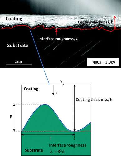
This work is the continuation of research within our group.[Citation28–31] The purpose of this investigation is to predict the adhesion failure and assess the reliability of coating–substrate system using the principles of debondment of the bi-layered cantilever induced by diffusion. For this purpose, two most important parameters that influence the adhesion in terms of debonding driving force are used for investigation.[Citation32–35] These parameters are interface roughness of coating–substrate and coating thickness as shown in Figure . The investigation has been performed using a ‘two set-up approach’: (i) set-up 1: constant coating thickness with variable interface roughness and (ii) set-up 2: constant interface roughness with variable coating thickness. At first, the experimental study is performed and the samples for the two set-ups are prepared accordingly. These experiments are performed using the samples prepared for two set-ups. The experiments involve Vickers indentation test and ASTM-B117 test. These experiments are performed to understand the behaviour of debonding driving force with the variation in interface roughness and coating thickness under two set-ups, respectively. Comparison of the values of debonding driving force for various values of interface roughness and coating thickness are used to find the critical/threshold in terms of debonding driving force. This critical/threshold defines the point of failure.
Figure 1. Cross sectional SEM of undulating nature of coating–substrate interface (roughness) and coating thickness in a spray coating system (above) and schematic of coating–substrate interface roughness and coating thickness (below).
After understanding the complete behaviour of debonding driving force using experimentation, a mathematical model for failure prediction is developed. Two independent mathematical models are developed for diffusion and bi-layer cantilever beam under material science and solid mechanics disciplines, respectively. These two models are then integrated to develop an equation for debonding driving force under mesomechanics. This equation is further modified to find the critical/threshold value of debonding driving force which defines the failure point of coating–substrate adhesion. An algorithm is developed based on finite difference method in order to simulate the timely variation of debonding driving force due to change in interface roughness and coating thickness. Further, critical/threshold points are defined on these simulated graphs which characterise three conditions of coating–substrate performance i.e. safe, critical and fail. At the end, a model for the assessment of reliability of coating–substrate system is developed by utilising the above developed failure prediction model.
2. Experimental set-up and observations
AISI 1010 Carbon Steel is used as a substrate and primer (red-oxide) is used as a coating in this paper. The primer is sprayed using conventional spraying gun. The experimental design has been divided into the following two set-ups to analyse the effect of interface roughness λ and coating thickness h on debonding divining force F,
| (i) | Set-up 1: constant coating thickness h with variable interface roughness λ. | ||||
| (ii) | Set-up 2: constant interface roughness λ with variable coating thickness h. | ||||
2.1. Samples preparation for set-up 1-with variable interface roughness λ
Set-up 1 is designed to analyse the effect of various values of interface roughness λ on debonding driving force F while keeping the coating thickness h constant for all the samples. Ten samples were prepared with interface roughness (μm): λ I = 0.4, λ II = 1.1, λ III = 2.4, λ IV = 4.1, λ V = 5.3, λ VI = 6.8, λ VII = 7.5, λ VIII = 8.6, λ IX = 9.4 and λ X = 10.6, respectively. All the samples had a constant coating thickness h = 30 μm. The values of interface roughness λ are measured using three-dimensional scanning interferometry.[Citation36] These roughness values are averaged through 10 data points per sample.
2.2. Samples preparation for set-up 2-with variable coating thickness h
Set-up 2 is designed to analyse the effect of various values of coating thickness h on the debonding driving force F while keeping the interface roughness λ constant for all samples. Ten samples were prepared with coating thicknesses (μm): h I = 10.8, h II = 14.6, h III = 18.5, h IV = 22.4, h V = 26.2, h VI = 30.1, h VII = 34, h VIII = 37.8, h IX = 41.7 and h X = 45.6, respectively. All the samples had a constant interface roughness λ = 5.3 μm. Like roughness, the values of coating thickness h are measured using three-dimensional scanning interferometry. These thickness values for the coatings are averaged through 10 data points per sample.
One important thing that was highly considered during sample preparation was that material properties of coating such as diffusivity and Young’s modulus should be constant for all the samples. Increase in diffusivity makes coating more permeable to diffusing component and decrease in Young’s modulus increases the flexibility of coating. Both the changes can significantly affect the results of debonding driving force. Diffusivity and Young’s modulus of coating depends on material’s microstructure.[Citation37,38]
2.3. Experimental observations
2.3.1. Vickers indentation test of samples
Debonding driving force F for the samples under each set-up (1 and 2) was calculated by deploying an artificial method of debonding i.e. Vickers indentation. Debonding driving force F of samples was calculated before the samples were subjected to ASTM-B117 environmental test.
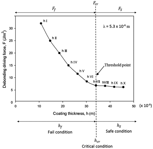
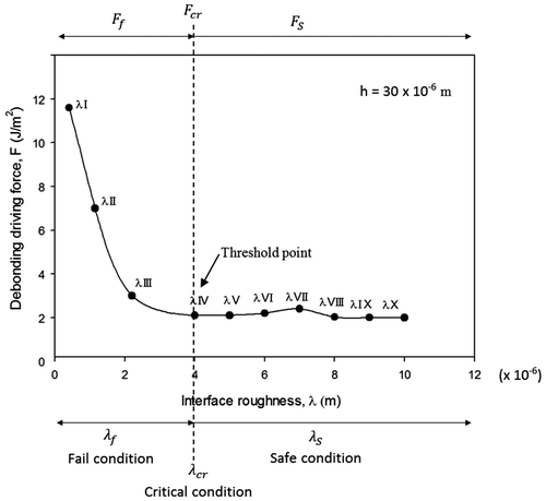
Debonding driving force F of samples for set-up 1 is shown in Figure (a). The graph indicates that the debonding driving force F decreases with an increase in interface roughness and becomes stable. The critical value of debonding driving force i.e. Fcr corresponding to critical interface roughness λcr indicates the threshold point on graph. This threshold is the incipient requirement for the debondment initiation. If the value of F corresponding to λ exceeds this threshold point, then this results in the debondment of coating from the substrate (fail condition). Conversely, if the value of F corresponding to λ is less than the threshold point, then the coating remains intact with the substrate (safe condition). Sample with interface roughness (μm) λ IV = 4.1 is treated as critical. Samples with interface roughness (μm) λ I = 0.4, λ II = 1.1, λ III = 2.4 are treated as fail. Samples with interface roughness (μm) λ V = 5.3, λ VI = 6.8, λ VII = 7.5, λ VIII = 8.6, λ IX = 9.4 and λ X = 10.6 are treated as safe.
Figure 2(a). Experimental observation using set-up 1: Debonding driving force as a function of interafce roughness λ keeping constant value of coating thickness h. Graph in figure also defines safe, critical and fail conditions for coating performance.
Debonding driving force F of samples for set-up 2 is shown in Figure (b). The graph indicates an exponential decay of debonding driving force F with an increase in coating thickness h. The critical value of debonding driving force i.e. Fcr corresponding to critical coating thickness hcr indicates the threshold point on graph. For set-up 2, sample with coating thickness (μm) h VII = 34 is treated as critical. Samples with coating thicknesses (μm) h I = 10.8, h II = 14.6, h III = 18.5, h IV = 22.4, h V = 26.2, h VI = 30.1 are treated as fail. Samples with coating thicknesses (μm) h VIII = 37.8, h IX = 41.7 and h X = 45.6 are treated as safe.
2.3.2. ASTM-B117 test of samples
ASTM-B117 environmental test was employed to analyse the debondment of coating under simulated environmental condition. This test was performed to investigate the performance of coating under the effect of saline fog at temperature T = 35 °C. This test makes use of sodium chloride which acts as a diffusing substance through coating. The same samples which were analysed using indentation were now subjected to environmental test. This exposure of samples to ASTM-B117 test gave rise to blisters on coating due to diffusing substance which results in coating debondment. The evaluation of these blisters was performed by using interferometry. The interferometry was used for three-dimensional mapping and volume measurement of blisters (within circled area) as shown in Table . Along with interferometry, ASTM-D714 was also used to evaluate the degree of blistering using photographic references of samples. Post ASTM-B117 test results showed that the samples with maximum interface roughness and coating thickness exhibit maximum resistance to coating failure and vice versa. Three samples from each set-up (1 and 2) under safe, critical and fail conditions are shown in Table with three colours (green-safe, yellow-critical and red-fail).
Table 1. Three samples from each set-up (1 and 2) under safe, critical and fail conditions. The interferometry was used for 3-D mapping and volume measurement of blisters (within circled area). ASTM-D714 was also used to evaluate the degree of blistering using photographic references of samples.
Next sections explain the development of a mathematical model based on the observations made from experimentation.
3. Modelling methodology
The debondment of coating from the substrate is a multidisciplinary problem. It needs to be investigated from multi-dimensions by fostering a close collaboration between material science and solid mechanics disciplines. Mesomechanics seeks to imply the principles of solid mechanics to microstructural constituent of materials such as coatings. This research takes the concepts of mesomechanics to the next level in order to predict the failure and analyse the service life of coatings bonded to the substrate. The developed model follows the methodology given in Figure .
Figure 3. Graphical depiction of the design for mathematical model for prediction of failure (modelling methodology).
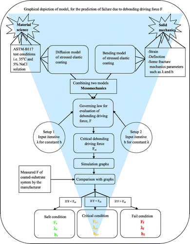
The design methodology follows the top-down approach. At the top of hierarchy, are the two major disciplines i.e. material science and solid mechanics. Each discipline encapsulates its constituent parameters, respectively. These parameters describe the mechanism of coating debondment. Temperature T (=35 °C) and percentage NaCl concentration (=5% NaCl solution) for ASTM-B117 test are described as constituent parameters forming material science. While strain, deflection of coating and some fracture mechanics parameters such as λ and h are described as constituent parameters forming solid mechanics. These respective constituent parameters of material science and solid mechanics are used for the development of diffusion model and bending model of stressed elastic coatings, respectively. The equations for both the approaches (diffusion and bending) are designed separately and then fused to form a governing law for the evaluation of debonding driving force F. The fusion of two distinct approaches (diffusion and bending) forms a basis of mesomechanics as shown in Figure . The debonding driving force F under mesomechanics is the key element responsible for the coating debondment.
Based on the numerical simulations with the finite difference method, the effect of interface roughness λ (set-up 1) and coating thickness h (set-up 2) on debonding driving force F is analysed. Critical/threshold points are calculated which are then defined on these simulation graphs. The simulation graphs along with critical/threshold points define the three conditions of coating performance based on the value of debonding driving force i.e. safe, critical and fail. The graphs which are generated using simulations can be used by the manufacturer at the time of manufacturing to design for durability by identifying that under which condition their manufactured coating–substrate system lies. These graphs can also be used to evaluate the performance of coatings in test conditions such as indentation test or ASTM-B117. Next section will focus on the design of mathematical model for failure prediction of coating–substrate system based on the above methodology.
4. Mathematical model (a failure prediction model)
4.1. Diffusion model of stressed elastic coating – application of material science concepts
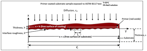
Thermodynamics and diffusion mechanism are the potential research topics in material science discipline. This part of modelling is specifically developed by considering the diffusion of substance k such as salt solution when the primer-coated steel sample is exposed to ASTM-B117 test condition i.e. T = 35 °C and 5% NaCl solution. The diffusing component n of a substance k maintains a concentration cn over an entire exposed surface of the coating as shown in Figure .
Figure 4. A schematic of coating–substrate system representation in terms of bi-layer cantilever beam.
The theory of irreversible thermodynamics states that the change in thermodynamics state of a system due to the loss or gain of a particle defines the chemical potential of the components.[Citation39] The chemical potential uk of substance k can be expressed as [Citation40]:(1)
where R is the molar gas constant; T is the temperature; is the chemical potential in the given standard state; an is the activity of component n which is equivalent to the concentration ck of a substance subject to the condition of infinitely dilute solutions.
When the thin elastic coating (primer) is subjected to a highly alkaline environment such as ASTM-B117 test, then the diffusion-induced stress tends to develop compound stress fields. For such case, the change in stress is coupled with the change in chemical potential and can be represented in the form of Maxwell relation as [Citation41]:(2)
where is the stress tensor; nk is the molar concentration of diffusing substance k;
represents the strain volume and shows the relationship between infinitesimal strain tensor
(ij = 1, 2, 3) and volume of element V;
is the volumetric strain tensor of diffusing substance k considering an isotropic strain volume,[Citation42] that is,
(3)
where is the Kronecker delta;
is the scalar term and can be treated as being equivalent to the partial molar volume
of diffusing substance k i.e.
=
.
can be found using Euler’s first theorem for homogeneous functions [Citation43] as,
(4)
where depends on the molar volume of solution
, where
denotes a generic extensive property of a solution which depends on temperature T, pressure P and molar concentration of diffusing substance k i.e. nk.
Consider one mole change in concentration nk from to
keeping temperature T and pressure P constant. For such a case,
is the change in molar volume associated with per molar change in concentration of a diffusing substance k from
to
. The molar volumes at two different stages of change are calculated using a well-known mass density relation as:
(5)
where ,
and
,
denote the molar masses and mass densities, respectively, at two different stages of change.
For the case of an isotropic solution, Equation (Equation2(2) ) can be integrated in conjunction with Equations (Equation3
(3) )–(Equation5
(5) ),
(6)
Substituting uk from Equation (Equation1(1) ) into Equation (Equation6
(6) ) gives,
(7)
where represents the chemical potential corresponding to the stressed state of the coating;
is the average of the three principle stresses of the stress tensor and
are the principle stresses.
The deformation of linear elastic ‘porous’ coating due to the coupling between the linear diffusion of a substance k and the stress tensors is defined by linear poroelasticity theory.[Citation44,45] This theory states that the infinitely slower atomic diffusion of a substance k compared to the deformation of stressed elastic coating will equilibrate the mechanical properties of coating much faster than that of diffusion. The concepts of linear poroelasticity can be used in conjunction with the formal theory of linear elasticity to model the current problem. Therefore, the principle stresses can be written as a sum of diffusion induced stresses
and residual stresses
i.e.
.
It is possible to minimise the effect of residual stress using specified temperature gradients and controlled phase transformations,[Citation46–50] therefore,
. Accordingly,
can be modified in terms of diffusion induced stress as:
(8)
Substituting Equation (Equation8(8) ) in Equation (Equation7
(7) ) gives the chemical potential
of a diffusing substance k in the stressed coating which is dependent on a scalar (
and a tensor (
) as:
(9)
where is a scalar term and does not include the effect of stress tensor.
Consider the case of an inhomogeneous distribution of solute particles in a non-ideal solution. The driving force for the diffusion of substance k is the gradient of chemical potential of that substance. Fick’s first law of diffusion relates the diffusion flux
of a substance k with the gradient of chemical potential as:
(10)
The vector form of diffusion flux is directly proportional to the gradient of chemical potential [Citation51];
is the diffusion coefficient of substance k in the stress-free isotropic coating.
Substituting Equation (Equation9(9) ) in Equation (Equation10
(10) ) gives the diffusion flux
of diffusing substance k in the stressed coating as:
(11)
The concentration of a substance k within the stressed coating changes with time. Fick’s second law of diffusion in conjunction with the law of conservation of mass can be applied as:(12)
Multiplying both sides of Equation (Equation11(11) ) with the gradient operator
and then substituting Equation (Equation11
(11) ) in Equation (Equation12
(12) ). This gives the differential equation which includes the effect of diffusion induced stress as:
(13)
Equation (Equation13(13) ) follows the law of conservation of mass, as the change of concentration of diffusing substance k with time
on the left side of Equation (Equation13
(13) ) must be equal to the local decrease of the diffusion flux and other two stress-assisted terms on right side of equation.
4.2. Bending model of bi-layered cantilever – application of solid mechanics concepts
This part of modelling is specifically designed based on the concepts of solid mechanics incorporating the principles of bi-layer cantilever beam. According to the current design, one adherend of the bi-layer cantilever beam acts as coating, while the other adherend acts as substrate. The interface between the coating and substrate is located at x = 0 along the coordinate axis; the free surface of the coating and the substrate is located at x = h and x = −s, respectively, as shown in Figure . It is worth nothing that for the case which is reported in this research is based on the fact that only one layer of cantilever which is the coating, exhibits bending. The reason is that the thickness of coating is much less than the thickness of substrate.
The analysis in this paper is based on the following assumptions: (i) coating thickness h is very small compared to substrate thickness s, (ii) coating thickness h is strictly small compared to its length lc i.e. (h/lc) < 1 as shown in Figure , (iii) coating and substrate materials are homogeneous, isotropic, linearly elastic and other parameters such as Young’s modulus, diffusivity and chemical potential are invariable during debonding and diffusion and (iv) the strain tensor along with principle strains is extremely small.
The analyses of the bending of bi-layer cantilever beam follow the assumption that the diffusion-induced stress is initially zero at time t = 0. After the incubation of diffusive substance k in both layers of cantilever beam at time t > 0, the layer which represents the coating, will start to bend and the diffusion-induced stress will therefore, appear.
According to Hsueh [Citation50], the strain distribution in a system (diffusion induced strain) ε can be decomposed into a uniform component εu and a bending component εb as:(14)
x = tb represents the neutral point of the bending axis in a coordinate system where bending strain component is zero; ζ represents the radius of curvature corresponding to diffusion. The analyses of strain distribution (Equation (Equation14
(14) )) at the interface of coating and substrate comply with the strain continuity equation in Timoshenko shear model.[Citation52]
The normal stresses in cantilever are related to thermal strain using stress–strain relation as [Citation50]:(15)
where dictates the thermal strain with
representing the thermal expansion coefficient and
representing the change in temperature. For diffusion processes, the coating properties may be assumed to change linearly [Citation53] with the concentration of diffusing substance k, which results in diffusion-induced stresses. Therefore, it is possible to calculate diffusion-induced stress by analogy to thermal stress. Prussin [Citation54] and Zhang et al. [Citation55], previously treated concentration gradients
analogously to those generated by temperature gradients
and partial molar volume
analogous to thermal expansion
. Therefore, Equation (Equation15
(15) ) can be modified to obtain the expressions for normal stresses in coating and substrate as:
(16a)
(16b)
is treated as the concentration change of the diffusing substance k from the original (stress-free) value where i = c, s. For the condition when the system has planar geometry rather than a linear geometry, then the bi-axial strains are identical along y and z plane, therefore, Ei can be replaced by Ei/(1 – vi), where vi is the Poison’s ratio.
Consider the ‘average stress distribution’ through both the layers of cantilever. The average diffusion-induced stress through coating and substrate can be defined by incorporating Equations (Equation16a(16a) ) and (Equation16b
(16b) ) as:
(17a)
(17b)
where = bh,
= bs and b = bs = bh. The strain and stress distribution in bi-layer cantilever beam (Equations (Equation14
(14) ), (Equation17a
(17a) ) and (Equation17b
(17b) )) are dependent on the solution of two parameters i.e.
and
. It is possible to find
and ζ by using the following two boundary conditions.
At first, the resultant force due to uniform stress component is zero, such that(18)
is determined by the solution of Equation (Equation18
(18) ),
(19)
where and
.
Second, the bending moment of cantilever layers with respect to neutral point of bending axis i.e. x = tb is zero, such that(20)
The bending curvature of cantilever 1/ζ can be determined from the solution of Equations (Equation14(14) ), (Equation17a
(17a) ), (Equation17b
(17b) ), (Equation19
(19) ) and (Equation20
(20) ) as,
(21)
where M is the applied moment such that =
and
=
When the concentration of diffusing substance k is distributed in a uniform pattern along both the layers of cantilever than, Equation (Equation21(21) ) can be modified as:
(22)
When the first-order approximation is taken, Equation (Equation22(22) ) becomes,
(23)
The above equations (Equation22(22) and Equation23
(23) ) which are derived for the bending of bi-layer cantilever due to diffusion of substance k are analogous to equations derived by Hsueh [Citation50] for thermal stresses when term
is replaced by (
. The equations are also analogous to equations derived by Xuan et al. [Citation56] for deformation of thin sensor films.
4.3. Combined model (diffusion and bending models) – mesomechanics approach
This part of modelling gives a holistic design based on diffusion and bending models. The stitching of both the components together and incorporating fracture mechanics concepts form the mesomechanics approach. This approach is further utilised to predict the coating failure. The modelling of this part follows the following assumptions: (i) average interface roughness Ra is less than the average wavelength of the roughness La at the interface i.e. (λ = Ra2/La) < 1 as shown in Figure , (ii) the frictional sliding plays a negligible role, (iii) the steady-state energy release rate G of the crack when its length r is far greater than coating thickness h is given by G = Gcr; where Gcr is the critical energy release rate.
Substituting the diffusion-induced stresses, which has been derived in Equation (Equation16a(16a) ) and (Equation16b
(16b) ) into Equation (Equation13
(13) ). This forms a coupling relationship between bending of cantilever layers and concentration of diffusing substance k.
(24a)
(24b)
In equations, ; where i = c, s. In the third part on right-hand side of Equation (Equation24a
(24a) ) and (Equation24b
(24b) ), the terms
can be written as:
and
.
The current research focuses on the deformation of coatings due to diffusing substance k. Therefore, Equation (Equation24a(24a) ) can be modified to calculate the change in diffusion-induced stress with time
due to the change in concentration of diffusing substance k with time
, such that,
(25)
The diffusion-induced stress, which is derived in Equation (Equation25(25) ), can be employed to calculate the effect of stresses near crack tips. These crack tips can reside near the regions of defects in coatings which can incubate the process of debonding. The conventional form of debonding index, as defined by Hutchinson [Citation57–59] is,
(26)
where r is the length of debonding region on the interface between coating and substrate; is the critical stress when the coating just begins to debond from the substrate in both plane strain and an axis symmetric mode.
Substituting Equation (Equation25(25) ) into Equation (Equation26
(26) ) gives the modified equation, such that,
(27)
For the coating debondment to initiate, the value of must exceed a critical value
. For the plane strain debonding problem,
= 1.
Griffith and Irwin’s employed an energy balance approach [Citation60,61] which was redefined by Hutchinson et al. [Citation58] to investigate failure mechanism due to debondment propagation at the interface. Debondment propagation at the interface is one of the main mechanisms for the failure of coating–substrate system. It is well known that strain energy release rate G is a measure of the driving force for debondment propagation. When G attains its critical value Gcr, the debondment propagates. In case of debonding in a homogeneous solid body, Gcr is a material constant, while for interface crack it is dependent on some interface parameters such as phase angle ψ. By incorporating Equation (Equation27(27) ), Hutchinson’s equation for elastic energy release rate G can be modified to redefine the debondment propagation problem in terms of concentration of diffusing substance k, such that,
(28)
where is the change in strain energy release rate with time which depends on the change in diffusion-induced stress with time,
.
=
is the applied moment of coating having thickness h;
=
is the constant which depends upon Poisson’s ratio of the coating.
in Equation (Equation28
(28) ) can be associated with mode-mix function
and
when condition
is met. Where
is the mode I toughness.[Citation58] Associating
with
makes the strain energy release rate
mode dependent, such that,
(29)
Mode-dependent strain energy release rate due to debonding can be adjusted using a dimensionless mode-mix function
. Debondment propagation depends on mode-adjusted debonding driving force F,[Citation62] such that,
(30)
The incipient requirement for debondment to propagate follows the condition . Upon substituting
in Equation (Equation29
(29) ), the incipient requirement becomes
. The value for incipient propagation of debondment is the critical value of
i.e. Gcr. The value of ‘intrinsic-toughness’
is always equal to
at the tip i.e.
.[Citation62]
is found by utilising Equation (Equation29
(29) ) specific to the condition
as,
(31)
where means that
exhibit an extremely small value, approaching to zero but is not exactly zero. Similarly,
means that the value of j approaches to 1 but is not exactly 1.
The mode-mix function is given as:
(32a)
(32b)
where in Equation (Equation32a
(32a) ) represents the interface roughness; parameter ω in Equation (Equation32b
(32b) ) is dependent upon Dundur’s elastic mismatch parameter χ.[Citation59] where
.[Citation63] The ‘intrinsic toughness’
which is found in Equation (Equation31
(31) ) is utilised in the term
in Equation (Equation32a
(32a) ).
The mode adjustment term (phase angle), in Equation (Equation32b
(32b) ) defines the mode (mode I or mode II) of debondment propagation. Interface is tougher in mode I compared to mode II. The mode adjustment term
is adjustable by using deflection index parameter
where
depends on
and is given as [Citation62]:
(33)
where is the constant which depends upon the value of Poison’s ratio.
The partial differential equation (PDE) for debonding driving force F can be determined from the solution of Equation (Equation28(28) ), (Equation30
(30) ), (Equation32a
(32a) ) and (Equation32b
(32b) ) as:
(34)
where ;
=
and B =
as
(Ra = Average roughness amplitude; La = Average roughness wavelength).
It is worth noting that equation depends on the concentration of diffusing substance which if becomes zero makes
= 0. It is clear that the above equation agrees with Hutchinson et al. [Citation58] for the same crack propagation problem when
(h) is replaced with
and
is replaced with
.
in Equation (Equation34
(34) ) is a function of two parameters i.e. interface roughness λ and coating thickness h. It is important to note that interface roughness λ only effects the magnitude of debonding driving force F with no influence on time discretisation, while coating thickness h effects the time discretisation of debonding driving force F. The ‘variation in magnitude’ of debonding driving force F is performed by utilising mode-mix function j(λ). Where j(λ) is a function of only one parameter i.e. interface roughness λ. Where j(λ) adjusts the mode of debondment propagation (mode I or mode II). However, ‘time dependent’ variation of debonding driving force F is performed by varying
(h) which effects
. Where
(h) is a function of only one parameter i.e. coating thickness h.
Equation (Equation34(34) ) can be utilised to find the critical values of debonding driving force Fcr, interface roughness λcr and coating thickness hcr for the two set-ups of experiment as follows.
Set-up 1: Constant h with variable λ – finding critical/threshold value
is found against the condition when
approaches to
(h) i.e.
(h) in Equation (Equation34
(34) ). This is only possible when j(λ) → 1.
is calculated using Equation (Equation28
(28) ). Therefore, for condition
, the value of-adjusted magnitude of
by adjusting j(λ) → 1 (in
always approaches to
(h). This is actually the critical value of debonding driving force which is a function of
and is represented as
= [
(h]. The generalised equation for finding
is given in Equation (Equation35a
(35a) ) which is derived from Equation (Equation34
(34) ).
If variation of becomes greater then
, than j(λ) starts to increase and magnitude of
(λ) starts to decrease which becomes much smaller compared to
(h) therefore, making interface more and more tougher.
(35a)
If variation in becomes less than
, then j(λ) starts to decrease and magnitude of
(λ) starts to increase resulting in coating debondment.
Set-up 2: Constant λ with variable h – finding critical/threshold value
is found against the condition when
(h) = 1, which upon substitution in Equation (Equation34
(34) ) gives Equation (Equation35b
(35b) ). The expression on right-hand side of Equation (Equation35b
(35b) ) returns the critical value of F. This critical value of debonding driving force is a function of hcr and is represented as
. Variation in h effects the variation of F with respect to time.
If variation of h becomes less than hcr, then (h) starts to increase, causing time-dependent debonding driving force F(h) to increase which results in the coating debondment.
(35b)
The reasons that why thicker coatings (h hcr) possess lower debonding driving force F are as follows: (i)
(h) is a direct function of bending curvature of coating
which inversely relates with the thickness of coating h as clear from Equation (Equation23
(23) ) and (ii) critical stress of the coating
increases with an increase in h which again reduces
(h) and ultimately results in lower
(h).
5. Mathematical model solution and implementation
The initial and boundary conditions for the stressed cantilever are expressed as follows:(36)
(37)
For numerical simulation work, all the parameters and variables, which are used in the equations, should be converted into dimensionless forms as:(38a)
(38b)
(38c)
(38d)
(38e)
(38f)
(38g)
(38h)
(38i)
(38j)
(38k)
(38l)
where ;
;
and it is assumed that
.
In this research, the newly developed algorithm follows a ‘two set-up approach’. The two set-ups can be generalised by utilising a PDE in Equation (Equation38j(38j) ) as:
(39a)
(39b)
Set-up 1 consists of a simple iterative method to update the value of interface roughness which is represented by variable
in Equation (Equation39a
(39a) ). This set-up is highlighted as an olive green box in Figure . The iteration of
is used only to adjust the ‘magnitude’ of debonding driving force
but has no influence on the time discretisation of
. The only parameter which influences the ‘time discretisation’ of
is the coating thickness h which is generalised in Equation (Equation39b
(39b) ) under set-up 2. The iterations of h are represented by n and the time states are represented by superscript
. Newton–Rhapson method [Citation64] is utilised to solve the time-varying PDE
. The governing PDE
for normalised debonding driving force
in the domain is discretised in time and space and cast into the matrix form using Newton–Rhapson method. This set-up is highlighted as grey box in Figure .
Figure 5. Algorithm for a two set-up approach used for estimating the debonding driving force as a function of interface roughness (using set-up 1) and coating thickness (using set-up 2).
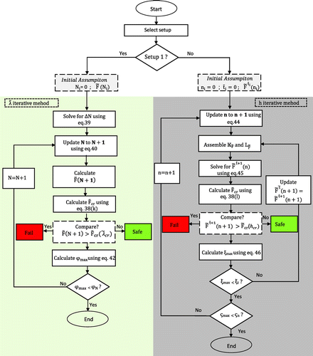
The two set-up algorithm follows the following steps.
| (i) | The algorithm starts with the selection of set-up. Set-up 1 is used to analyse the effect of | ||||
| (ii) | If set-up 1 is selected than the algorithm enters into set-up 1( | ||||
| (iii) | Next, the algorithm initialises the iterative process for a parameter
| ||||
| (iv) | This initially computed
| ||||
| (v) | For an updated | ||||
| (vi) | The interface roughness convergence criterion for variable
where | ||||
| (vii) | If set-up 2 is selected than the algorithm enters into set-up 2 (h iteration). The algorithm initialises the iterative process for a parameter
| ||||
| (viii) | This initially computed
| ||||
| (ix) | The initial time value ( | ||||
| (x) | The governing equation and boundary conditions for
where | ||||
| (xi) | For an updated | ||||
| (xii) | The time convergence criterion is calculated as:
where | ||||
| (xiii) | The thickness convergence criterion for variable n is calculated as: | ||||
(47)
where is a generic term representing
. For the condition
>
, the value of h is updated, and control returned to step (viii). For the condition
<
, the algorithm for set-up 2 ends.
6. Simulation results and discussion
6.1. Simulation results of set-up 1
For the case of relative coating thickness h/s being fixed, the effects of normalised interface roughness, , on normalised debonding driving force
are analysed using set-up 1 algorithm. These results are shown in Figure , where
= 0.5,
= 1,
= 5,
=10, 1/η = h/s = 0.1 and T/To= constant, where To is absolute temperature. From Figure , it is clear that the debonding driving force
decreases with an increase in interface roughness
and becomes stable after certain value of
. The debonding driving force
as a function of interface roughness
is time independent. Similar curves of
corresponding to time steps
= 0.05 to 0.25 are observed which are shown in Figure .
Figure 6. Simulation graph using set-up 1: Debonding driving force as a function of normalised interafce roughness
keeping constant value of relative coating thickness h/s. Simuation graph showing time independent behaviour of
for various values of time
. Simulation graph also defines safe, critical and fail conditions for coating performance.
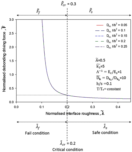
Figure shows the coating fail, critical and safe conditions in terms of debonding driving force and interface roughness
. When the interface roughness
is greater than critical
and the corresponding debonding driving force
is less than critical
, then the coating is considered to be safe and are represented as:
,
. Conversely, if
is less than critical
and corresponding
is greater than critical
, then the coating is considered to be fail and are represented as:
,
. Where,
= 0.2 and
= 0.3 are said be to be critical points for coating failure. This indicates that increasing the interface roughness is better in order to avoid coating debondment from substrate. However, this is subject to condition that the coating and substrate properties like thickness, Young’s modulus and diffusivity should remain constant with an increase in interface roughness.
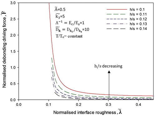
Figure shows the evolution of debonding driving force corresponding to various values of relative coating thickness h/s and normalised interface roughness
. Where
= 0.5,
= 1,
= 5,
= 10 and T/To = constant. Separate numerical simulation was conducted for this purpose apart from the set-up 1 algorithm in Figure . It is worth noting that the effect of normalised coating thickness h/s on debonding driving force
is dominant at lower interface roughness, when interface roughness
is less than 0.2. However, the debonding driving force
becomes stable and becomes independent of the value of normalised coating thickness h/s at higher interface roughness
, greater than 0.2. This means that at higher interface roughness, the coating substrate system becomes independent of the value of coating thickness. This is the reason that for some coating–substrate systems, the debonding driving force is independent of the coating thickness. It can also be concluded from Figure that at lower interface roughness
< 0.2, where it is expected that debonding driving force will be high, the debonding driving force can be minimised by increasing the coating thickness. However, this is subject to condition that Young’s modulus and diffusivity of coating should not change with an increase in interface roughness and coating thickness.
6.2. Simulation results of set-up 2
For the case of interface roughness and substrate thickness s being fixed, the effects of relative coating thickness, h/s, on normalised debonding driving force
are analysed using set-up 2 algorithm. These results are shown in Figure , where
= 0.5,
= 1,
= 5,
= 10,
0.5 and T/To = constant, where To is absolute temperature. It is assumed that the diffusivity
of the coating is 10 times more compared to the diffusivity
of the substrate and therefore, leads to
. From Figure , it is observed that the debonding driving force
decreases with increasing the relative coating thickness, h/s. The relative coating thickness increases with an increase in h because s is constant and is assumed to be large. This indicates that increasing the thickness of coating h is better in order to avoid coating debondment from substrate. However, this is subject to condition that the diffusivity
should not increase and Young’s modulus
should not decrease with an increase in the thickness h. If diffusivity
of the coating increases with an increase in thickness h, then this means that coating is becoming more permeable to diffusing component and therefore, leads to coating failure. If Young’s modulus
of the coating decreases with an increase in thickness h than this means that the flexibility of coating is increasing which results in higher debonding driving force and in turn results in coating failure.
Figure 8. Simulation graph using set-up 2: Normalised debonding driving force as a function of relative coating thickness h/s keeping constant value of normalised interafce roughness
. Simuation graph showing time discritisation of
for various values of h/s. Simulation graph also defines safe, critical and fail conditions for coating performance.
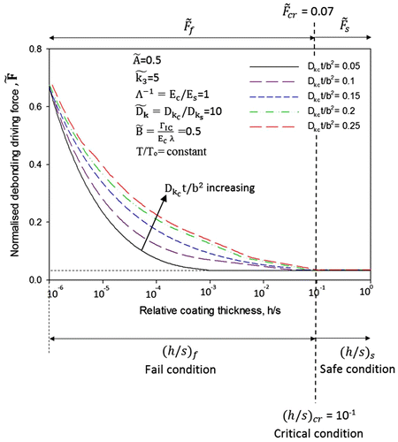
Comparatively, for a less relative coating thickness, i.e. h/s < 10−1, debonding driving force will increase with increasing the time at a given h/s. However, a time-independent debonding driving force
is observed when the thickness h of coating is either very small (h/s < 10−6) or comparable (h/s > 10−1) to the thickness s of the substrate. Figure indicates the coating fail, critical and safe conditions in terms of debonding driving force
and relative coating thickness h/s. When the relative coating thickness h/s is greater than 10−1 and the corresponding debonding driving force
is less than 0.07, then the coating is considered to be safe and is represented as:
,
. Conversely, if h/s is less than 10−1 and corresponding
is greater than 0.07, then the coating is considered to be fail and are represented as:
,
. Where
= 10−1 and
= 0.07 are said be to be critical points for coating failure.
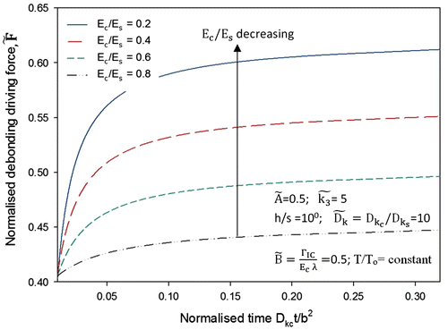
It is important to analyse the effects of diffusivity ratio on debonding driving force
, therefore, a separate numerical simulation was conducted for this purpose apart from the set-up 2 algorithm in Figure . For a given diffusivity of substrate
, the effects of the diffusivity ratio,
, on the debonding driving force
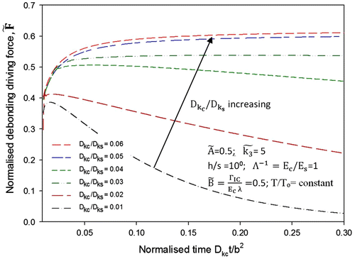
are shown in Figure , where
= 0.5,
= 5, h/s = 100 = 1,
= 1,
0.5 and T/To = constant. From Figure , it is evident that the trends for debonding driving force
are identical for various ratios of diffusivity corresponding to the very short diffusing time i.e.
= 0.02. After then, the debonding driving force
reaches a maximum and then decreases gradually with increasing the time, especially for the small ratio of diffusivity,
. However, the debonding driving force
remains constant for higher ratio of diffusivity. This indicates that in order to avoid high and stable debonding driving force
, the diffusivity of coating
should be kept small by the manufacturers guaranteeing least permeability to diffusing substance k.
Figure 9. Effects of diffusivity ratio of coating and substrate on normalised debonding driving force
.
Similar analysis, like that of , was also performed for
. Figure shows the evolvement of debonding driving force
corresponding to various Young’s modulus ratios,
where
= 0.5,
= 5, h/s = 100 = 1,
= 10,
0.5 and T/To = constant. As shown in Figure , the debonding driving force
increases sharply to a maximum and then becomes stable with an increase in time. It is worth noting that the debonding driving force
increases with decreasing the ratio of Young’s modulus,
. This indicates that for a given thickness h and concentration of diffusing substance, decreasing the flexibility of coating by increasing the Young’s modulus
can reduce the debonding driving force
. This increase in Young’s modulus
of coating will improve the adhesion of coating with substrate.
7. Reliability assessment model (application of failure prediction model)
Interface roughness and coating thickness are the two most important parameters that contribute towards the failure of coating–substrate system. Therefore, during the design process, the manufacturers must be aware of the reliability of coating–substrate system, which is being manufactured. The reliability assessment [Citation65] for coating–substrate system is performed using a probabilistic approach. The assessment is based on failure prediction model (in Section 4). The reliability assessment model can further be utilised in prognostics which is defined as the ability to predict accurately and precisely the remaining useful life of a failing component or system.[Citation66] In this research, the failing system is coating–substrate system.
7.1. Debondment initiation
The debonding driving force equal to its critical value is the incipient requirement for the initiation of coating debondment. The PDE (f(x)) for the debonding driving force (in Equation (Equation34(34) )) is a probability density function [Citation67,68] over the range of
to
. The limits
and
represent the initial and critical values, respectively, for variables λ and h. The cumulative density function
is,
(48)
where represents the value of debonding driving force at which the debondment initiates. This is actually the point of failure for coating–substrate system.
7.2. Instantaneous failure probability
The instantaneous failure probability P(X) of coating–substrate system is the ratio of probability of failure due to debonding driving force to the probability of use without failure , so
(49)
(50)
where is the commutative density function and is found using Equation (Equation48
(48) ).
8. Conclusions
A failure prediction and reliability assessment model for coating–substrate system has been developed based on a multidisciplinary approach. Coating–substrate adhesion depends on the debonding driving force. Higher debonding driving force accounts for low interface adhesion and vice versa. A mathematical equation for debonding driving force is developed incorporating the concepts of material science and solid mechanics. The equation is further modified to find the critical value of debonding driving force. This critical value defines the point of failure and is utilised to evaluate the performance of coating–substrate system i.e. safe, critical and fail. The model is also used to assess the reliability of coating–substrate system which can be used by the manufacturers during the design process. Interface roughness and coating thickness are two most important parameters which influence the performance of coating–substrate system. The debonding driving force decreases with an increase in the interface roughness and coating thickness. However, this is subject to condition that the material properties of coating such as, diffusivity should not increase and Young’s modulus
should not decrease with an increase in the interface roughness and coating thickness. For example, if diffusivity
of the coating increases with an increase in coating thickness, then this means that coating is becoming more permeable to diffusing component and therefore, leads to coating failure. Likewise, if Young’s modulus
of the coating decreases with an increase in coating thickness then this means that the susceptibility to failure of coating is increasing which results in higher debonding driving force and in turn results in coating failure. Therefore, for best performance of coating–substrate system, it is important to keep diffusivity low and Young’s modulus high while increasing interface roughness and coating thickness.
The model is developed based on the observation recorded from experimentation. The experiment involved the sample preparation according to the ‘two set-up approach’ i.e. (i) set-up 1: constant coating thickness with variable interface roughness and (ii) set-up 2: constant interface roughness with variable coating thickness. The experiments comprised of Vickers indentation test and ASTM-B117 test. These experiments were performed to understand the behaviour of debonding driving force with the variation in interface roughness and coating thickness under two set-ups, respectively.
Nomenclature
Unless otherwise specified, the following nomenclature is used in this paper.
| Notation | = | Description |
| = | chemical potential of substance k | |
| = | chemical potential in the given standard state | |
| R | = | molar gas constant |
| T | = | temperature |
| an | = | activity of component n |
| ck | = | concentration of substance k |
| = | stress tensor | |
| nk | = | molar concentration of substance k |
| = | strain volume | |
| = | infinitesimal strain tensor | |
| V | = | volume of element |
| = | volumetric strain tensor of diffusing substance k | |
| = | Kronecker delta | |
| = | scalar term equal to | |
| = | partial molar volume of substance k | |
| = | molar volume of solution | |
| P | = | pressure |
| = | mass density | |
| = | molar mass | |
| = | chemical potential corresponding to the stressed state of the coating | |
| = | average of principle stresses of the stress tensor | |
| = | principle stresses | |
| = | diffusion induced stresses | |
| = | residual stresses | |
| = | diffusion flux of a substance k | |
| = | diffusion coefficient of substance k | |
| h | = | thickness of coating |
| s | = | thickness of substrate |
| x | = | free surface |
| lc | = | length of coating |
| = | diffusion induced strain | |
| = | uniform component | |
| = | bending component | |
| ζ | = | radius of curvature of coating corresponding diffusion |
| = | thermal expansion coefficient | |
| M | = | applied moment |
| Ra | = | average interface roughness |
| La | = | average wavelength of the roughness |
| λ | = | interface roughness (= |
| G | = | energy release rate |
| Gcr | = | critical energy release rate |
| = | change in diffusion induced stress with time (= | |
| = | critical stress when the coating just begins to debond | |
| = | debonding index (= | |
| = | critical debonding index | |
| j | = | mode-mix function |
| = | mode I toughness | |
| F | = | debonding driving force |
| χ | = | Dundur’s elastic mismatch |
| ω | = | angular deflection parameter dependent upon Dundur’s elastic mismatch |
| = | mode adjustment term | |
| = | deflection index parameter |
Acknowledgements
This research is joint funded by Defence Science and Technology Laboratory (DSTL), Ministry of Defence (MoD) and Bournemouth University UK. The authors acknowledge their support and contributions.
Additional information
Funding
References
- Koleske JV. Paint and coating testing manual: fifteenth edition of the Gardner-Sward handbook. Vol. 17. ASTM International; 1995. Available from: http://www.astm.org/DIGITAL_LIBRARY/MNL/SOURCE_PAGES/MNL17-2ND_foreword.pdf
- Balslev I. Influence of uniaxial stress on the indirect absorption edge in silicon and germanium. Phys. Rev. 1966;143:636–647.10.1103/PhysRev.143.636
- Begley MR, Utz M. Multiscale modeling of adsorbed molecules on freestanding microfabricated structures. J. Appl. Mech. 2008;75:021008.10.1115/1.2793130
- Mahmoodi SN, Afshari M, Jalili N. Nonlinear vibrations of piezoelectric microcantilevers for biologically-induced surface stress sensing. Commun. Nonlinear Sci. Numer. Simul. 2008;13:1964–1977.10.1016/j.cnsns.2007.03.030
- Tsui Y, Doyle C, Clyne T. Plasma sprayed hydroxyapatite coatings on titanium substrates. Part 1: mechanical properties and residual stress levels. Biomaterials. 1998;19:2015–2029.10.1016/S0142-9612(98)00103-3
- Hainsworth S, McGurk M, Page T. The effect of coating cracking on the indentation response of thin hard-coated systems. Surf. Coat. Technol. 1998;102:97–107.10.1016/S0257-8972(97)00683-X
- Clyne T, Gill S. Residual stresses in thermal spray coatings and their effect on interfacial adhesion: a review of recent work. J. Therm. Spray Technol. 1996;5:401–418.10.1007/BF02645271
- Clyne T. Residual stresses in surface coatings and their effects on interfacial debonding. Key Eng. Mater. 1995;116:307–330.
- Tsui Y, Clyne T. An analytical model for predicting residual stresses in progressively deposited coatings. Part 1: planar geometry. Thin Solid Films. 1997;306:23–33.10.1016/S0040-6090(97)00199-5
- Howard S, Tsui Y, Clyne T. The effect of residual stresses on the debonding of coatings – I. A model for delamination at a bimaterial interface. Acta Metall. Mater. 1994;42:2823–2836.10.1016/0956-7151(94)90223-2
- Podstrigach YS, Shevchuk P. Effect of surface layers on diffusion processes and the resulting stress state in solids. Soviet Mater. Sci. 1968;3:420–426.10.1007/BF00716058
- Ida Y. Thermodynamic theory of nonhydrostatically stressed solid involving finite strain. J. Geophys. Res. 1969;74:3208–3218.10.1029/JB074i012p03208
- Larché F, Cahn J. A linear theory of thermochemical equilibrium of solids under stress. Acta Metall. 1973;21:1051–1063.10.1016/0001-6160(73)90021-7
- Kamb WB. The thermodynamic theory of nonhydrostatically stressed solids. J. Geophys. Res. 1961;66:259–271.10.1029/JZ066i001p00259
- Larcht’e F, Cahn J. The effect of self-stress on diffusion in solids. Acta Metall. 1982;30:1835–1845.10.1016/0001-6160(82)90023-2
- Stephenson GB. Deformation during interdiffusion. Acta Metall. 1988;36:2663–2683.10.1016/0001-6160(88)90114-9
- Daruka I, Szabó I, Beke D, Cserháti C, Kodentsov A, Van Loo F. Diffusion-induced bending of thin sheet couples: theory and experiments in Ti–Zr system. Acta Mater. 1996;44:4981–4993.10.1016/S1359-6454(96)00099-7
- Nguyen T, Hubbard J, Pommersheim J. Unified model for the degradation of organic coatings on steel in a neutral electrolyte. J. Coat. Technol. 1996;68:45–56.
- Prawoto Y, Kamsah N, Mat Yajid M, Ahmad Z. Energy density mechanics applied to coating blistering problems. Theor. Appl. Fract. Mech. 2011;56:89–94.10.1016/j.tafmec.2011.10.004
- Prawoto Y, Onn IH. Application of J-integral concept on blister coating problem. Eng. Fract. Mech. 2012;92:114–125.10.1016/j.engfracmech.2012.05.013
- Cui Z, Gao F, Qu J. A finite deformation stress-dependent chemical potential and its applications to lithium ion batteries. J. Mech. Phys. Solids. 2012;60:1280–1295.10.1016/j.jmps.2012.03.008
- Yang F, Li J. Diffusion-induced beam bending in hydrogen sensors. J. Appl. Phys. 2003;93:9304–9309.10.1063/1.1569980
- Rusanov AI. Surface thermodynamics revisited. Surf. Sci. Rep. 2005;58:111–239.10.1016/j.surfrep.2005.08.002
- Wang W, Lee S, Chen J. Effect of chemical stress on diffusion in a hollow cylinder. J. Appl. Phys. 2002;91:9584–9590.10.1063/1.1477624
- Xuan F-Z, Cao L-Q, Wang Z, Tu S-T. Mass transport in laser surface nitriding involving the effect of high temperature gradient: simulation and experiment. Comput. Mater. Sci. 2010;49:104–111.10.1016/j.commatsci.2010.04.031
- Prawoto Y. Solid mechanics for materials engineers: principles and applications of mesomechanics. 2014. Available from: http://www.amazon.com/MECHANICS-MATERIALS-Principle
- Nazir MH, Khan ZA, Stokes KA. Unified mathematical modelling and simulation for cathodic blistering mechanism incorporating diffusion and fracture mechanics concepts. J. Adhes. Sci. Technol. Forthcoming 2015. doi:10.1080/01694243.2015.1022496.
- Nazir M, Khan Z, Stokes K. Modelling of metal-coating delamination incorporating variable environmental parameters. J. Adhes. Sci. Technol. 2014;1:29–32.
- Saeed A, Khan Z, Clark M, Nel M, Smith R. Non-destructive material characterisation and material loss evaluation in large historic military vehicles. Insight. 2011;53:382–386.10.1784/insi.2011.53.7.382
- Saeed A, Khan ZA, Hadfield M, Davies S. Material characterization and real-time wear evaluation of pistons and cylinder liners of the Tiger 131 military tank. Tribol. Trans. 2013;56:637–644.10.1080/10402004.2013.771416
- Saeed A, Khan ZA, Montgomery E. Corrosion damage analysis and material characterization of sherman and centaur – the historic military tanks. Mater. Perform. Char. 2013;2:1–16.
- Lu TQ, Zhang WX, Wang T. The surface effect on the strain energy release rate of buckling delamination in thin film–substrate systems. Int. J. Eng. Sci. 2011;49:967–975.10.1016/j.ijengsci.2011.05.009
- Sheeja D, Tay B, Leong K, Lee C. Effect of film thickness on the stress and adhesion of diamond-like carbon coatings. Diamond Relat. Mater. 2002;11:1643–1647.10.1016/S0925-9635(02)00109-7
- Leterrier Y, Andersons J, Pitton Y, Månson JA. Adhesion of silicon oxide layers on poly (ethylene terephthalate). II: effect of coating thickness on adhesive and cohesive strengths. J. Polym. Sci., Part B: Polym. Phys. 1997;35:1463–1472.10.1002/(ISSN)1099-0488
- Moody N, Venkataraman S, Nelson J, Worobey W, Gerberich W. Interface roughness effects on adhesion of Ta2N films. Mat. Res. Soc. Symp. Proc. 1993;327:337–342.10.1557/PROC-327-337
- Sarikaya O. Effect of some parameters on microstructure and hardness of alumina coatings prepared by the air plasma spraying process. Surf. Coat. Technol. 2005;190:388–393.10.1016/j.surfcoat.2004.02.007
- Yagmur L. Effect of microstructure on internal friction and Young’s modulus of aged Cu–Be alloy. Mater. Sci. Eng. A. 2009;523:65–69.10.1016/j.msea.2009.05.047
- Fauchais P, Vardelle A. Thermal sprayed coatings used against corrosion and corrosive wear. In: Jazi H, editor. Advanced plasma spray applications. France: InTech; 2012. 250p. ISBN: 978-953-51-0349-3.
- Moran MJ, Shapiro HN, Boettner DD, Bailey M. Fundamentals of engineering thermodynamics. New York, NY: Wiley; 2010.
- Lewis GN. Outlines of a new system of thermodynamic chemistry. In: Proceedings of the American Academy of Arts and Sciences. Boston (MA): Metcalf; 1907. p. 259–293.10.2307/20022322
- Li JC-M. Physical chemistry of some microstructural phenomena. Metall. Trans. A. 1978;9:1353–1380.
- Li JC. High-angle tilt boundary – a dislocation core model. J. Appl. Phys. 1961;32:525–541.10.1063/1.1736036
- Kellogg OD. Foundations of potential theory. New York (NY): Frederick Ungar; 1929.10.1007/978-3-642-90850-7
- Wang H. Theory of linear poroelasticity with applications to geomechanics and hydrogeology. Princeton (NJ): Princeton University Press; 2000.
- Wang HF. Theory of linear poroelasticity. Princeton series in geophysics. Princeton (NJ): Princeton University Press; 2000.
- Michaleris P, Dantzig J, Tortorelli D. Minimization of welding residual stress and distortion in large structures. Weld. J. (NY). 1999;78:361–366.
- Lados DA, Apelian D. Wang L. Minimization of residual stress in heat-treated Al–Si–Mg cast alloys using uphill quenching: mechanisms and effects on static and dynamic properties. Mater. Sci. Eng. A. 2010;527:3159–3165.10.1016/j.msea.2010.01.064
- Freund L, Floro J, Chason E. Extensions of the Stoney formula for substrate curvature to configurations with thin substrates or large deformations. Appl. Phys. Lett. 1999;74:1987–1989.10.1063/1.123722
- Klein CA. How accurate are Stoney’s equation and recent modifications. J. Appl. Phys. 2000;88:5487–5489.10.1063/1.1313776
- Hsueh C-H. Modeling of elastic deformation of multilayers due to residual stresses and external bending. J. Appl. Phys. 2002;91:9652–9656.10.1063/1.1478137
- Zhang H, Davison W. Performance characteristics of diffusion gradients in thin films for the in situ measurement of trace metals in aqueous solution. Anal. Chem. 1995;67:3391–3400.10.1021/ac00115a005
- Cowper G. The shear coefficient in Timoshenko’s beam theory. J. Appl. Phys. 1966;33:335–340.10.1115/1.3625046
- David W, Thackeray M, De Picciotto L, Goodenough J. Structure refinement of the spinel-related phases Li2Mn2O4 and Li0.2Mn2O4. J. Solid State Chem. 1987;67:316–323.10.1016/0022-4596(87)90369-0
- Prussin S. Generation and distribution of dislocations by solute diffusion. J. Appl. Phys. 1961;32:1876–1881.10.1063/1.1728256
- Zhang X, Shyy W, Marie Sastry A. Numerical simulation of intercalation-induced stress in Li-ion battery electrode particles. J. Electrochem. Soc. 2007;154:A910–A916.10.1149/1.2759840
- Xuan F-Z, Shao S-S, Wang Z, Tu S-T. Influence of residual stress on diffusion-induced bending in bilayered microcantilever sensors. Thin Solid Films. 2010;518:4345–4350.10.1016/j.tsf.2010.01.033
- Hutchinson J, He M, Evans A. The influence of imperfections on the nucleation and propagation of buckling driven delaminations. J. Mech. Phys. Solids. 2000;48:709–734.10.1016/S0022-5096(99)00050-2
- Hutchinson J, Thouless M, Liniger E. Growth and configurational stability of circular, buckling-driven film delaminations. Acta Metall. Mater. 1992;40:295–308.10.1016/0956-7151(92)90304-W
- Hutchinson JW. Mixed mode fracture mechanics of interfaces. Metal Ceram. Interfaces. 1990;4:295–306. 10.1016/B978-0-08-040505-6.50037-4
- Collins JA. Failure of materials in mechanical design: analysis, prediction, prevention. New York (NY): Wiley; 1993.
- Irwin GR. Fracturing of metals. Cleveland (OH): American Society of Metals; 1949. p. 147–166.
- Hutchinson JW. Stresses and failure modes in thin films and multilayers. Lecture notes. 1996. Available from: http://www.seas.harvard.edu/hutchinson/papers/462-5.pdf
- Schmauder S, Meyer M. Correlation between Dundurs’ parameters and elastic constants. Z. Metallkd. 1992;83:524–527.
- Sheen D. Introduction to numerical analysis. 1980. Available from: http://www.osti.gov/eprints/topicpages/documents/record/784/0034855.html
- Mitchell AR, Griffiths DF. The finite difference method in partial differential equations. NewYork (NY): Wiley; 1980.
- Brown D, Darr D, Morse J, Laskowski B. Real-time corrosion monitoring of aircraft structures with prognostic applications. In: Annual conference of the Prognostics and Health Management Society. Vol. 3. Minneapolis (MN): Prognostics and Health Management (PHM) Society; 2012. p. 1–12. Available from: http://www.phmsociety.org/sites/phmsociety.org/files/phm_submission/2012/phmc_12_018.pdf
- Hartzell AL, Da Silva MG, Shea HR. MEMS reliability. NewYork (NY): Springer; 2011.
- Parzen E. On estimation of a probability density function and mode. Ann. Math. Stat. 1962;33:1065–1076.10.1214/aoms/1177704472

