
 ?Mathematical formulae have been encoded as MathML and are displayed in this HTML version using MathJax in order to improve their display. Uncheck the box to turn MathJax off. This feature requires Javascript. Click on a formula to zoom.
Abstract
Composites have been used extensively in various engineering applications including automotive, aerospace, and building industries. Hybrid composites made from two or more different reinforcements show enhanced mechanical properties required for advanced engineering applications. Several issues in composites were resolved during the last few years through the development of new materials, new methods and models for hybrid joints. Many components in automobile are joined together either by permanent or temporary fastener such as rivets, welding joint and adhesively bonded joints. Increasing use of bonded structures is envisaged for reducing fastener count and riveted joints and there by drastically reducing assembly cost. Adhesive bonding has been applied successfully in many technologies. In this paper, scientific work on adhesively bonded composites and hybrid composites are reviewed and discussed. Several parameters such as surface treatment, joint configuration, material properties, geometric parameters, failure modes, etc. that affect the performance of adhesive bonded joints are discussed. Environmental factors like pre-bond moisture and temperature, method of adhesive application are also cited in detail. A specific case of adhesive joints in hybrid bonded-bolted joints is elaborated. As new applications are expanding in the field of composites joining and adhesive joints, it is imperative to use information on multiple adhesives and their behaviour in different environmental conditions to develop improved adhesive joint structure in mechanical applications.
Introduction
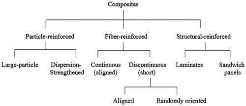
Composites are multiphase system obtained by combining two or more different materials that are mixed together to provide specific properties. The individual materials do not mix or merge together completely in the composite. However, they act together as a single entity. The properties of the composite material are superior to that of individual materials from which it is fabricated or formed. Many composite materials have at least one reinforcing member in the form of fibres, particles, flake, fabric, etc. which provide strength to the composite. Composites containing more than one type of reinforcement are commonly called “hybrid composites”. The term 'hybrid' is generally used to denote the incorporation of two or more different materials into one single system and the quantity of addition can either be on a small scale (Fibres, tows, etc.) or on a large scale (layers, pultrusions, ribs, etc.). Composites are also classified as particle reinforced, fibre reinforced and sandwich or laminated structure based on the geometry of the reinforcing materials as shown in [Citation1].
Figure 1. Tree diagram of the types of composites.
Reinforcements in composites
Based on the size and nature, the reinforcements are normally classified as particles (regular, irregular, etc.) continuous fibre, short fibre, non-woven, woven fabric, etc. as given in .
Figure 2. Types of reinforced composites.
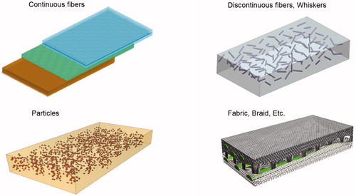
Particle-reinforced composites
Particulate reinforcements have the size in the range between microns to few centimeters having large regular or irregular shapes with comparatively fine or coarse particles. Composites filled with particulate reinforcement are designed to produce unusual combinations of properties rather than improving strength. They are distinguished based on strengthening mechanism i.e. dispersion-strengthened composites, large-particle composites, etc. Concrete is one such particulate composite having reinforcement effect from mixing of aggregates, sand and cement through chemical interaction upon setting.
Fibre-reinforced composites
Fibre-reinforced plastics (FRP), also called fibre-reinforced polymer, is a composite material having polymer as a matrix having fibre as a reinforcement. The fibres are usually glass fibre, carbon fibre, aramid fibre or natural fibres such as basalt, jute, sisal, flax, coir, etc. The polymer is typically thermoset resin such as epoxy, vinyl ester, unsaturated polyester or phenol formaldehyde. FRPs are commonly used in aerospace, automotive, marine, construction and structural engineering applications. Generally, composites reinforced with continuous fibre show high strength and stiffness. Discontinuous short fibres are used only when manufacturing economics dictate the use of a process method.
Structural composites
Structural composites are special class of composites and their characteristics are not only depend on properties of the constituent materials but also on the geometrical design of various structural elements. These composites are classified into two classes namely laminar composites and sandwich structures.
The materials of metal sheets, cotton, paper, and woven glass fibres etc, used in fabrication of laminar composites are embedded in a plastic matrix. Examples of laminar composites are thin coatings, thicker protective coatings, claddings, bimetallics and laminates. Many laminar composites are designed to increase corrosion resistance while retaining the advantages of low cost, high strength and lightweight.
Sandwich structures consist of thin layers of facing material joined to a lightweight core material sandwiched between facing as shown in . Neither the filler material nor the facing material is strong or rigid enough to provide strength but the composite possesses both properties [Citation2]. Example: Corrugated cardboard.
Figure 3. Sandwich structures.
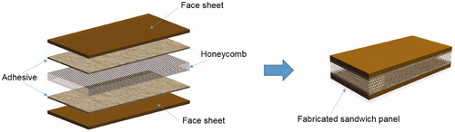
Typical face materials include aluminium alloys, fibre reinforced plastics, titanium, steel and plywood. Foamed polymers, synthetic rubbers, inorganic cement, balsa wood, etc. are used as core materials. Sandwich structures are used in many applications like roofing, flooring, building walls and in aircraft for a section of wings, fuselage and tailplane skins.
Defects in composite structure
In comparison to metals, structural composites are more prone to damage. Defects are usually introduced during manufacturing process mainly due to a wrong number of composite plies, improper curing temperature, poor resin choice, foreign-body inclusions or faulty processing conditions [Citation3,Citation4]. The commonly occurring defects and their causes are listed in .
The most common defects which are observed in the adhesive bonded joints are delamination and de-bonding. These defects are due to air entrapment, excessive catalyst, propagation of cracks through the matrix and lack of adhesive strength etc.
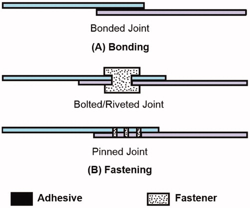
Joining methods in composites
Mechanical fasteners and adhesives or both are used to join composites. The joining technique used on a particular composite depends on the application and material characteristics. For instance, composites used in aircraft are usually joined by a combination of mechanical fasteners and adhesives on the other hand, composites used in automobiles are often joined only with adhesives. Mechanical fasteners such as rivets, pins, two-piece bolts, and blind fasteners made of titanium, stainless steel and aluminium are used for composite joints. The types of joining technique are illustrated in .
Figure 4. Types of joining techniques.
Adhesive bonding is so desirable when it is compared to riveting, welding, and many other mechanical fastening [Citation5] due to following advantages
Thin gauge materials may be used with an intention of weight reduction and cost savings. Additionally, simplified design can be used to reduce the number of production components.
Reduction or elimination of mechanical operations such as milling, machining, and forming operation.
Large bonding area can be prepared with a minimal binding force without special skills.
Improved aerodynamics, smoothness and visual appearance.
Sealing and corrosion resistant joints whilst joining incompatible adherends.
Improved electrical and thermal insulation.
Fatigue resistance to the magnitude of twenty times higher than that of riveted structures for identical elements.
Superior damping characteristics and noise reduction compared to riveted assemblies.
Tolerance to changes in coefficients of thermal expansion while joining distinct adherents.
Unlike metals, ceramics and wood, polymers and composites have some inherent physical characteristics which do not allow them to use in traditional joining techniques such as fastening, clinching, etc. as they generate critical stresses. Similarly, composite manufacturing method do not support for traditional joining methods. Furthermore, in FRP structures, drilling a bolt holes breaks the fibres in the composites, causing numerous failures like peeling of the higher plies at the access of the hollow, resin degradation at the wall of the hole and delamination of the remaining plies within the laminate [Citation6,Citation7]. These damages can initiate fatigue cracks and significantly reduce fatigue strength of mechanical joints [Citation8]. Moreover, in mechanical fastening, the fasteners themselves place a significant source of weight increment. In a heavy structure like ship and aircraft, the reduction of the quantity of fasteners count is considered as a weight reduction operation [Citation9]. The adhesive bonding can be considered as the best joining technique between similar (composite and composite) or dissimilar (composite and metal) structures which do not require subsequent disassembly for maintenance and inspection. FRP composites are superior to metals in terms of precise strength and stiffness, formability and corrosion resistance [Citation10].
For joining the composite structures, two principal strategies are used along with mechanical fastening and adhesive bonding. In mechanical fastening, the use of bolts or rivets is simple, and it is feasible to acquire high joint strength with small scatter and it is extensively used for metal structures. The drawbacks of mechanical joints are
Increases weight of the entire structure and
Overall low sealing performance.
Additionally, in mechanical joints, the stress concentration and tip crack formation near the drill holes are high and the cross-sectional area of structures is decreased because in the presence of bolt holes [Citation6,Citation11]. The Boeing 787 Dreamliner airplane is made up of more than 50% composite materials in its structure using adhesive joints. The technological improvements allowed the use of composites in large quantities and the consumption of fuel in 787 Dreamliner is 20% less than the other airplanes due to reduced weight without much change in its size.
Adhesively bonded joints
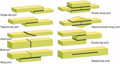
In adhesive bonding technique, the adhesive is applied on the surfaces to be joined and then combined [Citation12]. Literature study shows that numerous examples are available to support the suitable adhesive joints for all kinds of mechanical loads [Citation3]. Various types of joints such as a single lap joint, double lap joint, tapered lap joint, scarf joint, butt joint, strap joint, double strap joint, tapered double strap joint, and stepped lap joint can be used to joint composite structure as shown in . The primary advantages of the adhesive joint are superior fatigue strength and low structural weight in comparison to other mechanical joints. Bonded joints are lighter, inexpensive, corrosion resistant and resistant to damage. Machining operations like drilling, boring in adherends are not required for adhesive joints. They are more flexible in nature and inhibit crack propagation on the adhesive layer, it’s leading to longer fatigue life [Citation3,Citation12].
Figure 5. Various types of adhesively bonded joints.
However, the mechanical properties of adhesive joints are influenced by environmental factors such as moisture absorption, service temperature, joining process, adhesive type and curing cycle parameters. Adhesive joint is considered as a permanent joint as it is very difficult to disassemble without suffering irreparable damages [Citation12].
Adhesive material systems
While choosing an adhesive system, considering common factors of adhesive bonding will give better understanding. The expected end-use environment is perhaps the most important of these considerations. The environmental concerns like temperature changes, chemical and UV exposure, electrical insulation and other important factors are considered for best bonding strength. In most cases, more than one type of adhesive can be used for given requirements [Citation13]. Structural adhesives are selected for high end load bearing applications. Generally, polymeric structural adhesives are classified as epoxies (one or two part formulations), acrylics (two part and two step formulations), urethanes (two part formulations), cyanoacrylates (instant adhesives), anaerobic and UV curable resins. The characteristics and properties of some of structural adhesives are described in [Citation14].
Table 2. Comparison of structural adhesives [Citation14].
Fabrication and surface treatment of adhesive joints in metal matrix composites (MMC)
In order to fabricate an adhesive joint assembly, the process should be carried out with great caution as an adhesive joint quality is a key parameter for its configuration integrity and its in-service performance. Thus, the fabrication process includes surface preparation of the substrates, coating of the primer, method of application of adhesive on surfaces and finally the curing adhesive joint. Each process has its own significance and failure in any one of the processes will lead to failure of joint.
Surface preparation
The success and failure of the bonded joint will largely depend on the surface preparation of adherent. The purpose of the surface preparation is to wet the surface of the adherend (substrate) to ensure that the surface of substrate is free from contaminants such as layer of oil, grease, dust, rust or dirt, polymeric film used in packaging, etc. The surface treatment is a process to enhance the degree of mechanical interlocking between polymeric adhesive and substrates, which increases the strength of adhesive joints [Citation15]. Surface roughness is one of the major parameters that can be controlled by mechanical or chemical surface treatments [Citation16]. Even though the surface roughness does not affect the strength of the adhesive-cohesive interface, it exerts influence on the tensions or stresses near the interface [Citation17].
The primer provides good flexibility, shock resistance and peel resistance to the adhesive joint and improve strength characteristics of joints. A low viscosity primer is usually applied in one or multiple coat by spraying or brushing. Primers may also be used to wet or penetrate the adherend surface better than the adhesive itself or to protect a treated surface of a substrate prior to the application of adhesive [Citation18].
Surface irregularities in dry-stack masonry joints
Construction and building industries use variety of adhesives for different applications. The failure of adhesive bond in this area is partly attributes due to surface unevenness. Dhanasekar et al. [Citation19] conducted an experiment and numerical studies on the characteristics of contact surface unevenness in dry-stackable blocks. In their study 3 D finite element model was meshed with eight node 3 D solid continuum elements (C3D8R) by using ABAQUS. The matrix based tactile surface sensors (MBTSS) were used for the experimental analysis. Two approaches such as (i) grinding the contact surfaces (to increase the smoothness and reduced the surface unevenness), and (ii) inserting packing material (auxetic fabric) between the contact surfaces of the blocks (to fills the gap between the surfaces and reduces the unevenness) were formulated for the contact surface irregularities. The peak contact pressure value along the face shells was measured at three instances. It was found that the contact stress distribution was highly non-uniform along the face shell of the hollow concrete blocks. The study showed that there is a reduction in peak contact pressure due to the surface grinding and embedment of packing material of the dry-stack masonry indicating benefits of preparing smooth surface and reducing unevenness.
Problems identified in the bonding process
Finding the causes for bond failures can sometimes be difficult and numerous are to be taken into account [Citation20]. For various kinds of adhesive joints involving different materials, the selection of adhesive is more difficult as each adherend requires its own appropriate adhesives as there is no universal adhesive available in the market. During the bonding process of metallic adherend, etching and degreasing are essential to obtain a high joining strength [Citation21].
Contamination of substrate is the major problem in bonding process. Improper cleaning of grease, oil, and other impurities on the material surface can potentially causes the failure of adhesive joint. One of the possible sources of contamination is silicone release agents settled on the surface which prevent bonding. While using silicones or any other release agent, care must be taken to prevent the cross-contamination. Although chemical treatment gives maximum bonding strength it normally pollutes and oxidizes the surface if the treated surface is not bonded immediately. The bonding strength particularly decreases because of the degradation of the adhesive surface [Citation20].
The component manufacturers sometimes change a production process that influences the bonding component, however will little affect on performance or tolerances. Improper composition and uneven mixing of adhesives may result in partial chemical reaction that leads to partial curing resulting in poor bond strength and lower physical properties. Environmental conditions also influence the bonding process. Similarly, some of the gases such as carbon dioxide, pH, oxygen, etc. adversely affect adhesive curing. More than 90 percent of problems with adhesives are not due to the adhesive itself, but are due to some other causes. To overcome these drawbacks of adhesive bonding, the hybrid joints were proposed by many researchers [Citation22–25].
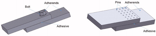
Hybrid bonded-fastening (HBF) joints
A hybrid joint is the combination of adhesive bonding and mechanical fastening. Loads are shared both by the metallic part of mechanical fastening and the adhesive joint. As the hybrid joints exhibit high static strength and long fatigue life, they are preferably used in advanced structures in aeronautics, marines and automotive applications. Hybrid bonded fastening (HBF) joints are divided into two major categories
(A) Hybrid bonded-bolted (HBB) joints, and
(B) Hybrid bonded pinned (HBP) joints.
An example of both joints is shown in .
Figure 6. Types of hybrid bonded-fastening (HBF) joints.
The main concern in the hybrid joint is the mechanism of load sharing between the adhesive bonding and mechanical fastening. Kelly investigated the comparison between hybrid joints and adhesive joints, where the structural performance of load sharing between the hybrid joints were discussed. Kelly characterized the load transfer in the hybrid joint using numerical simulation and measurement of the load transfer. The results showed that the hybrid joints showed improved fatigue life and joint strength compared to adhesively bonded joint demonstrated [Citation26,Citation27].
Hybrid bonded-bolted (HBB) joints
Kweon et al. [Citation9] investigated the failure loads of the HBB joints between aluminium and polymer composite. Comparison of joints prepared from mechanical joint, adhesive bonding and hybrid joint showed the following order
The limitation of HBB in composite structure is that the delamination and fibre damages occur in HBB joints between FRP and metals due to the manufacturing of bolt holes in FRP. Fabrication of HBB joint increases the manufacturing time and cost, as it requires longer curing time for the bonding process. The temperature increase during curing process causes thermal deformation in FRP which results in residual thermal stress. Highly accurate fit-up between adherend components becomes difficult, specifically for complex shaped structures of weight saving design. The co-curing method has been developed to overcome the above problems [Citation28–34].
Adhesive bonded joints are being used more often than the fasteners because of their improved joint properties. Matthews et al. [Citation35] reviewed the theoretical work, including classical and finite element methods related to all aspects of Hybrid bonded-bolted (HBB) joints in composite materials. Classical methods can perform linear and non-linear analysis, the latter accounting for material and geometric nonlinearity. The joint strength is improved when adherend stiffness is increased and adhesives modulus is lowered. In HBB joints, the ductile adhesive is prefered over brittle adhesive as the ductile adhesive improves static and fatigue strengths with reduced creep failure.
Vinson [Citation36] summarized his work dealing with the adhesive bonding of polymer matrix composite (PMC) structures and carried out analysis of joints like single-lap joints, double-lap joints, scarf joints, and stepped-lap joints under tension. He used a continuum model assuming adherends as isotropic or anisotropic & elastic, and the adhesive as elastic or elastic-plastic. Numerous computer codes are available for the design and analysis of bonded joints. In the analysis of bonded joints of HBB, adhesive material properties are considered as an important parameter for stress calculation [Citation37]. Volkersen introduced the new phenomenon called shear-lag (or differential shear) in single-lap joints under tension. The adherend effects were first taken into account by Goland and Reissner [Citation38].
Zuccarello et al. [Citation39] experimentally determined the mechanical and fatigue behaviour of double lap HBB joint. The study revealed that tensile failure is dominated by bonding, while the energy absorption is dominated by bolting. Energy absorption of Hybrid Bonded-Fastened (HBF) joint material significantly increases at the time of fracture, as this is important for mechanical structures that must be able to dissipate energy. However, Wohler curves indicated the fatigue failure in the hybrid bonded bolted joints. Before the failure of bonding, the bolt failure took place due to the effects of bolt preloaded that leads to a lowering of the maximum peeling stress. Fu et al. described that the performance of hybrid joints prepared with single lap joint geometry depend on the washer designs, because it provides the maximum clamping pressure over the entire overlap area of joints. FE analysis of adhesive joints showed reduced maximum peel stress at the adhesive-substrate interface which helped to improve joint performance [Citation23].
Dhanasekar et al. investigated the static analysis of bonded-bolted steel butt joints (using three dimensional finite element method) subjected to two step loading via pre-stress distribution loading and in-plane bending. The bonded butt joints are used in two categories of applications such as (i) the plate girders and building beams, (ii) pressure vessels and glued insulated rail joints. The FE joint model was meshed with 8 node 3 D solid continuum elements (C3D8R) by using ABAQUS. The simulated results revealed that the bonded butt joints made the bolts tension free and were more effective in joining the structures. Due to the looseness of the bolt in the bonded butt joint, the length of contact surface increases, which may gravely influence the structural behaviour of bonded-bolted butt joints [Citation40].
Load sharing in HBB joints
Load sharing is a nonlinear function of the composite design and many researchers used modelling approach to determine the parameters related to loading effect and the effect size [Citation27,Citation41–43]. Only very few experimental studies are comes out as there may be a substantial cost and time involved in production and also due to inconvenience in load sharing measurement. In HBB joint, the load sharing by the bolts refers to (a) Contact between the hole bearing surface and the bolt shank and (b) friction between the coordinated external surface and the bolt head/washer. The loading partition refers to the exterior ratio of bolt and adhesive [Citation27]. Kelly stated that load sharing is a necessary mechanism by which the stiffness of an HBB joint can be improved beyond the basic joints and crack openings can be delayed [Citation26]. On the other hand, Graham et al. stated that such an approach is equivalent to regulated joint design. Instead, the possibility of a badly designed joint should to be considered and determined against the existing bonded joint and bolt joint. The design procedures could in fact, prove to be really a functional HBB design. Such a situation can only be considered, in the event of significant load transfer [Citation44].
Adhesive strength in thin layered mortared concrete masonry
A comparative study on combined shear and compression tests of thin layer mortared concrete masonry and grouted masonry for the bed joints having five different orientations was reported by Dhanasekar et al. [Citation45]. It was observed that different shear to compression loads on the joints lead to failure of thin layer polymer mortared masonry. They observed that the maximum compressive strength was observed in the bed joint oriented perpendicular to the direction of applied loads. In thin mortar layered masonry, the compression failure took place at 85% of the load and the loads were almost linearly elastic. When compared to the grouted masonry, the joint strength of thin layered masonry was influenced by the loading directions and different bed joint orientations and joint thickness. The bond strength was also influenced by the curing and ageing conditions. In mortared concrete masonry, some of the bond characteristics such as the integrity, serviceability, in-plane shear and out-of-plane shear, and flexural strength of masonry walls are considered to be important for structural application. Increase in shear bond strength leads to an increase in flexural strength up to the bending stress. In comparison with wet cured specimens, the dry cured specimens exhibited maximum bond strength, high young’s and shear modulus of thin layered mortared masonry. Thin layered concrete mortared masonry showed the bond strength twice than that of conventional masonry [Citation46].
Adhesive thickness effect
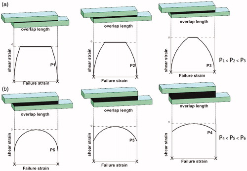
Silva et al. investigated the linear analysis of single-lap joints of hybrid bonding having variable adhesive thickness ranging from between 0.2mm and 1 mm. They found that in joints having 0.2mm thickness, the yielding was localised at the ends of the overlap because the peak strain reached the failure strain of adhesive. However, for 0.5mm and 1 mm adhesive thicknesses, more uniform stress distribution was observed allowing yielding to spread more inside the overlap and global yielding. Global yielding occurred before the adhesive peak strain at the ends of the overlap to reach the adhesive failure strain. For thin bond lines, the effect of stress concentration at the ends of the overlap is more important than the effect of yield spreading and the joint strength prediction increases with adhesive thickness. In thin bond lines, the increase of bond thickness lead to increase of failure load i.e. P1 < P2 < P3 (as shown in ). As the adhesive thickness increases with thick bond lines where global yielding occurs, the joint strength prediction decreases because the effect of yield spreading which is vital compare to the effect of the stress concentration at the ends of the overlap. Similarly, the increase of bond thickness leads to decrease of failure load i.e., P4 < P5 < P6 (as shown in ) as in thicker bond lines, the stress distribution is more uniform along the overlap and global yielding of the overlap occurs for a lower load [Citation47].
Figure 7. Schematic of adhesive plastic shear strain distribution along the overlap as a function of adhesive thickness for (a) thin bond lines and (b) thick bond lines.
Adhesive joint failures in composites
The failure in the hybrid adhesive joint may happen due to various reasons including the conditions of bonding process. The co-cured lap joint prepare with the adhesive film showed lower joint strength due to delamination failure compared to joint prepared by secondary bonding process in spite of high material strength and good adhesion performance of adhesive. Absence of delamination in the composite prepared by secondary bonding process is due to early failure through crack growth propagation in the adhesive layer. Moreover, failure strength of composite bonded joints not only depends on material strength but also depends on adhesion performance of the adhesive due to the delamination failure in composite materials [Citation48]. The performance of bonded single lap joints between cross-ply adherends with different stacking sequences ranging between 0° and 90° were experimentally investigated by Kairouz et al. [Citation49] and a large range of laminate lay-ups were considered. In 0° surface ply, the failure was initiated by a crack in the ply next to fillet root and the joint strength was increased with increase in bending stiffness and the ratio of overlap length to adherend thickness. And in 90° surface layer the failure was initiated by a transverse crack in the ply next to fillet tip and shear cracking along the interface of both orientations, and the joint strength was increased with a decrease in bending stiffness and ratio of overlap length to adherend thickness.
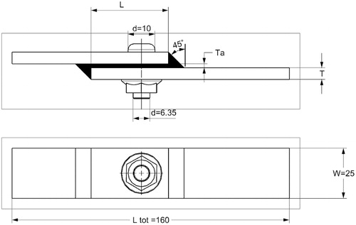
Single-lap joints of hybrid bonded/bolted composite as shown in , can give an incremental structural performance in load transfer compared to adhesive bonding as identified by Kelly [Citation27]. A finite element model was developed in ABAQUS and the adherends were modelled using linear brick elements enhanced with incompatible modes to improve the performance of the elements in bending.
Figure 8. ASTM D638-02a standard dimension of hybrid single-lap joints.
The adhesive was modeled using fully integrated eight-node brick elements. The mesh was refined adjacent to the hole and at the overlap ends and a coarser mesh was used in regions further afield from the overlap. The material properties of carbon fibre/epoxy (T700/Epicote 828LV) laminates was taken for the analysis of the adherends having [0/45/90/-45]sn laminate stacking sequence. The effects of adherend thickness, adhesive thickness, overlap length, bolt pitch distance and adhesive modulus on the performance of laminate were investigated. The clearance between the bolt and the hole delays the load transfer to the bolt and subsequently delays the performance of the joint. The results from this study can be summarized as the load transferred by the bolt increases with increasing adherend and adhesive thickness. The load transferred by the bolt decreases with increasing overlap length, pitch distance and adhesive modulus.
Da Silva et al. [Citation47] studied the analytical model of adhesively bonded joints and the failure criterion for linear, nonlinear, elastic analysis for such joints are reported in .
Table 3. Failure criteria used for models [Citation47].
Chan et al. [Citation50] focused on the stress distributions in laminated composite joints with multiple pin loads using finite element analysis and investigated the use of hybrid joints in structural repair. It is infer as from their work that the performance of single lap joints is sensitive to factors like ply stacking sequence of laminate, bonding surface preparation, anisotropic nature of adherend, as well as bearing and load transfer from one adherend to the other. The configuration of the bonded-bolted joint is shown in .
Figure 9. Hybrid joint configuration.
The above Figure shows that two bolts are used in the overlap region of a single strap joint with Carbon Fibre Reinforced Polymer (CFRP) adherends. Each laminate ply was modeled using SOLID45–eight-node brick elements in ANSYS and the gap in the form of hole/pin at the interface between the parent and repair laminates was modelled using a three-dimensional non-linear contact element, CONTAC49. For both parent and repair laminates, a negligible compressive stress was observed between the two holes. The results imply that the bolts do not take an active role in load transfer before the initiation of failure. However, the bolts in the bonded-bolted joint actually reduce in-plane axial stress near the edge of overlap [Citation50].
Investigation by Lee et al. [Citation51] on the joint strengths, peel stresses and failure modes in double-strap adhesive joint and supported single lap GFRP (Glass fibre reinforced polymer) joints showed that the load carrying capacity of double strap joints was better that of supported single-lap joints. Comparison of load-displacement results and joint strength of supported single-lap joints with double-strap joints indicated that the peel stresses are greater in supported single-lap joints compared to double-strap joints, and the failure behaviour of adhesively bonded joints was carried over by peeling effect. Most of the specimens exhibited the thin-layer cohesive failure pattern or the light fibre tear failure pattern as shown in .
Figure 10. Typical failure during the test: (a) TLC failure, (b) LFT failure.
To understand and predict the adhesive joint failures in a single lap joint bonded with different adhesives, Silva et al. [Citation52] carried out experiments with lap joints using ductile and brittle adhesives and joints having different overlap lengths to predict the strength of joints. In the brittle adhesive, the analytical model of Hart-Smith and numerical methods of Cohesive Zone Model (CZM) were used to predict the failure load in the composites. The analysis indicated that brittle adhesive joint has satisfactory joint strength values. In ductile adhesive, the global yield criterion has yielded better results. Silva et al. observed that numerical models were capable of simulating the failure initiation and crack propagation.
Kweon et al. [Citation53] carried out experiment by selecting different fabrication methods, variable adherend thickness, varying overlap length, different types of lay-up pattern on the failure load and strength of composite to composite bonded single-lap joints and aluminium to composite bonded single lap joints. They have also carried out three dimensional finite element analysis to determine the stress distributions for different type of joint geometries [Citation54]. It was found that the joint strength decreases in larger overlap length and increases in thicker adherend joints and the secondary bonded joints had higher strength than the co-bonded. The inter-laminar stresses and failure loads are affected by changing the stacking sequence in the laminate.
Matthews et al. [Citation55] studies the effect of change of stacking sequence on joint strength of adhesively bonded carbon fibre composite having variation in angle of layup ranging between 0 and/±45°. It was observed that the failure load increase with increasing the ratio of overlap length to adherend thickness. Bodjona et al. [Citation56] reviewed the hybrid bonded fastening joints and their applications in composite structures covering the experimental research, an analytical and numerical model of both joints, the design and manufacture of hybrid bonded bolted (HBB) joints and the hybrid bonded pinned (HBP) joint as detailed in .
Table 4. Quasi-static strength and energy absorption improvements (pinned versus unpinned) reported in the HBP literature [Citation56].
An experiment on the joint strength of two similar as well as dissimilar materials such as carbon-carbon composites (similar materials), carbon-carbon-silicon carbide composites (dissimilar materials) and titanium alloy substrate (dissimilar materials) in various combination bonded in over-lap joint and single-lap joints under shear loads exhibited the strong bond strength of joints. The single lap joint of C/C and C/C-SiC substrates give maximum joint strength than that of other substrates like C/C-SiC-C/C-SiC, C/C-SiC-C/C, C/C-C/C, C/C-SiC-titanium, C/C-titanium, and titanium-titanium. The overlap joint of Ti-Ti substrate combines another synchronous and stronger strength than the combined strength of the single lap joint of similar combination. However, adhesive bonded joints of metal to composite and metal to metal resulted in superior value than some other types of substrates owing to difference in stiffness of substrates [Citation57].
Joint failures in masonry walls reinforcements
The failure mode in out-of-plane deformation of unreinforced masonry, confined masonry, internal reinforced masonry and external surface reinforced masonry walls of masonry wall composite structures are described with explicit finite element (EFE) model method [Citation58]. The developed EFE model was used to determine the method of retrofitting of unreinforced clay brick walls. The study predicted that the performance of unreinforced masonry walls increase up on incorporating internal as well as external surface reinforcement. In-plane shear deformation of masonry walls with higher bond strengths were also examined and the shear walls were built with high bond strength polymer cement mortar. The micro finite element modelled for higher the bond strength composite showed occurrence of pre-compression up on loading that has negative effect on the safety of the high bond strength unreinforced masonry shear walls. The study concluded that the increase in the bond strength increased the in-plane shear of the masonry walls significantly [Citation59].
Adhesive butt-joint geometries
The butt joint design configuration is based on the ability of the adhesive to withstand tensile stresses developed during the tension loading of the adherents. The major drawback in using butt joints is their inability to withstand bending forces since the adhesive would experience cleavage stresses. Another drawback is the difficulty to align the two adherents during the joining of substrate in butt joint. Butt joints are in general seldom used in composite-to metal or composite-to-composite bonding where thin skins are involved [Citation13]. Butt joint can be improved by redesigning then in number of ways. Any modification of the simple butt joint is oriented towards reducing cleavage effects caused by side loading.
Mixed adhesives joints
Recently, multi-adhesive based bonding techniques are widely studied and validated for this potential usefulness in improving joint strength. The concept is to increase the joint performance by including two or more adhesives in the bond line (). In this technique, the overlap region has more flexible adhesive and the centre region has a rigid one [Citation60–63].
Figure 11. Single lap joint with four different adhesives.
Breto et al. [Citation64] studied the numerical models of tri material singularities of mixed adhesive joints and considered characterization and treatment of these types of singularities. Firstly, adhesive material was placed in between two joints for attaining the single behaviour at the tri material singularities. Next, the finite element model was demonstrated by the convergence of the continuum transition technique. Finally, the results achieved the best mesh convergence in FE models and the optimum material transition.
Auxetic materials are a modern class of materials having different microstructure and find wide applications in building construction, sports safety equipment, defense equipment, etc. In the area of building and construction material applications, the effect of negative Poisson’s ratio (NPR) behaviour of auxetic foam composites on strength properties was experimentally evaluated and compared with the polymer cement mortar composites reinforced with fiberglass mesh layers exhibiting positive Poisson’s ratio. In the auxetic foam composite, the thickness of mortar was higher than that of auxetic foam thickness. This has lead to increase in compressive strength of the auxetic foam composite. However, fibre glass mesh composite showed high strength than that of auxetic foam composite. The delamination failure takes place only in fiberglass composites, where as it was not observed in auxetic foam composites [Citation65].
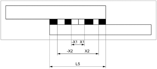
Compaction process of multiple adhesive joints
The poor and inefficient bonding design lead to joint, having non uniform stress distribution resulting in failure of joint at the early stage [Citation66,Citation67]. This limitation can be reduced by combining different adhesive materials that have different mechanical properties along the bond line. Use of multiadhesive technology increases the performance of the joints in terms of the ultimate load compare to the joints prepare from simple adhesive [Citation60,Citation61]. Two different approaches to the adhesive area are taken into account. The first one is similar to the continuous function of describing the adhesive characteristics and the material attributes vary gradually as described by Carbas [Citation62] and the performance of adhesive has more than 60%. In the second, the most common, distribution has a banded form as described by Stapleton [Citation63] and Ozer [Citation68]. Ruben Breto et al. analysed a quality based technique built on the properties of single lap joint using the mixed resin approach (banded shape). In addition, the compaction process effect in the joint structural response also analysed for adhesive distribution, joint assembly bearing capacity. The compaction process effect includes the structural analysis of assembly joint, a computational fluid-dynamic model capable of integrating different resins along the bondline has been developed. A special device has been designed for manufacturing such joints and the different parts of this adhesive dispenser device are described in [Citation69].
Figure 12. Adhesive dispenser device flowchart for manufacturing 5-bands test specimens.
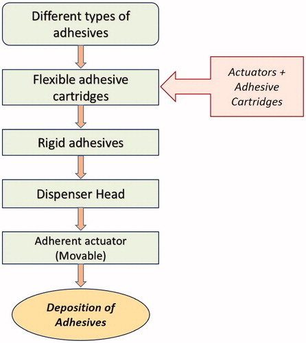
This approach is quite useful for obtaining precision in the manufacturing tolerances and facilitates the adhesive deposition task.
The potential improvement of the grading technique applied to adhesive joints has been proved using the adhesive mixing approach. The joint manufacturing with a special device designed only for this purpose is require that will helps to maintain the manufacturing tolerances under control. It has been proved that distributions of initial optimal materials depend on the compaction process. The banded configuration has been experimentally validated through joint tests that exhibits an increase in ultimate load up to 70% with respect to the base adhesives assemblies [Citation69].
Perspectives
The purpose of the joint is to create strong bond between substrate and transfer loads from one adherent to another smoothly and uniformly in a mechanical structure, most of the failure usually originates from the joint area. The failure stresses in mechanical joints such as bearing stress, shearout stress, net section stress and transverse splitting stress were reviewed by many researchers. These four relevant stresses are considered by the joint designers for manufacture of joints having improved performance. These joint failures are mostly absent in the adhesive bonded joints as they possess excellent distribution of loads over a much wider area than the mechanical joints.
Adhesive bonding is the preferred bonding method to join both metallic and non-metallic structures with the advantages of low interlaminar shear, and high tensile strength. Polymeric adhesives are used to join large variety of material combinations including metal-metal, metal-plastic, metal-composite, composite-composite, plastic-plastic, metal-ceramic systems, etc. The failure criteria depends on the joint designs and type of joints. The composite bonded joint analysis is able to predict the failures of adhesives such as adhesive - adherent interface, within the surface plies of the laminate, and most importantly accounted for non-linear material behaviour. The literatures in this area have been reviewed for the Hybrid Bonded Bolted (HBB) joint and Hybrid Bonded Fastening (HBF) joint techniques. HBF technique has the ability to delay the crack initiation in lap joints. In the hybrid joints, the failure of tensile strength is dominated by bonding, while the energy absorption is dominated by bolting. More researchers are underway to elucidate the mechanism of load transfer, stress distribution, mode of joint failure. Numerical methods and finite element computer analysis and simulation studies have given lot of opportunities to design the joint to withstand the further structures effectively and efficiently to studies on influence of external parameters on joint strength is well documented and provide information on selection of proper adhesive for correct application. The review sees lot of scope for research activities in this subject area.
Conclusion
Adhesive joining is considered as an alternate method to traditional joining methods due to many advantages. Adhesive joints are used in lightweight composite structures owing to homogeneous stress distribution, low cost, ease of bonding, etc. As the light weight and complex composite structures are used in variety of applications in aeronautical, aerospace and automotive and industries, its popularity is increasing manufacturability of lighter, safer and more efficient vehicles. The potency of the adhesive bonding method and the influence of parameters such as the composition of the adhesive, surface pre-treatment method, surface preparation materials, adhesive lay-up procedure, tooling, and curing process are explained in detail. The comparison of adhesive joints between metal to metal and metal to composite revealed that adhesive bond strength is better in heterogeneous substrate than that of similar substrates (metals & composites) due to unbalanced stiffness. Mixed adhesive system shows promising properties to keep the manufacturing tolerances under control.
Generally, the load transfer in single-lap joints of hybrid bonded/bolted joint can give the incremental structural performance in comparison with adhesive joint. The stiffness of HBB/HBF joint can be improved better than the basic joints with a delayed crack openings. A HyperSizer analysis software is found to be more useful compared to conventional analysis software in analysing and simulating the bonded joint. This structural analysis software is more capable of handling various joint geometries, linear and nonlinear adhesives, asymmetric and unbalanced laminates, various loading and boundary conditions. This analysis software is helpful in devising techniques to increase the joint performance and to reduce the weight of structure. This paper reviews in detail the recent developments in the usage of adhesively bonded joints and adhesive bonding techniques for various applications such as automobile, aeronautical, building and construction. The overview of adhesive joints, hybrid bonded-bolted joints and mortared joints are explained in a clearer and simpler way for the betterment of the researchers working in this field.
References
- Singh NB, Sarita R, Sonal A. Polymer nanocomposites and Cr (VI) removal from water. Nanosci Technol. 2014;1:10.
- Hull D, Clyne TW. An introduction to composite materials. 2nd ed. New York: Cambridge University Press; 1996.
- Cabral TD. A first approach to structural health monitoring of adhesive bonded joints in pipelines using integrated fiber optic sensors [Thesis]. University of Campinas; 2016.
- Rezende MC. Fractography of structural composites. Polymers. 2007;17:E4–E11.
- James KK. Structural adhesives and bonding. Proceedings of the Structural Adhesives Bonding Conference, arranged by Technology Conference Associates, El Segundo, 1979; California.
- Zitoune R, Collombet F. Numerical prediction of the thrust force responsible of delamination during the drilling of the long-fibre composite structures. Compos A. 2007;38:858–866.
- Davim JP, Reis P, António CC. Drilling fiber reinforced plastics (FRP) manufactured by hand lay-up: influence of matrix (Viapal VUP 9731 and ATLAC 382-05). J Mater Process Technol. 2004;155–156:1828–1833.
- Matsuzaki R, Shibata M, Todoroki A. Improving performance of GFRP/aluminum single lap joints using bolted/co-cured hybrid method. Compos A. 2008;39:154–163.
- Kweon JH, Jung JW, Kim TH, et al. Failure of carbon composite-to-aluminum joints with combined mechanical fastening and adhesive bonding. Compos Struct. 2006;75:192–198.
- Mouritz AP, Gellert E, Burchill P, et al. Review of advanced composite structures for naval ships and submarines. Compos Struct. 2001;53:21–42.
- Davim JP, Reis P, Antonio CC. Experimental study of drilling glass fiber reinforced plastics (GFRP) manufactured by hand lay-up. Compos Sci Technol. 2004;64:289–297.
- Banea MD, Da Silva LF. Adhesively bonded joints in composite materials: an overview. Proc IMECHE. 2009;223:1–18.
- Adams RD, Comyn J, Wake WC. 1997. Structural adhesive joints in engineering. London: Chapman & Hall.
- Division – 3M Industrial adhesives and tapes. Choosing and using a structural adhesive white paper; 2002.
- Anyfantis KN, Tsouvalis NG. The effect of surface preparation on the effect of double strap adhesive joints with thick steel adherents. 2nd International Conference on Marine Structures - Analysis and Design of Marine Structures. Lisbon, Portugal; 2009.
- Bishop J. Handbook of adhesives and sealants. New York: McGraw Hill Inc.; 2005.
- Morais BA, Pereira BA, Teixeira PJ, et al. Strength of epoxy adhesive bonded stainless-steel joints. Int J Adhes Adhes. 2007; 27:679–686.
- Shahid M, Hashim AS. Effect of surface roughness on the strength of cleavage joints. Int J Adhes Adhes. 2002;22:235–244.
- Zahra T, Dhanasekar M. Characterisation and strategies for mitigation of the contact surface unevenness in dry-stack masonry. Constr Build Mater. 2018; 169:612–628.
- Allen KW. At forty cometh understanding. A review of some basics of adhesion over the past four decades. Int J Adhes Adhes. 2003; 23:87–93.
- Peters ST. Handbook of composites. London: Chapman & Hall; 1998.
- Camanho PP, Tavares CML, De Oliveira R, et al. Increasing the efficiency of composite single-shear lap joints using bonded inserts. Composites Part B. 2005; 36:372–383.
- Fu M, Mallick PK. Fatigue of hybrid (adhesive/bolted) joints in SRIM composites. Int J Adhes Adhes. 2001; 21:145–159.
- Gomez S, Onoro J, Pecharroman J. A simple mechanical model of a structural hybrid adhesive/riveted single lap joint. Int J Adhes Adhes. 2007; 27:263–267.
- Hart-Smith L. Bonded-bolted composite joints. J Aircr. 1985; 22:993–1000.
- Kelly G. Quasi-static strength and fatigue life of hybrid (bonded/bolted) composite single-lap joints. Compos Struct. 2006; 72:119–129.
- Kelly G. Load transfer in hybrid (bonded/bolted) composite single-lap joints. Compos Struct. 2005; 69:35–43.
- Kim HS, Lee SJ, Lee DG. Development of a strength model for the cocured stepped lap joints under tensile loading. Compos Struct. 1995; 32:593–600.
- Huang CK. Study on co-cured composite panels with blade-shaped stiffeners. Compos A. 2003; 34:403–410.
- Shin KC, Lim JO, Lee JJ. The manufacturing process of co-cured single and double lap joints and evaluation of the load-bearing capacities of co-cured joints. J Mater Process Technol. 2003; 138:89–96.
- Kim HS, Park SW, Lee DG. Smart cure cycle with cooling and reheating for co-cure bonded steel/carbon epoxy composite hybrid structures for reducing thermal residual stress. Compos A. 2006; 37:1708–1721.
- Olivier P, Cottu JP. Optimisation of the co-curing of two different composites with the aim of minimizing residual curing stress levels. Compos Sci Technol. 1998; 58:645–651.
- Park SW, Kim HS, Lee DG. Optimum design of the co-cured double lap joint composed of aluminum and carbon epoxy composite. Compos Struct. 2006; 75:289–297.
- Shin KC, Lee JJ. Effects of thermal residual stresses on failure of co-cured lap joints with steel and carbon fiber–epoxy composite adherends under static and fatigue tensile loads. Compos A. 2006; 37:476–487.
- Matthews FL, Kilty PF, Godwin EW. A review of the strength of joints in fibre-reinforced plastics. Part 2. Adhesively bonded joints. Composites. 1982; 13:29–37.
- Vinson JR. Adhesive bonding of polymer composites. Polym Eng Sci. 1989; 29:1325–1331.
- Volkersen O. Rivet strength distribution in tensile-stressed rivet joints with constant cross-section. Luftfahrforschung. 1938; 15:41–47.
- Goland M, Reissner E. The stresses in cemented joints. Trans ASME, J Appl Mech. 1944; 66:A17–A27.
- Zuccarello B, Di Franco G, Inserillo M. An experimental study of GFRP-aluminium bolted bonded joints, ECCM15 - 15TH European Conference on Composite Materials; Venice, Italy; 2012.
- Ding K, Dhanasekar M. Flexural behaviour of bonded-bolted butt joints due to bolt looseness. Adv Eng Softw. 2007; 38:598–606.
- Paroissien E, Sartor M, Huet J, et al. Hybrid (bolted/bonded) joints applied to aeronautic parts: analytical two-dimensional model of a single-lap joint. J Aircr. 2007; 44:573–582.
- Bodjona K, Raju K, Lim G-H, et al. Load sharing in single lap bonded/bolted composite joints. Part I: model development and validation. Compos Struct. 2015; 129:268–275.
- Bodjona K, Lessard L. Load sharing in single-lap bonded/bolted composite joints. Part II: global sensitivity analysis. Compos Struct. 2015; 129:276–283.
- Graham DP, Rezai A, Baker D, et al. The development and scalability of a high strength, damage tolerant, hybrid joining scheme for composite-metal structures. Compos A. 2014; 64:11–24.
- Thamboo JA, Dhanasekar M. Behaviour of thin layer mortared concrete masonry under combined shear and compression. Aust J Struct Eng. 2016; 17:39–52.
- Thamboo JA, Dhanasekar M. Characterisation of thin layer polymer cement mortared concrete masonry bond. Constr Build Mater. 2015; 82:71–80.
- da Silva LFM, das Neves PJC, Adams RD, et al. Analytical models of adhesively bonded joints—Part II: comparative study. Int J Adhes Adhes. 2009; 29:331–341.
- Kwang-Soo K, Jae-Seok Y, Jae-Mo A, et al. Failure mode and strength of unidirectional composite single lap bonded joints I. Experiments. Compos Res. 2004;17:14–21. Volume Issue
- Kairouz KC, Matthews FL. Strength and failure modes of bonded single lap joints between cross-ply adherends. Composites. 1993; 24:475.
- Chan WS, Vedhagiri S. Analysis of composite bolted/bonded joints used in repairing. J Compos Mater. 2001; 35:1045–1061.
- Lee HK, Pyo SH, Kim BR. On joint strengths, peel stresses and failure modes in adhesively bonded double-strap and supported single-lap GFRP joints. Compos Struct. 2009; 87:44–54.
- Neto JABP, Campilho RDSG, da Silva LFM. Parametric study of adhesive joints with composites. Int J Adhes Adhes. 2012; 37:96–101.
- Kweon J-H, Song M-G, Choi J-H, et al. Effect of manufacturing methods on the shear strength of composite single-lap bonded joints. Compos Struct. 2010; 92:2194–2202.
- Kweon J-H, Seong M-S, Kim T-H, et al. A parametric study on the failure of bonded single-lap joints of carbon composite and aluminium. Compos Struct. 2008; 86:135–145.
- Matthews FL, Tester TT. The influence of stacking sequence on the strength of bonded CFRP single lap joints. Int J Adhes Adhes. 1985; 5:13–18.
- Bodjona K, Lessard L. Hybrid bonded-fastened joints and their application in composite structures: a general review. J Reinf Plast Compos. 2016; 35:764–781.
- Srivastava VK, Singh S. Adhesive bonded single lap and over-lap joints of C/C, C/C-SiC composites and titanium alloy. J Mech Eng Res. 2011; 3:162–167.
- Noor-E-Khuda S, Dhanasekar M, Thambiratnam DP. Out-of-plane deformation and failure of masonry walls with various forms of reinforcement. Compos Struct. 2016; 140:262–277.
- Dhanasekar M, Thamboo JA, Nazir S. On the in-plane shear response of the high bond strength concrete masonry walls. Mater Struct. 2017; 50:214.
- Fitton MD, Broughton JG. Variable modulus adhesives: an approach to optimised joint performance. Int J Adhes Adhes. 2005; 25:329–336.
- Da Silva LFM, Lopes MJCQ. Joint strength optimization by the mixed-adhesive technique. Int J Adhes Adhes. 2009; 29:509–514.
- Carbas RJC, da Silva LFM, Critchlow GW. Adhesively bonded functionally graded joints by induction heating. Int J Adhes Adhes. 2014; 48:110–118.
- Stapleton SE, Waas AM, Arnold SM. Functionally graded adhesives for composite joints. Int J Adhes Adhes. 2012; 35:36–49.
- Breto R, Chiminelli A, Lizaranzu M, et al. Study of the singular term in mixed adhesive joints. Int J Adhes Adhes. 2017; 76:11–16.
- Zahra T, Dhanasekar M. Characterisation of cementitious polymer mortar–Auxetic foam composites. Constr Build Mater. 2017; 147:143–159.
- Li G, Lee-Sullivan P, Thring RW. Nonlinear finite element analysis of stress and strain distributions across the adhesive thickness in composite single-lap joints. Compos Struct. 1999; 46:395–403.
- Reis PNB, Antunes FJV, Ferreira JAM. Influence of superposition length on mechanical resistance of single-lap adhesive joints. Compos Struct. 2005; 67:125–133.
- Özer H, Öz O. Three dimensional finite element analysis of bi-adhesively bonded double lap joint. Int J Adhes Adhes. 2012; 37:50–55.
- Breto R, Chiminelli A, Izquierdo S, et al. Analysis of mixed adhesive joints considering the compaction process. Int J Adhes Adhes. 2017; 76:3–10.