
 ?Mathematical formulae have been encoded as MathML and are displayed in this HTML version using MathJax in order to improve their display. Uncheck the box to turn MathJax off. This feature requires Javascript. Click on a formula to zoom.
Abstract
The aim of this paper is to solve the problem of extremely difficult, low work efficiency and low accuracy of finite element analysis (FEA) when considering the bond-slip performance of recycled aggregate concrete filled circular steel tube (RACFCST). Toward this end, spring elements generation software for RACFCST V1.0, parametric modeling software for push-out test of RACFCST V1.0, and the Nodes selection program for RACFCST were developed. The FEA model of the RACFCST push-out test was established with the software and the model was calculated in ABAQUS, the calculated results were compared with the existing test results. The results show that: (1) The FEA model of RACFCST components considering bond-slip can be efficiently, accurately and simply established by spring elements generation software for RACFCST V1.0; (2) The results of FEA were found to be in good agreement with the experimental data, and spring elements generation software can solve the problem of FEA of RACFCST considering bond-slip performance; (3) The modeling efficiency and accuracy of RACFCST components can be greatly improved by Parametric modeling software for push-out test of RACFCST V1.0; (4) The efficiency and flexibility of selecting nodes during post-processing is greatly improved by Nodes selection program for RACFCST V1.0.
1. Introduction
In recent years, as environmental awareness has increased in various countries, scholars in the civil engineering field have focused on the reuse of construction waste. Among the construction wastes, recycled aggregate concrete (RAC) has been studied by a large number of scholars because of its advantages in environmental protection and energy conservation [Citation1–5], and they attempted to apply RAC to civil engineering structures. However, the application of RAC is limited by the fact that the mechanical properties of RAC are worse than natural aggregate concrete, and especially the shrinkage is higher than the natural aggregate concrete [Citation6–11]. In order to solve the problems in the application of RAC, scholars draw on the principle and advantages of the two materials in the concrete-filled steel tube (CFST) [Citation12–18], the recycled aggregate concrete-filled steel tube (RACFST) structure has been proposed by scholars in various countries[Citation19], the RAC is placed inside the steel tube to form a composite structure, which not only has the advantages of the CFST, but also has relieved the limitation that RAC can only be applied to members of non-structural and expand the application prospects of RAC.
The performance of RACFST structure is seriously affected by the bonding property between RAC and the steel tube. Scholars have carried out some research on the bond-slip performance, and obtained important conclusions such as the basic theory of bond-slip performance and bond-slip constitutive. Chen Zongping et al. [Citation20–28] carried out the test of the RACFST column, the effects of the replacement ratio, strength grade and embedding length of the recycled aggregate on the bond-slip performance was analyzed and the calculation formula of the bond strength was obtained through the test. What needs to be emphasized is that all researchers have pointed out that the experimental study can provide a basic theory for the finite element analysis (FEA) of RACFST structures, although many scholars have obtained important theoretical results such as bond-slip constitutive relations. However, the FEA of RACFST considering bond-slip performance is so complicated that it cannot be applied to the FEA of RACFST members or structures, therefore, the bond-slip performance between the two materials is not considered when static or dynamic FEA of RACFST members and structures is carried out in most existing literature [Citation29–31].
In the field of civil engineering, the FEA of bond-slip performance begins with reinforced concrete (RC) structures. In the finite element model (FEM) of RC structures, the researchers’ methods of dealing with interface can be classified into two categories: (1) Most researchers do not consider the bond-slip behavior between steel reinforcement and concrete [Citation32–41]. They use embedded methods or shared node methods to assume that the steel reinforcement and concrete are perfectly bonded, which is obviously flawed. (2) However, very few researchers have considered the bond-slip properties between reinforced concrete in the FEM. For example, Hawileh et al. [Citation42–45] used the COMBIN14 spring element in ANSYS to consider the bond-slip behavior between steel reinforcement and concrete, and the effectiveness of the spring element has also been proven by their research. And Kalfat and Al-Mahaidi proposed two methods of using interface element and adhesive to consider the bond between CFRP and concrete (adhesive is connected to concrete and FRP, respectively) [Citation46,Citation47].
For the FEA of RACFST or CFST structures, the methods of FEM can be classified into categories: (1) most researchers assumed that the steel tube and concrete are perfectly bonded [Citation29–31]. (2) There are also a few scholars who use the Coulomb friction model to consider the bond-slip performance, For example, the Coulomb friction model was used to simulate the bond-slip performance of the interface between the two materials and the friction coefficient was set to 0.6 by Sun Xiaoling [Citation48] when she used ABAQUS to perform FEA on walled CFST column, and Wang Xiantie et al. [Citation49–52] used the same method as Sun Xiaoling when they considered the interface between steel tube and concrete. However, it is known that the friction force is only one of the components of the adhesive force according to the mechanism of the bond-slip performance, and it is not appropriate to use the frictional force instead of the bond-slip behavior of the surface of the two materials. If the bond-slip performance was not considered or the Coulomb friction model is used to consider the bond-slip performance, the bond-slip performance of the interface cannot be accurately described. These methods will lead to congenital defects in the FEA of such structures. (3) Few researchers [Citation53–54] used the cohesive element to simulate the bond behavior between steel tube and concrete. (4) Very few researchers used the spring element in ANSYS or ABAQUS to consider the bond-slip behavior between steel tube and concrete [Citation55–56], and almost all are not accurate enough due to the difficulty of the application of the spring element. Methods that can be used to simulate bond-slip performance include spring element and cohesive element, but due to the huge workload and difficulty of operation in ABAQUS, scholars cannot easily and correctly use these methods. Difficulties in applying cohesive element and spring element will be discussed in details in Section 2.
In addition to the problems in the setting of bond-slip for RACFST, these papers also have two defects in the FEA. Firstly, parameterized modeling for different specimens of the same test can greatly improve work efficiency and accuracy, however, none of them mentioned the method of parameterized modeling by programming means. Secondly, there are problems of difficult operation and low efficiency when selecting nodes in the model using the functionality provided by ABAQUS, however, there is no simple and accurate method for node selection in relevant literature.
The objective of this paper is to solve the above problems in the FEA of RAC filled circular steel tube (RACFCST). ABAQUS6.14 was selected for FEA in this paper, and the following research work is carried out in this paper:
To find an efficient and simple method that can consider bond-slip performance in FEA of RACFCST, This paper takes the push-out test as an example, spring element generation software for RACFCST V1.0 was developed through Python language. It is hoped that the work of this paper can solve the problem of large workload, complicated operation and low accuracy of FEA for RACFCST considering bond-slip performance.
To improve the efficiency and accuracy of modeling in the pre-processing, parametric modeling software of push-out test for RACFCST V1.0 was developed through Python language.
To improve the efficiency and flexibility of nodes selection in the post-processing, nodes selection program for RACFCST V1.0 was developed through Python language.
2. Difficulties in FEA of bond-slip performance
2.1. Cohesive and Spring2 element
The literature shows that the nonlinear spring element, cohesive element and Coulomb friction model in ABAQUS are used to simulate the bond-slip between steel (steel tube, section steel, steel bar) and concrete. However, it is difficult to determine the pressing force between the steel tube and the concrete, and it is known from the mechanism of the bond-slip that the friction force is only a part of the composition of the bonding force. Therefore, the nonlinear spring element and cohesive element are only introduced here. The parameters of the two elements are determined according to the bond-slip constitutive relationship obtained through the test. It is found that they have the following differences in simulating the bond-slip behavior through calculation and analysis:
Cohesive elements are used to simulate phenomena such as fractures. A separate layer is required for modeling to define the bond-slip performance and to connect with steel tube and concrete. Once the stress of the layer exceeds the cracking stress, the element stress will decrease to zero and fails. If all the cohesive elements fail in the model, the bond stress will be fully provided by friction and mechanical bite force. However, the friction force depends on the uncertain pressing force between the steel tube and the concrete, and the mechanical bite force cannot be accurately described. These two uncertain factors cause the cohesive element to fail to accurately describe the falling portion of the curve, and the P-S curve is affected by chemical adhesion, friction and mechanical bite force, if P-S curve is only defined as the properties of the cohesive element, it would be extremely inappropriate.
Spring2 element in ABAQUS is different from the cohesive element. If the P-S curve is completely defined as the nature of the nonlinear spring element, it will accurately describe the entire process of bond-slip, the reason is that the nonlinear spring element can also define a horizontal segment after the falling segment, instead of instantaneously dropping to zero as Cohesive passes the peak point. The horizontal section fully describes the friction and mechanical bite force, and does not require separate consideration of friction and mechanical bite after the chemical adhesion has completely disappeared. Therefore, spring2 element can not only better reflect the whole process of the curve, but also does not need to establish a separate bonding layer. In summary, the spring2 element is more suitable for simulating the bond-slip than the cohesive element.
There are three types of spring element in ABAQUS, namely spring1, spring2 and SpringA. Spring1 element is elastic spring element with only one node; Spring2 element is nonlinear spring element with two nodes, each node has only one degree of freedom; SpringA element is connected along two points, each point has three degrees of freedom. The F-D curve of spring2 element needs to be determined according to the relationship obtained by the test, D is equal to S and F is determined by the formula (1).
(1)
(1)
In the formula (1): Ai is the element area around the element node, as shown by the shading in , for example, the intermediate nodes’
Figure 1. Calculation method of Ai of spring element.
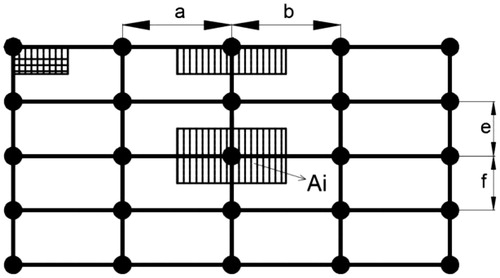
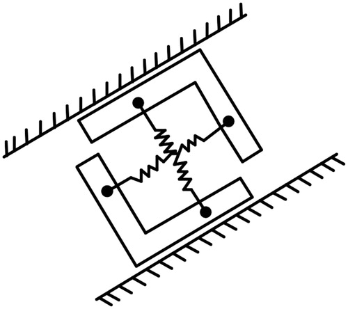
In the existing literature, the FEA of bond-slip is mostly for the simulation of reinforced concrete, since the steel bar has a small lateral dimension in the reinforced concrete member, so the double spring elements is used when applying the nonlinear spring element [Citation57–59], as shown in . However, the transverse dimension of the circular steel tube of the RACFCST is also large, in order to accord with the actual situation, it is necessary to consider setting the spring element in three directions, this paper proposes a three-spring elements model, which is provided with spring elements in three directions of each node. According to the actual force of the push-out test, the deformation of normal direction and the transverse tangential are derived from the deformation of the two materials under the force. The displacement values in these two directions are extremely small compared with the longitudinal interface slip displacement value. Therefore, linear spring element is used in the normal direction and the transverse tangential, and the stiffness of spring is set to the elastic modulus of the RAC with reference to the relevant literature; The longitudinal tangential direction (axial direction) is the direction of the bond-slip, so the nonlinear spring element is used in the longitudinal tangential, and the F-D curve of the nonlinear spring element is determined according to the push-out test.
Figure 2. Model of double spring elements.
2.2. Difficulties of spring element
Although the nonlinear spring elements is more suitable for analyzing the bond-slip behavior of RACFCST, but there are two major difficulties in application:
Only the linear spring elements can be added through the operation in the graphical user interface (GUI) of ABAQUS, however, the GUI operation of ABAQUS is also unable to add a large number of elastic spring elements, and the nonlinear spring elements can only be added by modifying the file with suffix inp;
Whether linear spring elements or nonlinear spring elements, it is necessary to find a large number of pairs of nodes on the steel tube and the RAC to define two nodes of the spring elements when defining spring elements. However, since the actual bond-slip is present at every point where the steel tube and the RAC are in contact, it is necessary to establish enough spring elements to be able to reflect the real situation. In order to simulate the actual bonding situation as much as possible, it is necessary to find more pairs of nodes on the basis of fine meshing. The difficulty of adding spring elements in RACFCST will be explained by a test specimen with a length of 410mm and a diameter of 67mm, when the mesh size of the test specimen is 10mm, there are 2,600 pairs of nodes in the RAC and steel tube at the interface. If the division is more elaborate or the spring element is applied to the actual structure, the difficulty is unimaginable. Obviously, the accuracy requirements of finite element analysis are inconsistent with the difficulty of adding actual spring elements, the spring elements are so difficult to add that the existing literatures almost do not consider the bond-slip of the interface when performing finite element simulation on the CFST or RACFCST structures, which will lead to insufficient comprehensive consideration of the FEA.
At present, even if the bond-slip performance is considered by adding nonlinear spring element in the literature, The method of adding nonlinear spring element is basically to manually find the number of two nodes belonging to the spring element through the GUI of ABAQUS, then the spring elements are manually added to the file with suffix inp according to the format required by ABAQUS, and the process of finding and modifying the file with suffix inp is difficult and error-prone. For example, Chi Jianjun et al. [Citation55–56] used nonlinear spring element to simulate the bonding performance between steel tube and concrete. The size of mesh is larger and the number of nodes is smaller, so that the spring elements can be added by direct search. However, such an approach makes the calculation accuracy lower, and the existing literatures do not mention the use of a programming method to add the huge number of spring elements.
3. Proposed FEM of bond-slip performance
3.1. Method of modeling
In order to solve the modeling problem of spring elements, the spring elements generation software for RACFCST V1.0 was developed by Python language in this paper. In addition, in order to improve the efficiency of modeling, parametric modeling software for push-out test of RACFCST V1.0 was developed. Python language was chosen for development of the software in this paper, the development of this software is based on the file with suffix inp of the ABAQUS model, and this file can be generated by the job option in ABAQUS. The file with suffix inp contains all the information about the entire finite element model, such as the name, geometry, material information, mesh, element, node information, load and boundary conditions of each part. The information in the file with the suffix inp is stored according to some certain rules, and these regularly stored information is the basis for the relevant secondary development [Citation60].
The method of FEM considering bond-slip performance is as follows:
Establishing the finite element model of RACFCST that does not consider the behavior of bond-slip and generate its file with the suffix inp;
Finding all the pairs of nodes of steel tube and concrete with the same coordinates in the file with the suffix inp by compiling the code in Python language;
Using the Python compiler to add the pairs of nodes to the file with the suffix inp according to the format and position requirements of ABAQUS for the nonlinear spring elements, at the same time, the
relationship obtained from the test is given to the nonlinear spring elements. Nonlinear spring elements were used in the longitudinal direction of the RACFCST, and linear springs were used in the normal direction and the transverse tangential direction because of the small deformation. The file with the suffix inp that added spring elements can be submitted directly to the ABAQUS job for calculation.
The step2 and step3 are implemented by the spring elements generation software for RACFCST V1.0. In addition, parametric modeling software is developed to avoid a large number of repeated operations and to facilitate the establishment of models for other specimens.
3.1.1. Development of spring elements generation software
The user interface of the spring elements generation software for RACFCST V1.0 is shown in .
Figure 3. Interface of spring elements generation software V1.0 for RACFCST.
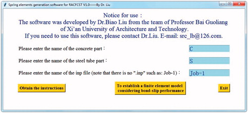
The use of this software requires only three steps:
Store and name the file with suffix inp of the finite element model without considering the bond-slip performance. Meanwhile, store the F-D curve of the spring element in the text and name it as FD.txt;
Put the file with suffix inp of previous step, FD.txt, and the spring elements generation software for RACFCST V1.0 in the same directory;
Run the spring elements generation software for RACFCST V1.0 and enter the parameters prompted in the user interface, as follows:
Enter the name of the RAC part in the ABAQUS model at the user interface;
Enter the name of the steel tube part in the user interface;
Enter the name of the file with the suffix inp that does not consider the bond-slip on the user interface.
After clicking the button-‘To establish a finite element model considering bond-slip performance’, the finite element modeling process considering the bond slip can be completed
What needs to be emphasized is that the input name is used to find the nodes of the part in file with suffix inp, so the name entered here must be the same as the part name in the ABAQUS model, otherwise the program will exit directly. After the three-step input is completed, the operation process of the program can be seen, and the new file with the suffix inp containing the spring elements will be generated after the operation is completed, This software names it NEWJob-1.inp by default. This new file with the suffix inp can be submitted directly to the job to complete the finite element analysis considering behavior of bond-slip.
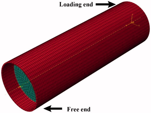
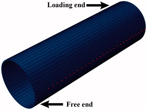
In this paper, the reliability of the FEA is verified by the push-out test of RACFCST by Xu Jinjun [Citation26], the FEM of those specimens in the literature [Citation26] is established by the software and the finite element models were calculated by ABAQUS, the schematic diagram of push-out test is shown in .
Figure 4. Schematic diagram for the push-out test.
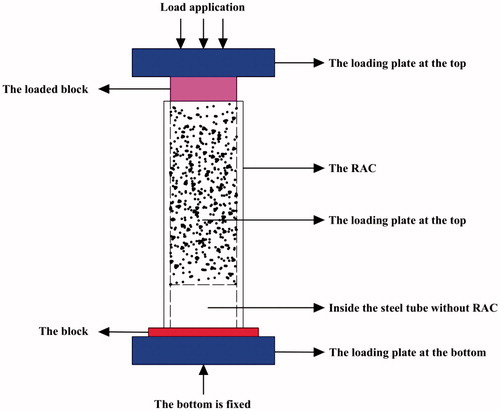
The top RAC and steel tube are aligned when the test specimen is designed, but the bottom RAC and steel tube have a certain height difference. In order to achieve the test purpose of pushing out the internal concrete, the specimen is placed on the loading device and only the internal RAC is loaded from the top through the loaded block on the RAC. The design of the test specimens is shown in the literature [Citation26]. The material properties of the steel tube and RAC are taken as the values measured in the literature [Citation26].
It should be emphasized that the focus of this paper is to verify the reliability of the software developed in this paper, in order to avoid errors due to the fitting process of the test data in the literature, therefore, the relationship between the bond stress() and the slip (
) of each test specimen was calculated by the P-S curve obtained through the push-out test, according to the traditional method,
is defined as the average stress of the contact faces of the two materials and calculated according to formula (2), and S is the slip value of the concrete at the loading end. After calculating the
curve, the F-D curve can be calculated by it.
(2)
(2)
In the formula (1): is the bond stress, P is the load applied, A is the contact area between steel tube and concrete, d is the inner radius of the steel tube, h is the embedded length of RAC.
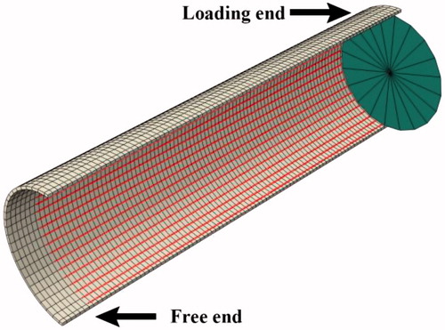
The finite element model of RACFCST specimens in the literature was established by ABAQUS, and the nonlinear spring elements of these specimens were added by the spring elements generation software for RACFCST V1.0, then the finite element model added the spring elements calculated by ABAQUS. Taking specimen named RCST2 as an example to illustrate the advantages of the spring elements generation software V1.0 and the reliability of the added nonlinear spring element, is the finite element model of RCST2.
Figure 5. Finite element model of RCST2.
When the grid size of the specimen is 5 mm, the RAC has a total of 25896 nodes, and the steel tube has a total of 9100 nodes. When the computer is configured as 8G + i5, it only takes 9 s to process all nodes of the concrete and steel tube using the spring elements generation software for RACFCST V1.0, A total of 4150 pairs of nodes were found, and the 4150 spring elements was added to the new file with suffix inp named NEWjob-1.inp, which can be submitted and calculated directly in the job module of ABAQUS. It should be emphasized that the node number of steel tube and the corresponding concrete is completely random, so it is difficult to finish this work manually in ABAQUS. However, it can be done very simply with this spring elements generation software for RACFCST V1.0 in this paper. The spring elements incorporated in the model is shown in (Red short curve). Since length of the spring element is 0, it cannot be displayed, in order to show the spring elements, the spring elements after deformation were employed in . The entire process of the addition of the nonlinear spring elements can be automatically completed with only three inputs by the spring elements generation software for RACFCST V1.0.
Figure 6. the spring elements (red short lines) of the RCST2.
The spring elements generation software for RACFCST V1.0 not only solves the problem that the nonlinear spring elements are difficult to add, but also greatly improves the working efficiency, the complex process of adding the nonlinear spring elements can be seen from the addition process of the nonlinear spring elements of the RCST2 specimen. If nonlinear spring elements are added to the joints or structures considering the bond-slip, the great difficulty can be imagined. Therefore, it is necessary to add the nonlinear spring elements by the software developed in this paper to consider the bond-slip behavior of RACFCST.
3.1.2. Development of parametric modelling software
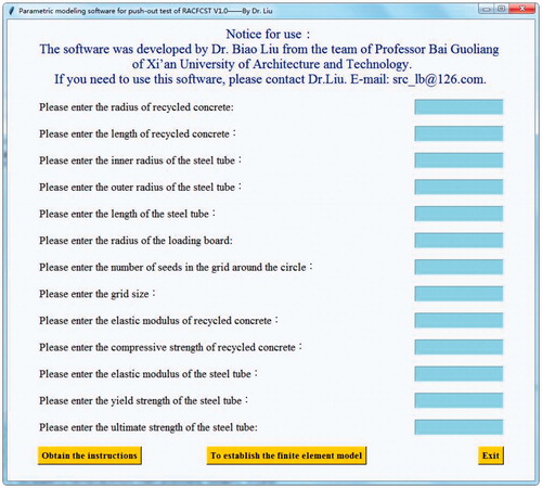
When the test specimens of RCST3- RCST15 are modeled, it is found that these specimens only changed the dimensions of the steel tube and RAC, the position of the constraint, the size of mesh, the elastic modulus and strength of the steel tube and RAC. In order to simplify the modeling process and avoid cumbersome and repeated operations on the GUI of ABAQUS, the author compiled the model script of the push-out test of RACFCST based on the model file recorded in the RCST2 modeling process by Python language, and set several key parameters as variables. At the same time, parametric modeling software for push-out test of RACFCST V1.0 was development to modify the parameters in the script. The user interface is shown in . The software can be used to directly modify the script to generate a new script, and then the script be modified can be imported into ABAQUS to quickly establish a finite element model for the push-out test.
Figure 7. Parametric modeling software for push-out test of RACFCST V1.0.
Only two steps are required to use this software as follow:
Put script of push-out test for RACFCST and parametric modeling software for push-out test of RACFCST V1.0 in the same folder;
Run the software and enter the parameters in order according to the prompts on the interface as follow:
Enter the name of the script;
Enter the radius and length of the core recycled concrete;
Enter the inner radius, the outer radius and length of the steel tube;
Enter the radius of the loading board;
Enter the number of meshes around the steel tube and the concrete;
Enter the mesh size;
Enter the elastic modulus of the steel tube and the concrete;
Enter the strength.
Click on the button – ‘To establish the finite element model’.
The all work of building the finite element model will be efficiently and accurately completed by the parametric modeling software after click on the button – ‘To establish the finite element model’, but all the work should be done in GUI of ABAQUS with extremely low efficiency before the software was developed before using this software. After the parameter input is determined, the modeling of a test specimen can be instantaneously completed, and the model is stored in the new script file, which greatly shortens the time for modeling on the GUI of ABAQUS and improves the efficiency of modifying the model. The user only needs to put the modified script file in the directory of the model and select the button named run script of file menu in the GUI of ABAQUS, and the model completed can be immediately seen in the GUI of ABAQUS after clicking the button named run script, The process of running the script in less than 1 s completes all the manual modeling that should have taken dozens of minutes on the GUI of ABAQUS.
After model was established with parametric modeling software, the spring element generation software for RACFCST V1.0 can be used to generate a new file with suffix inp, and then the file can be submitted to perform finite element analysis of the RACFCST considering bond-slip performance. The combination of parametric modeling software and spring elements generation software make the FEA process of the push-out test simpler and more efficient.
3.2. Material properties
3.2.1. RAC
The mesh size of the FEM is set to 5 mm, and the C3D8R solid element is used to the RAC. The elastic modulus of the RAC is 33,500 MPa and the Poisson's ratio is 0.3. The non-linear behavior of RAC can be captured using Concrete Damage Model in ABAQUS, and the constitutive equation proposed by Xiao jianzhuang [Citation61] is adopted in this paper.
The stressed stress-strain curve of concrete is determined by the following formula:
(3)
(3)
(4)
(4)
(5)
(5)
(6)
(6)
(7)
(7)
where, a is the parameter of the rising phase of the uniaxial compressive stress-strain curve of RAC; b is the parameter of the falling phase; fc is the compressive strength of RAC; ε0 is the peak value of the compressive strain of the RAC.
The tensile stress-strain curve of concrete is determined by the following formula:
(8)
(8)
(9)
(9)
(10)
(10)
where,
is he parameter value of the declining stage of the uniaxial tensile stress-strain curve of the concrete;
is the tensile strength of RAC;
is the peak tensile strain of the concrete corresponding to the representative value of the uniaxial tensile strength;
(3) The damage factor is calculated according to the following formula:
The damage factor of compression:
(11)
(11)
The damage factor of tension:
(12)
(12)
where, dc is the compressive damage factor and dt is the tensile damage factor. And bc = 0.7 and bt = 0.1 [Citation62].
3.2.2. Steel tube
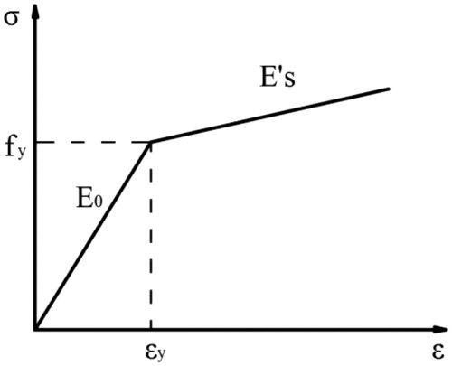
Since the wall thickness of the steel tube is 4 mm and the mesh size is 5 mm, the C3D8R solid element is also selected to the steel tube. The steel tube is assumed to behave as elasto-plastic material with hardening (i.e. bilinear stress–strain curve) both in tension and compression, as shown in . The modulus of elasticity is 200,000 MPa, the Poisson's ratio is 0.3, the yield strength is 345.9 MPa, and the ultimate strength is 455.6 MPa.
Figure 8. Constitutive model of steel tube.
4. Result and validation of FEA
The P-S curve, stress and strain obtained by finite element analysis are in good agreement with the experimental results, which proves that the proposed method for considering bond-slip behavior is reliable.
4.1. P-S curve
The P-S curve of free end and loading end measured by the test and the P-S curve calculated by ABAQUS for RCST2 are compared in this paper, as shown in .
Figure 9. The comparison of P-S of Free and Loading end calculated by FEA and Test.
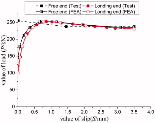
It can be seen from that the FEM established by the software developed in this paper can well simulate the relationship between force and slip during the bond-slip process. It also illustrates the feasibility of the nonlinear spring element in simulating the bond-slip performance. It can be seen from that the slip of loading end is early than free end, and this conclusion is consistent with experimental phenomena.
4.2. Cloud diagram of stress
The stress cloud diagram of the RAC and the steel tube is shown in and .
Figure 10. Stress diagram of concrete and spring elements.
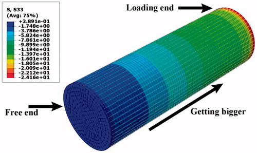
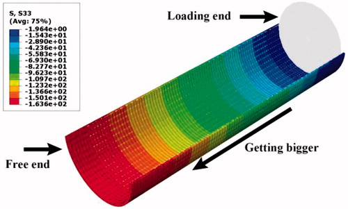
Figure 11. Stress diagram of steel tube and spring elements.
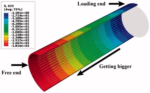
The 4150 longitudinal tangential nonlinear spring elements (white short curve in the cloud diagram) added on the surface of the concrete and the steel tube can be seen in and . Moreover, the longitudinal stress of the inner core RAC gradually decreases from the loading end to the free end. The reason is that the concrete at the loading end is close to the loading plate, and the stress is generated by the load of the loading plate and the bonding stress. However, the concrete stress at the free end is almost only caused by the bond stress. It can also be considered that the stress is caused by the deformation of the spring elements, so the stress at the free end of the concrete is relatively small; the longitudinal stress of the steel tube gradually increases from the loading end to the free end. The reason is that the stress at the loading end is completely caused by the bonding stress and can also be considered to be caused by the deformation of the spring elements. However, a section of steel tube near the free end has been balancing the applied load, this is in line with the basic mechanics theory and is consistent with the relevant test results [Citation26], and the stress of the steel tube near the support (the free end) can be calculated according to formula (3), and the calculation result of Equationequation (13)(13)
(13) is consistent with the finite element calculation result of 181 MPa.
(13)
(13)
In the formula (1): σ is the stress of steel tube, P is the value of the load, A is the area of the cross section of a steel tube, d is the inner radius of the steel tube, t is the thickness of steel tube.
It is found that the bonding stress in the surface of the RAC occurs only at the loading end through the finite element calculation in the initial loading stage, and it can also be considered that only the spring elements near the loading end is stressed. As the load increases, the stress on the surface of the RAC develops toward the free end and gradually increases. In the initial loading stage, the longitudinal stress on the surface of the steel tube is small and the interface does not start to slip, but the stress at each point on the surface of the steel tube increases gradually with the load. This indicates that the increased load acting on the RAC is transferred to the steel tube by the bonding stress. Moreover, the stress of the steel tube at the loading end is also gradually increased, but since the stress at the loading end is completely caused by the bonding stress, it is almost close to zero in the whole process of push-out test. When the maximum of the bonding stress exceeds the initial bond strength, the interface of the test specimen begins to slip, which also indicates that the nonlinear spring elements begin to deform, it can be seen that the spring elements are gradually elongated in the GUI of the ABAQUS, and the process in which the spring elements are elongated is the process of development of slip.
4.3. Distribution of strain in the length direction
In order to further compare the change of the bonding stress between the steel tube and the RAC at the interface along the loading direction (longitudinal tangential direction), so it is necessary to select a group of nodes along the loading direction at the interface of steel tube or RAC for analysis. However, due to the dense nodes, small mesh and difficult operation when selecting nodes in the GUI of ABAQUS, so it is more difficult if the nodes are inside of RAC or steel tube. To this end, the node selection program for RACFCST V1.0 was developed by the Python language, which can be used for flexible and efficient selection of nodes on steel tube or RAC in the post-processing stage. The user interface of the software is shown in .
Figure 12. Nodes selection program for RACFCST V1.0.
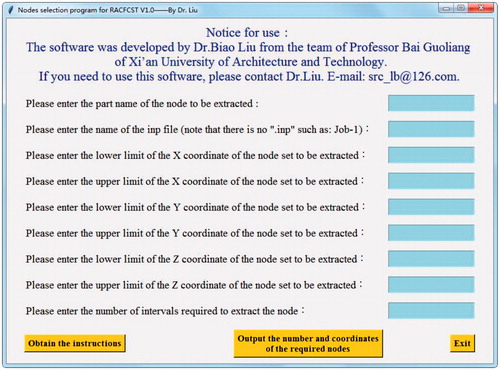
The method of use of this program is divided into two steps:
Put the model’s file with suffix inp and the nodes selection program in the same folder;
Enter the parameters in the user interface according to the prompts as follow:
Enter the upper and lower limits of the X, Y, and Z coordinates of the nodes to be selected;
Enter the number of intervals for the nodes which you need, so that you can freely select a number of nodes with appropriate and uniform distribution.
Click on the button –‘Output the number and coordinates of the required nodes’.
After clicking on the button, the software will immediately process the file with suffix inp, and store the nodes’ number and nodes’ coordinates in the text in the format required by ABAQUS. The user only needs to copy the number output by the program directly into ABAQUS to select the desired nodes, and at the same time, determine the position of the nodes according to the corresponding coordinates. This program makes the node selection in post-processing have the advantages of fast, accurate and flexible, which greatly improves the work efficiency and reduces the workload of the researcher. Taking the test specimen RCST2 and RCST5 as example, when the upper and lower limits of the X and Y coordinates are equal, the lower limit of the Z coordinate is the coordinate of the loading end, the upper limit of the Z coordinate is coordinate of the free end, and the interval of the selected nodes is 3, the nodes’ set of contact surface of steel tube selected by the nodes selection program for RACFCST V1.0 are shown in (red nodes in the picture). If the number of nodes to be selected is larger or the node is inside the component of RACFCST, the software will show greater advantages.
Figure 13. Steel nodes selected by nodes selection program.
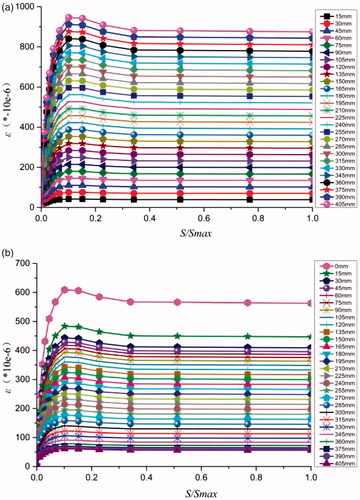
The strain at different loading moments of the nodes at different distances from the loading end of RCST2 at the interface of the steel tube and RAC are plotted, as shown in .
Figure 14. The variation of nodal strain with slip values at different distances from the loading end of RCST2. (a) The steel tube of RCST2. (b). The RAC of RCST2.
The strain at different loading moments of the nodes at different distances from the loading end of RCST5 at the interface of the steel tube and RAC are plotted, as shown in and .
Figure 15. The variation of nodal strain with slip values at different distances from the loading end of RCST5. (a) The steel tube of RCST5. (b) The RAC of RCST5.
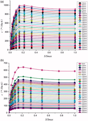
It can be seen from and that the strain at the surface of the steel tube increases as the distance from the loading end increases. It can be seen from and Figure15b that the strain at the surface of the RAC decreases as the distance from the loading end increases. And the stain of both parts increases with the increase of the load and decrease with the decrease of the load. The adhesion force of the section steel and recycle aggregate concrete at the contact surface consists of friction, bite force and chemical adhesion force before the horizontal residual section. The adhesion force consists of friction and bite force after the chemical adhesion force disappears on the horizontal participation segment.
Since the data of the RCST2 strain is not given in the test of the literature [Citation26], therefore, taking RCST5 as an example, the strain measured by the test at different positions from the loading end is compared with the strain calculated by FEA, as shown in .
Figure 16. Comparison between the strain measured by the test and the strain calculated by the FEA at different positions from the loading end with the increase of the slip value.
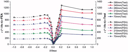
It can be seen from that the strain measured by the test and the strain predicted by the FEA are different by 200-300*10−6, This error may be due to experimental error or FEA error, and the strain error of 300*10−6 is acceptable. It can also be seen from that the strain increases as the distance from the loading end increases. The comparison shows that the FEA and the test results are consistent. The results show that the bond-slip between steel tube and RAC can be accurately simulated by the FE method presented in this paper. The above calculation results are consistent with the results of push-out test in [Citation26].
The following three points can be known through the above analysis:
The FEM considering bond-slip behavior can be efficiently and accurately established by spring elements generation software for RACFCST V1.0;
The push-out test of RACFCST can be accurately simulated by the model established by the software, and it can also be used for the simulation of bond-slip performance.
The above analysis not only illustrated the superiority of the nodes selection program in the post-processing process, but also further proved the reliability of the spring element generation software for RACFCST V1.0 in simulating the characteristic of bond-slip.
4.4. Validation of parametric modelling software
Firstly, the test specimens of RCST3-RCST15 are modeled by Parametric modeling software for push-out test of RACFCST V1.0. Secondly, the file with suffix inp of the model of each specimen is generated in ABAQUS. Finally, using the spring element generation software for RACFCST V1.0 to add the spring elements to the file with suffix inp and submit it to ABAQUS for simulation of the push-out test. The results of FEA of other specimens are compared with the results of push-out test, and the conclusions are exactly same as RCST2. Therefore, taking specimen named RCST3 as an example to illustrate the advantage and the reliability of parametric modeling software for push-out test of RACFCST V1.0.
The FEM of RCST3 was established by the parametric modeling software for push-out test of RACFCST V1.0 is shown in , comparing of the P-S curve of RCST3 was calculated by ABAQUS and measured through push-out test is shown in , The stress diagram of RAC and the steel tube was shown in and , and the spring elements deformed by force is visible on the interface of RAC and steel tube (White short curve). These results are same as RCST2 and compatible with the results of push-out test.
Figure 17. The finite model of RCST3.
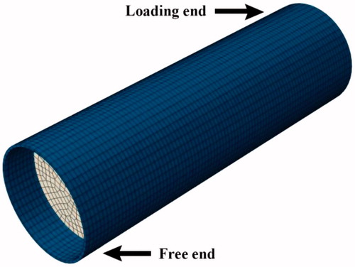
Figure 18. Comparing of the P-S curve by FEA and test.
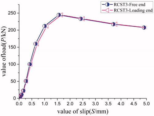
Figure 19. Stress diagram of RAC and spring elements.
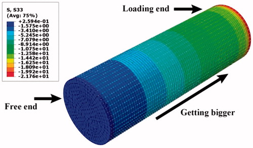
Figure 20. Stress diagram of steel tube and spring elements.
The calculations are sufficient to demonstrate the reliability, efficiency, and accuracy of the three pieces of software developed by the author. The three pieces of software developed in this paper can be used directly for FEA of RACFCST beams and columns considering bond-slip performance.
5. Conclusions
In order to solve the problem of finite element simulation of the bond-slip performance for RACFCST structure, three pieces of auxiliary software for ABAQUS were developed by using Python language. By comparing with the existing test results, the following conclusions were obtained:
The reliability of the spring element to simulate the bond-slip performance of RACFCST is verified by comparing the results of FEA with test.
Spring elements generation software for RACFCST V1.0 can efficiently, accurately and simply add spring elements according to the format and position requirements of the file suffix inp, which solves the problem of manual modeling of finite element considering bond-slip performance;
The finite element model established by the RACFCST spring elements generation software V1.0 can accurately simulate the RACFCST bond-slip performance;
The nodes selection for RACFCST procedure makes the work of nodes selection flexible and efficient in the post-processing process;
Parametric modeling software for push-out test of RACFCST V1.0 can easily generate model scripts, and import ABAQUS to directly establish finite element model, this software makes the RACFCST modeling process efficient and accurate.
The research method in this paper can be directly applied to CFST or RACFCST structures, and can also help researchers of composite structures to conduct finite element analysis considering the bond slip performance. In the next step, it is also necessary to conduct a parametric study on the bond-slip properties of RACFCST. Parametric study on the bond-slip properties of RACFCST will be carried out in future research work. Factors that should be considered in the parametric study include: replacement rate of RAC, the ratio of the internal concrete length to the inner diameter of the steel tube, the amount of expansion agent, the roughness inside the steel tube, the anchoring device inside the steel tube and the conditions of the boundary conditions, etc. And some of the parameters in these parameters need to be determined according to the test, such as the effect of the amount of expansion agent on the bond-slip performance. In addition, there is a need to explore methods for simulating the effects of bulking agents in finite element software such as ABAQUS. After solving these key issues, Parametric studies of the bond slip properties of RACFCST will be conducted.
Additional information
Funding
References
- Guo H, Shi C, Guan X, et al. Durability of recycled aggregate concrete – a review. Cement Concrete Composites. 2018;89:251–259.
- Dimitriou G, Savva P, Petrou MF. Enhancing mechanical and durability properties of recycled aggregate concrete. Constr Build Mater. 2018;158:228–235.
- Silva RV, de Brito J, Dhir RK. Fresh-state performance of recycled aggregate concrete: a review. Constr Build Mater. 2018;178:19–31.
- Bui NK, Satomi T, Takahashi H. Mechanical properties of concrete containing 100% treated coarse recycled concrete aggregate. Constr Build Mater. 2018;163:496–507.
- Mcginnis MJ, Davis M, de la Rosa A, et al. Strength and stiffness of concrete with recycled concrete aggregates. Constr Build Mater. 2017;154:258–269.
- Chakradhara Rao M. Properties of recycled aggregate and recycled aggregate concrete: effect of parent concrete. Asian J Civ Eng. 2018;19:103–110.
- Lye C, Dhir RK, Ghataora GS. Shrinkage of recycled aggregate concrete. Proc Inst Civil Eng Struct Build. 2016; 169:867–891.
- Bairagi NK, Vidyadhara HS, Ravande K. Mix design procedure for recycled aggregate concrete. Constr Build Mater. 1990;4:188–193.
- Thomas J, Thaickavil NN, Wilson PM. Strength and durability of concrete containing recycled concrete aggregates. J Build Eng. 2018; 19:349–365.
- Rahal K. Mechanical properties of concrete with recycled coarse aggregate. Build Environ. 2007;42:407–415.
- Ho NY, Lee YPK, Lim WF, et al. Efficient utilization of recycled concrete aggregate in structural concrete. J Mater Civ Eng. 2013;25:318–327.
- Chen Y, Feng R, Shao Y, et al. Bond-slip behaviour of concrete-filled stainless steel circular hollow section tubes. J Const Steel Res. 2017;130:248–263.
- Schneider SP. Axially loaded concrete-filled steel tubes. J Struct Eng. 1998;124:1125–1138.
- O’Shea MD, Bridge RQ. Design of circular thin-walled concrete filled steel tubes. J Struct Eng. 2000;126:1295–1303.
- Lam D, Gardner L. Structural design of stainless steel concrete filled columns. J Const Steel Res. 2008;64:1275–1282.
- Liang QQ, Fragomeni S. Nonlinear analysis of circular concrete-filled steel tubular short columns under axial loading. J Const Steel Res. 2009;65:2186–2196.
- Patel VI, Liang QQ, Hadi M. Nonlinear analysis of biaxially loaded rectangular concrete-filled stainless steel tubular slender beam-columns. Eng Struct. 2017;140:120–133.
- Mirmomeni M, Heidarpour A, Zhao X, et al. Size-dependency of concrete-filled steel tubes subject to impact loading. Int J Impact Eng. 2017;100:90–101.
- Chen J, Wang Y, Roeder CW, et al. Behavior of normal-strength recycled aggregate concrete filled steel tubes under combined loading. Eng Struct. 2017;130:23–40.
- Tao Z, Song T, Uy B, et al. Bond behavior in concrete-filled steel tubes. J Const Steel Res. 2016;120:81–93.
- Chen ZP, Xu JJ, Xue JY, et al. Push-out test on the interface bond-slip behavior and calculation on bond strength between steel tube and recycled aggregate concrete in RACFST structures. China Civil Eng J. 2013;46:49–58.
- Yan C, Wang ZB, Liu F. Experimental research on the bond-slip behaviour of recycled aggregate concrete-filled square steel tubes. Jiangsu Const. 2013;4:97–99.
- Li WN, Xu JJ, Chen ZP, et al. Experimental research on the bond-slip behavior of recycled aggregate concrete-filled square steel tubes. J Guangxi Univ (Natural Science Edition). 2012;37:68–74.
- Chen Z, Xu J, Li W, et al. Influence of recycled coarse aggregate content on bond strength and invalidation mechanism between steel tube and recycled aggregate concrete. Eng Mech. 2014;31:70–78.
- Zuo G, Wang ZB, Qiao Y. Experimental study on bond-slip performance of micro expansion recycled concrete. Concrete Cement Prod. 2015;2:5–9.
- Zhang WD, Wang ZB, Sun WB, et al. Experimental research on the interface bond-slip behavior of recycled aggregate concrete-filled square steel tube. Build Struct. 2015;45:64–68.
- Xu JJ, Chen ZP, Xue JY, et al. Failure mechanism of interface bond behavior between circular steel tube and recycled aggregate concrete by push-out test. J Build Struct. 2013;34:148–157.
- Zhao Q. Experimental study on bonding properties of square steel tube recycled concrete. J Huaqiao Univ (Nat Sci). 2016;37:115–119.
- Wang J, Huang WP, Zuo JP, et al. Rheological perturbation effect of rock and combined support of concrete filled steel tubes in deep coal mine roadway. Chinese J Rock Mech Eng. 2018;37:461–472.
- Zhang R. Experimental study on seismic behavior of square steel tube recycled concrete columns. Hefei Univ Technol. 2014;1–54.
- Mao J. Study on seismic behavior of steel tubular steel recycled concrete frame-concrete core tube structure. Guangzhou Univ. 2017;1–79.
- Genikomsou AS, Polak MA. 3D finite element investigation of the compressive membrane action effect in reinforced concrete flat slabs. Eng Struct. 2017;136:233–244.
- Genikomsou AS, Polak MA. Finite element analysis of punching shear of concrete slabs using damaged plasticity model in ABAQUS. Engi Struct. 2015;98:38–48.
- Jawdhari A, Harik I. Finite element analysis of RC beams strengthened in flexure with CFRP rod panels. Constr Build Mater. 2018;163:751–766.
- Othman H, Marzouk H. Finite-element analysis of reinforced concrete plates subjected to repeated impact loads. J Struct Eng. 2017; 143:4017120.
- Mohamed K, Farghaly AS, Benmokrane B, et al. Nonlinear finite-element analysis for the behavior prediction and strut efficiency factor of GFRP-reinforced concrete deep beams. Eng Struct. 2017;137:145–161.
- Abu-Obeidah A, Hawileh RA, Abdalla JA. Finite element analysis of strengthened RC beams in shear with aluminum plates. Comput Struct. 2015;147:36–46.
- Hawileh R, Abdalla J, Tanarslan M, et al. Modeling of nonlinear cyclic response of shear-deficient RC T-beams strengthened with side bonded CFRP fabric strips. Comput Concrete. 2011;8:193–206.
- Hawileh RA, Naser M, Zaidan W, et al. Modeling of insulated CFRP-strengthened reinforced concrete T-beam exposed to fire. Eng Struct. 2009;31:3072–3079.
- Hawileh RA, Rahman A, Tabatabai H. Nonlinear finite element analysis and modeling of a precast hybrid beam–column connection subjected to cyclic loads. Appl Math Model. 2010;34:2562–2583.
- Rasheed HA, Larson KH, Amiri SN. Analytical solution of interface shear stresses in externally bonded FRP-strengthened concrete beams. J Eng Mech. 2013;139:18–28.
- Hawileh RA. Finite element modeling of reinforced concrete beams with a hybrid combination of steel and aramid reinforcement. Materials Des. 2015;65:831–839.
- Hawileh RA, Naser MZ, Abdalla JA. Finite element simulation of reinforced concrete beams externally strengthened with short-length CFRP plates. Composites B Eng. 2013;45:1722–1730.
- Sakar G, Hawileh RA, Naser MZ, et al. Nonlinear behavior of shear deficient RC beams strengthened with near surface mounted glass fiber reinforcement under cyclic loading. Mater Des. 2014;61:16–25.
- Hawileh RA. Nonlinear finite element modeling of RC beams strengthened with NSM FRP rods. Constr Build Mater. 2012;27:461–471.
- Al-Saoudi A, Al-Mahaidi R, Kalfat R, et al. Finite element investigation of the fatigue performance of FRP laminates bonded to concrete. Composite Struct. 2019;208:322–337.
- Kalfat R, Al-Mahaidi R. Finite element investigation into the size effect of bidirectional fibre patch anchors used to enhance the performance of FRP-to-concrete joints. Composite Struct. 2015;121:27–36.
- Sun XL, Hao JP, Xue QP, et al. Experimental study on seismic behavior of walled concrete-filled steel tubular columns. J Build Struct. 2018;39:92–101.
- Wang XT, Zhou XH, Wang DS, et al. Research on horizontal load bearing capacity of concrete-filled square steel tubular frame-thin steel plate shear walls structure with cross stiffeners. J Build Struct. 2017;38:1–9.
- Qian Y, Li W, Han L, et al. Behaviour of concrete-encased concrete-filled steel tubular column to steel beam joints under cyclic loading. China Civil Eng J. 2017;50:27–38.
- Zhang YZ. Finite element analysis on seismic behavior of GFRT columns with load-transfer details. J Build Struct. 2018;39:20–28.
- Ouyang Y, Kwan AKH. Finite element analysis of square concrete-filled steel tube (CFST) columns under axial compressive load. Eng Struct. 2018;156:443–459.
- Ai TT, Liu JM, Song CC, et al. Study on ABAQUS simulation method for pure torsion structure of box type SRC in consideration with bond and slip. Eng Constr. 2016;48:14–19.
- Su X, Yang Z, Liu G. Finite element modelling of complex 3D static and dynamic crack propagation by embedding cohesive elements in abaqus. Acta Mechanica Solida Sinica. 2010;3:271–282.
- Chi JJ. Experimental study and finite element analysis of shear-bonding properties of CFST joints. Changsha Univ Sci Technol. 2004;1–73.
- Cao C, Lu YW, Liang HJ, et al. Nonlinear finite element analysis of bond behavior between steel and concrete of self-stressing concrete filled steel tube. J Wuhan Univ (Eng Sci). 2015;48:202–206.
- Liu YL, Ye XG, Shi X, et al. Comparative studies and numerical analysis of the bond-slip curves of reinforced concrete. Ind Constr. 2015;45:66–69.
- Qin L, Yin ZQ, Pan HY. Finite element analysis of bond-slip behavior of beam column joints with high strength steel. J Northeast Electric Power Univ. 2018;38:64–70.
- Li M, Cai J, Chen FS. Numerical study on the dynamic bond behavior of reinforced concrete. Shanxi Archit. 2016;42:20–22.
- Li HW, Wang WD. Application of ABAQUS secondary development in finite element analysis of concrete-filled steel tubular structures. J Build Struct. 2013;34:353–358.
- Xiao JZ. Recycled concrete. Beijing: China Architecture & Building Press; 2008.
- Birtel V, Mark P. Parameterised finite element modelling of RC beam shear failure. ABAQUS Users’ Conference; 2006. p. 95–108.