
ABSTRACT
Tools for image-based 3D-reconstruction are commonly used for cultural heritage applications; however, wider usage has increased variability in the quality of output 3D models. Geometric variations between 3D models acquired with differing methods make metric conservation applications such as condition monitoring and measuring change over time challenging. This article presents an investigation of wavelength selection using a modified off-the-shelf DSLR camera and bandpass filters to improve input image quality in a 3D-reconstruction study of a wooden sculpture of a coyote and turtle from the Smithsonian American Art Museum. The sculpture has a large crack of concern to conservators, but its curved, dark shiny surface challenges image-based dimensional monitoring. Selecting infrared wavelengths rather than the visible light for 3D reconstruction input images reduced specular surface reflections and improved image contrast resulting in improved recording of the 3D shape. 3D-reconstructions using infrared radiation produce better reconstructions than those using visible light. In this case reconstructed surface discrepancies between visible light are ∼0.6 mm whilst those using infrared are ∼0.3 mm. Results suggest that reflected infrared images are more forgiving and flexible for recording 3D data over time for dark, shiny wooden surfaces and thus improve the reliability and comparability of image-based 3D-reconstruction.
RÉSUMÉ
Les outils pour la reconstruction en 3D à partir d'images sont souvent employés dans le domaine du patrimoine culturel ; cependant, un recours plus généralisé à ce type de techniques est à l'origine d'une variabilité croissante de la qualité des modèles 3D. L'emploi de différentes méthodes génère des variations géométriques entre les modèles 3D obtenus, ce qui complique la quantification appliquée à des problématiques de restauration telles que, par exemple, suivre l'état de conservation et mesurer les changements qui s'opèrent au cours du temps. Cet article présente une étude relative à la sélection de la longueur d'onde, à partir d'un appareil photographique réflexe numérique standard dont les paramètres ont été modifiés et de filtres passe-bande, pour améliorer la qualité des images servant de base à la reconstruction 3D d'une sculpture du Smithsonian American Art Museum. La sculpture en bois, qui représente un coyote et une tortue, présente une large fissure, source d'inquiétude pour les restaurateurs. Cependant, sa surface incurvée, sombre et brillante rend très difficile le suivi de l'évolution dimensionnelle de l'objet à partir d'images. L'acquisition des données dans des longueurs d'onde du domaine infrarouge, plutôt que dans le domaine visible, réduit la réflexion spéculaire de surface et améliore le contraste des images, ce qui conduit à un meilleur enregistrement de la forme en 3D. Les reconstructions en 3D utilisant les radiations infrarouges produisent de meilleures reconstructions que celles utilisant la lumière visible. Dans notre cas d'étude, les écarts de mesure de la surface reconstruite sont de ∼0,6 mm en utilisant le domaine visible, tandis qu'ils sont de ∼0,3 mm en employant le domaine infrarouge. Les résultats suggèrent que les images acquises par réflexion dans le domaine infrarouge offrent plus de marge de manœuvre et de flexibilité pour l'acquisition des données 3D au cours du temps pour des surfaces en bois sombres et brillantes, et améliorent ainsi la fiabilité et la possibilité de comparer les reconstructions 3D à partir d'images. Traduit par Johanna Salvant.
RESUMO
Ferramentas para reconstrução digital 3D baseada em imagem são comumente utilizadas para aplicações no patrimônio cultural, entretanto, a ampla aplicação aumentou a variabilidade na qualidade de saída de modelos 3D. As variações geométricas entre modelos 3D resultantes de métodos diferentes tornam as aplicações métricas de conservação, como monitoramento de condições e medição de mudanças ao longo do tempo, um desafio. Este artigo apresenta uma pesquisa da seleção de comprimento de onda usando uma câmera DSLR e filtros “bandpass” para melhorar a qualidade da imagem de entrada em um estudo de reconstrução 3D de uma escultura de madeira de um coiote e uma tartaruga pertencente ao Smithsonian American Art Museum. A escultura tem uma fissura grande que preocupa os conservadores, mas a sua superfície curva, escura e brilhante desafia o monitoramento dimensional baseado em imagem. Selecionar comprimentos de onda de infravermelho em vez da luz visível para imagens de entrada de reconstrução 3D reduziu os reflexos da superfície especular e melhorou o contraste da imagem, resultando na gravação de forma aprimorada em 3D. As reconstruções 3D com a utilização de radiação infravermelha produzem reconstruções melhores das realizadas usando luz visível. Neste caso, as discrepâncias de superfícies reconstruídas entre luz visível são de ∼0.6 mm, enquanto as que usam infravermelho são de ∼0.3 mm. Os resultados sugerem que imagens de infravermelho refletidas são mais tolerantes e flexíveis para registrar dados 3D ao longo do tempo para superfícies de madeira escuras e brilhantes e, assim, melhorar a confiabilidade e comparabilidade da reconstrução 3D baseada em imagem. Traduzido por Sandra Baruki.
RESUMEN
Las herramientas de reconstrucción 3D a partir de imágenes se usan comúnmente en la conservación del patrimonio cultural; sin embargo, el incremento en el uso de este recurso ha aumentado también las variantes en la calidad de los productos 3D obtenidos. Las variaciones geométricas entre los modelos 3D adquiridos con diferentes métodos, hacen que las aplicaciones de conservación de medición tales como monitoreo del estado de conservación y medición de los cambios a través del tiempo, sean un reto. Este artículo presenta una investigación sobre la selección de la longitud de onda utilizando una cámara DSLR comúnmente disponible en el mercado, modificada y filtros de paso de banda para mejorar la calidad de la imagen obtenida en el estudio de reconstrucción 3D de una escultura de madera de un coyote y una tortuga del Smithsonian American Art Museum. La escultura presenta una gran grieta que preocupa a los conservadores, pero su superficie curvada, oscura y brillante es un reto para el seguimiento dimensional basado en imágenes. La selección de longitudes de onda infrarrojas en lugar de la luz visible para las imágenes de entrada de la reconstrucción 3D, redujo los reflejos especulares de la superficie y mejoró el contraste de la imagen, lo que dio lugar a un mejor registro en 3D. Las reconstrucciones 3D que utilizan la radiación infrarroja producen mejores resultados que las que utilizan la luz visible. En este caso, las discrepancias de la superficie reconstruida entre la luz visible son ∼0,6 mm, mientras que las que utilizan infrarrojos son ∼0,3 mm. Los resultados sugieren que las imágenes infrarrojas reflejadas son más adaptables y flexibles para el registro de datos 3D del paso del tiempo para superficies de madera oscuras y brillantes y, por tanto, mejoran la fiabilidad y la comparabilidad de la reconstrucción 3D basada en imágenes. Traducción: Mirasol Estrada; revisión: Irene Delaveris y Amparo Rueda.
1. Introduction
Accessible consumer imaging systems, both consumer digital cameras and automated 3D reconstruction software solutions, make it increasingly easy to capture image sets and process 3D reconstructions by heritage professionals. Image-based 3D reconstruction techniques have become popular and more accessible, in terms of cost and complexity, for cultural heritage documentation as a result of the availability of a variety of low-cost and open source software systems, in addition to high-quality, high-resolution consumer digital cameras (Remondino et al. Citation2014). The available software for image-based 3D reconstruction have increased automation and do not require an expert user in addition to the equipment required being flexible and minimal, all factors that contribute to the popularity and accessibility of the methods. These image-based 3D reconstruction techniques are considered accessible, portable, and flexible producing high-resolution results to non-expert users, and therefore, these techniques have been widely adopted for 3D recording of heritage. A couple of comprehensive and available reviews for image-based reconstruction include Remondino and El-Hakim (Citation2006) and Remondino (Citation2011). Image-based reconstruction techniques have been used for a range of heritage applications including specific applications for conservation and monitoring (Robson et al. Citation2004; Remondino et al. Citation2011; Dellepiane et al. Citation2013; Abate et al. Citation2014).
Photogrammetry is often the term used, but the image-based 3D reconstruction method widely used for cultural heritage documentation is more specifically structure from motion (SfM) paired with multiview stereo (MVS). This automated and flexible method is a computer vision approach that simultaneously and automatically determines the camera calibration and the geometry of the scene or object. It relies on the use of multiple images for the identification of correspondences for the image matching. Access to non-expert users, in terms of cost and complexity, is an important advantage of SfM-MVS methods. One example, Agisoft Metashape, formerly known as PhotoScan, provides an “end-to-end” solution that is widely used in heritage applications.
The availability, flexibility, and automation that make image-based 3D reconstruction an accessible process also increase the variability in the output models, presenting new challenges in maintaining 3D output quality and limiting potential uses for the resulting 3D models. Nearly any digital camera and lens, including mobile cameras, can be used to acquire images of scenes or objects that can range in scale, close-up or far away, with different lighting conditions. The available software tools require little knowledge and input. While a resulting 3D model may “look good” and be a fairly complete reconstruction that resembles the recorded object or scene, the use of the model will be limited if there is not information about the data (acquisition, processing, etc.) and if the quality and reliability cannot be assessed. The specific use of the 3D outputs must be defined in order to understand whether the output images and models are fit for purpose. Conservation applications for 3D reconstruction, including monitoring condition and measuring change over time, require scientific rigor to establish reliable and accurate models. For these applications it is important to establish what types and levels of change can be recorded.
This research focused on image-based 3D reconstruction for accurate and reliable scientific records for conservation documentation while trying to maintain the ease of access of the imaging and 3D reconstruction workflows. Since the quality of the output reconstruction is reliant on the input image quality and the geometry of the image network, or the configuration of camera positions where images were acquired around the object, this research is directed towards scientific image acquisition specifically looking at local contrast, modified cameras, and wavelength selection and is a subsection of a larger research project (Webb Citation2020). This article presents an investigation of improving 3D reconstruction through an imaging study of a museum object where wavelength selection with a modified camera and bandpass filters is used to optimize the input image quality. The imaging study provided evidence of wavelength selection for improved 3D reconstruction and demonstrated the practical applications of the findings. Specifically, the imaging study presents the use of reflected infrared (IR) images to increase the local contrast and reduce specular surface reflections improving the geometry, or the recording of the shape of the object, and reducing the variability relating to the image network.
2. Consistent 3D model quality and optical surface properties
Consistent high-quality 3D models suited to conservation are challenging to achieve and difficult to independently validate. Output models from image-based 3D reconstruction can vary in quality depending on the skill of the user. A starting point to improve image-based 3D reconstruction includes identifying the available best practices and standards. For several years best practices and standardization have been called for in image-based 3D reconstruction to provide both advantages and limitations of systems and solutions (Remondino Citation2011), to standardize the acquisition for archaeologists (Dellepiane et al. Citation2013), to evaluate the resolution, repeatability, and reproducibility (Toschi et al. Citation2014), and to support responsible archaeological recording for precision, accuracy, and sustainability (Sapirstein and Murray Citation2017). Remondino et al. (Citation2013) provided guidelines based on a critical review of the digitization pipeline targeting the non-expert user. Historic England produced two best practice documents aiming to promote consistent quality: Metric Survey Specifications for Cultural Heritage (Andrews, Bedford, and Bryan Citation2015) and Photogrammetric Applications for Cultural Heritage: Guidance for Good Practice (Historic England Citation2017). Another aspect of improving image-based 3D reconstruction can be developing workflows. Cultural Heritage Imaging (CHI) in collaboration with the Bureau of Land Management (BLM) has developed an error minimization workflow that iteratively removes bad points and optimizes the alignment and calibration removing significant errors and producing higher quality results (Schroer, Mudge, and Lum Citation2017). These references are not exhaustive of the work to improve image-based 3D reconstruction but provide a foundation for the research presented in this article.
The quality of the output reconstruction is reliant on the geometry of the image network and the input image quality. Some factors that influence the image network include the overlap of images, camera to object distance, and image coverage of the object (i.e., overall or partial). Image quality is influenced by the camera, lens, illumination, and camera-object distance, to name a few factors. Specifically, the pixel size, the lens focal length, and the camera-object distance influence the detail that can be resolved by the images and the resulting reconstruction. The ground sampling density (GSD) is the size of an object or feature in object space represented by a single pixel in the image space, and it is calculated by dividing the camera-object distance by the focal length and multiplying this by the pixel size (Andrews, Bedford, and Bryan Citation2015). Calculating the GSD can help to understand the parameters required for recording the smallest detail that needs to be resolved. In general, multiplying the GSD by at least two estimates the size of detail that can be resolved by image-based 3D reconstruction under certain parameters, providing an estimated feature accuracy. GSD provides a convenient and easily calculated metric; however, it cannot account for the exact number of pixels needed to provide a valid 3D reconstruction of local surface detail because of the variable image sampling dimensions used in the reconstruction process. Once the desired level of detail is accounted for in the selection of the imaging system, camera-object distance, and image network, there is the potential of looking at other means of improving image quality, for example, wavelength.
Materials can respond differently to different wavelengths, within or beyond visible light, and in some cases this difference can increase image contrast and clarity providing an enhanced view of features of interest, improving the image quality. Consumer digital cameras that are optimized for visible light, color photography can be modified by removing internal filters, which provides additional capabilities for imaging into the UV and IR ranges and wavelength selection. Modifications take advantage of the fact that the sensor at the heart of consumer digital cameras are inherently sensitive from the near UV to near infrared (NIR), while maintaining a reasonably inexpensive, user friendly, portable, and high-resolution imaging device. Webb et al. (Citation2018) includes a longer description of modified cameras available. Two of these modifications are a full-spectrum conversion that removes the IR blocking filter and a monochrome conversion that removes the color filter array (the RGB filters on the pixels used to reconstruct a color image) in addition to the IR blocking filter. A full-spectrum conversion allows for color, visible light images to be acquired by using specific filter(s) on the lens, and this conversion is more widely used for multiband conservation documentation. A monochrome camera has more potential for multispectral imaging and benefits from increased amounts of light per pixel across the full spectrum improving the camera’s signal-to-noise and removing bias when particular wavelengths of light are to be detected. However, the monochrome conversion has higher risk for damaging the camera and is a more expensive process. While modified cameras are being used for 2D conservation documentation, this article presents a unique workflow and application for image-based 3D reconstruction for conservation documentation.
In order to understand whether the 3D reconstruction quality has improved, there needs to be a reliable method for quality assessment. However, there is a lack of standards and guidelines for evaluating 3D data (Toschi et al. Citation2014). One method commonly used for assessing techniques is to compare the resulting model with a 3D model obtained by another higher accuracy 3D technique (Toschi et al. Citation2014). Establishing a higher accuracy reference dataset with this is not always straightforward especially for heritage documentation, and it is complicated by defining what should actually be compared and evaluated (the full object, a small area, or single points) (Remondino et al. Citation2014).
3. Imaging study
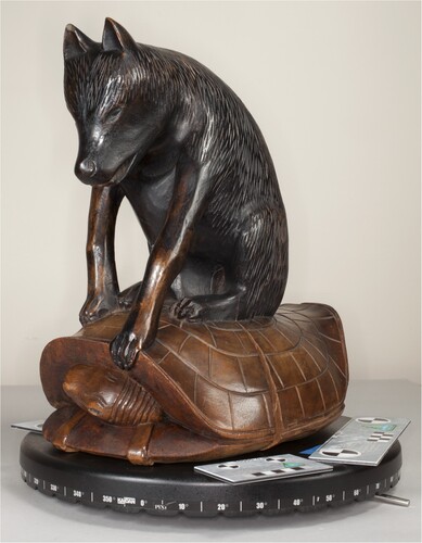
The effect of wavelength selection for improved image quality was explored through the 3D recording of a museum object, an untitled wooden sculpture of a coyote and turtle (1986.65.339), from the Smithsonian American Art Museum (SAAM) (). The object, made by an unidentified artist, is a carved, varnished, and painted walnut sculpture of a coyote sitting atop a turtle. It measures 39.2 × 24.5 × 35.5 cm and dates after 1930. The sculpture may portray a Native American (possibly Hopi) tale about Turtle turning the tables on trickster Coyote, provoking him into tossing Turtle back into his river home, after he had wandered too far from its banks to get back on his own (Untitled (Coyote and Turtle). After Citation1930). There were thought to be at least two coatings on the object including a dark stain on the coyote and a second coating on the turtle (Helen Ingalls, pers. comm., Citation2017).
Figure 1. Wooden sculpture of a coyote and turtle, Untitled (1986.65.339), 39.2 × 24.5 × 35.5 cm, part of the SAAM collections.
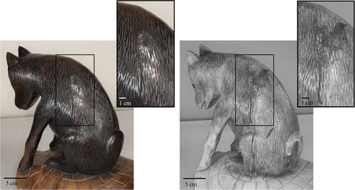
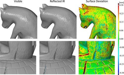
The sculpture has large cracks running along the carved back and side of the coyote and continuing through the turtle shell (). The conservation concern is that fluctuating environmental parameters (relative humidity and temperature) in the gallery were contributing to increased dimensional changes in the wood, which could lead to further cracking. Cracking has been documented by using a sheet of Mylar to trace the crack as a baseline for comparison to monitor dimensional movement over time.
Figure 2. Visible light and reflected IR images of coyote and turtle sculpture with detail views of cracking: visible light (left) and reflected IR (right). Reflected IR images increase the local contrast of the cracking and reduce the impact of the specular reflections.
3D reconstruction from images has the potential to improve the monitoring of the cracking and any dimensional change over time. The cracking is on a curved area of the three-dimensional object, making 2D documentation challenging for dimensional monitoring. In addition, the dark and shiny object presents challenges for visible light recording, either 2D or 3D. The objectives of the imaging study were to investigate whether there was a more accurate way to monitor vulnerable pieces in situ and to establish detailed baseline imagery for monitoring dimensional change. This study investigated the use of spectral and 3D imaging techniques for documenting museum collections and established a workflow for wavelength selection and spectral-3D recording. In the study, a comparison between imaging and structured light scanning of a local area of detail was made to investigate the recording potential of each technique in terms of fine detail recording.
3.1. Experimental methods
Two imaging campaigns [Acquisitions A and B] were conducted with image sets acquired for both visible light (VIS) and reflected IR image-based 3D reconstruction.
Visible light images were acquired using an unmodified Canon 5D Mark II camera with the 50 mm lens and 100 mm lens for Acquisition A and the 60 mm lens for Acquisition B (). The object was illuminated using a Canon Macro Ring Lite MR-14EX and three Canon Speedlite 580 EX II flashes with umbrellas ( for A; for B). An X-rite ColorChecker Passport was used for processing the white balance of the VIS images.
Figure 3. Imaging setup for Acquisition A that shows the object on the turntable and the positions of the lights.
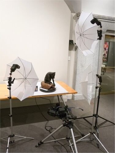
Figure 4. Imaging setup for Acquisition B in the Lunder Conservation Center that shows the position of the lights to the right of the camera.
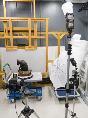
Table 1. Reference list for camera and lens information.
Reflected IR images were acquired using the modified Canon 5D Mark II with the 60 mm lens (). The modification of this camera is a monochrome conversion that included the removal of the IR blocking filter and anti-aliasing filter, the sensor cover glass, and about 5 μm of the microlenses and color filter array, which was a service provided by MaxMax LDP LLC (Dan Llewellyn, pers. comm, 2016; MaxMax.com - LDP LLC Citationn.d.). A Peca 910 filter was used on the lens to restrict the recorded radiation to the NIR region, cutting off wavelengths below about 800 nm (Peca Products Citationn.d.). Similar illumination as the VIS imaging was used for the IR images for both Acquisition A and B. For Acquisition A, it was not possible to mount the ring flash onto the 60 mm lens with the IR filter, and it was handheld in front of the lens for each exposure (which is not recommended). For Acquisition B, an adapter had been purchased and the ring light was mounted onto the lens. A Spectralon 99% Diffuse Reflectance Standard was included in an initial image as a reference for exposure.
The image-based 3D reconstruction included a turntable setup. Images were acquired of the first view by rotating the object on the turntable. The camera was then raised by increasing the height of the central tripod column to the position for the second view. The camera was not refocused, but Live View on a tethered laptop was used to ensure that the focus was still sharp and that the object was centered in the field of view. The tripod was moved to fine-tune the focus as opposed to refocusing the camera. Refocusing the camera would alter the camera calibration in the 3D reconstruction process potentially giving images which could not on their own be reliably, geometrically corrected. To avoid such subsets of imagery complicating the reconstruction the lens focus was maintained for each image set. Images included reference scales and targets for the processing, calibration, and scaling. CHI photogrammetric scale bars (5 and 18 cm bars) were placed around the object during acquisition for scaling ().
Images were acquired as RAW files (*.CR2 Canon files) and converted to JPEGs using Adobe Camera Raw (ACR). For the imaging study, JPEGs were used to process the image-based 3D reconstruction; however, there is a risk of losing information in low frequency areas due to compression, so TIFFs may be considered for future work. The image-based 3D reconstruction processing used Agisoft PhotoScan v. 1.3.3 and followed the CHI and BLM error minimisation workflow (Schroer, Mudge, and Lum Citation2017).
includes the imaging parameters for Acquisition A and B including the estimated GSD. GSD is used in this article as an indicator of the differences between the acquired image sets to better understand the links between input images and output 3D reconstruction quality.
Table 2. Imaging Parameters for Acquisition A and B.
Acquisition A recorded the full object in the round and incorporated detail images of the area of the crack for both VIS and IR. The VIS acquisition for A included seven camera views with one full rotation of the object at each view. Additional images were acquired using the 50 mm lens and the 100 mm macro lens for increased resolution of the crack details (). The IR acquisition for A included two camera views with rotations of the object at each view, and detail images were acquired using the 60 mm lens at a shorter camera-object distance (). Note that the 250 images taken for the VIS reconstruction versus the 72 images for the IR reconstruction are a function of the learning process (). The lenses, lighting, and imaging networks varied between the VIS and IR image sets complicating the assessment of whether wavelength selection could improve image-based 3D reconstruction.
Figure 5. Visualization of image network for Acquisition A VIS 3D reconstruction. Screenshot from PhotoScan.
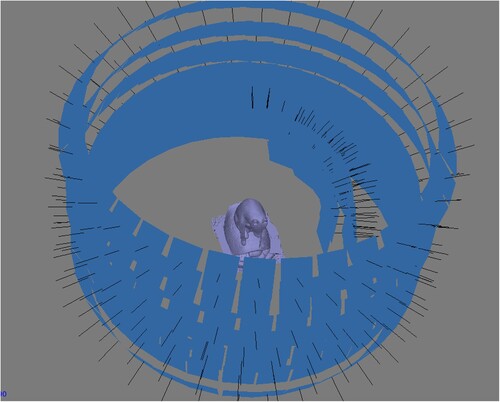
Figure 6. Visualization of image networks for Acquisition A IR 3D reconstruction. Screenshot from PhotoScan.
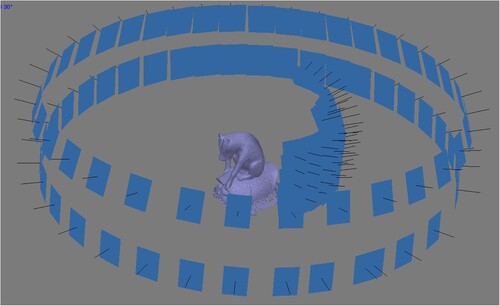
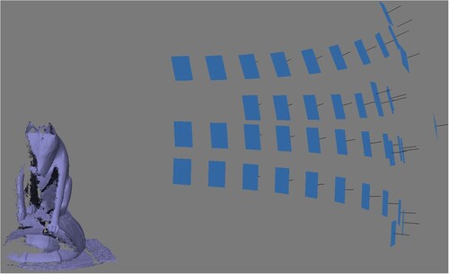
Acquisition B was conducted eight months later with the goals being adapted from knowledge gained having processed the data from Acquisition A. As a result, acquisition concentrated on increased comparability between image sets captured. This would provide a better controlled study using the two cameras and same lens. This subsequent acquisition was not intended to be a direct comparison with Acquisition A. In particular since the overall objective of the imaging was to monitor the cracking on the coyote, only the area of interest around the cracking was imaged and not the entire object in the round. For Acquisition B, the camera was positioned approximately 111 cm from the object (measured from the image plane) and the acquisition included four camera views with partial rotations of the object (only 100° rotation) at each view (). The same image network was used for the IR images as the VIS images using the camera height and degree markings on the turntable to replicate the views ().
Figure 7. Visualization of image network for Acquisition B VIS 3D reconstruction. Screenshot from PhotoScan.
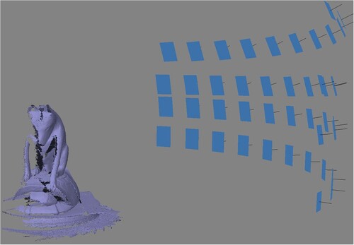
Figure 8. Visualization of image network for Acquisition B IR 3D reconstruction. Screenshot from PhotoScan.
Since there are no clear standards for assessing the accuracy of 3D reconstructed heritage surfaces (Toschi et al. Citation2014), the resulting model was compared against a 3D model obtained with an alternative technique. Only a detailed area of the sculpture that included the cracking was recorded using a structured light scanner with the aim of having a reference dataset to assess the image-based 3D reconstructions (). The object was scanned at the time of Acquisition B using the AICON3D smartSCAN-HE scanner with the S-150 field of view, a base length of 240 mm, and a working distance of 370 mm (). The scanner was calibrated following the AICON3D scanning procedure and using the AICON3D calibration plate. A manual turntable was used to rotate the object.
Figure 9. Screenshot of structured light scanned results showing the area of the object that was recorded.
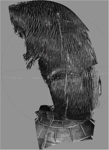
Table 3. AICON3D systems specifications for smartSCAN-HE with the S-150 lens set.
The resulting 3D reconstructions and structured light scanned data were assessed and compared using GOM Inspect software. This is a free version of a software produced by GOM, a company focusing on precise industrial metrology (https://www.gom.com/en). There are limitations with the free version; however, a benefit is that the software maintains strong support and development as part of a commercial company that supplies metrology software and hardware solutions. It is certified by PTB and NISTFootnote1 and can be used as a traceable product for quantitative analysis.
All three datasets were on their own arbitrary local coordinate systems and needed to be aligned using a prealignment function, a global best-fit alignment, and a subsequent local best-fit. It should be noted that this alignment method presents challenges on surfaces where the overall shape is smooth and when acquisition methods are capturing different levels of spatial detail. Ideally, external references like coded targets would have been included in the capture to aid in alignment and avoid best-fit alignment.
Surface deviations between compared models are visualized through color-scaled discrepancy maps with a histogram indicating the distribution of the discrepancies. These enable systematic and random errors to be identified. It is also important to note that summary statistics from the reconstruction processing along with visual checking of output deformation maps provides some information about the quality of the reconstructions, but it may not expose systematic error where that error is a function of the 3D reconstruction technique and may be similar between datasets (James et al. Citation2017).
3.2. Results
Input images of the object when using only visible light are strongly influenced by specular surface reflections, from the glossy coating of the coyote. These reflections register on different parts of the object as the object is rotated. Surface reflections are problematic for 3D image reconstruction and can result in models with missing data where no detail can be detected in the reflections and inaccuracies in the geometry where the reflections obscure image detail. In this case, IR wavelengths transmitted the shiny varnish surface and the dark staining providing reduced surface reflections and increased local contrast thereby enhancing visibility of the crack features ().
It is worth noting the layers of this object (shiny and transparent varnish, dark stain, and wood) and that different wavelengths interact with these layers differently. For example, UV is going to reflect off of the varnish surface, VIS will reflect off the stain, and NIR will reflect off the wood. The differentiation of these surface layers as unique surfaces is not possible with the level of detail recorded with this image-based 3D reconstruction setup. Layered structures or composite objects may not resemble this object, the critical “surface” may be different, and the materials may interact differently with wavelengths.
Visually comparing the resulting 3D models from Acquisition A, the 3D reconstruction from IR images shows increased levels of detail of the carved features despite the image network including significantly less images than the VIS network and having a higher GSD (, ). This comparison of 3D models did not include reference data, and therefore, was not an assessment of the accuracy of the technique. However, it provided evidence that there was enough difference in the output model geometries to pursue the hypothesis that imaging with different wavelength ranges, within or beyond visible light, might improve 3D reconstruction as compared to VIS 3D reconstructions of dark, shiny surfaces. Conclusions were not definite however as these exploratory reconstructions used different lenses, lighting, and image networks, all factors that would impact the resulting 3D reconstruction. In order to increase the comparability of the data, the next imaging campaign needed to be more consistent with the equipment, lighting setup, and image networks for both VIS and IR image capture.
Figure 10. Details of 3D models created from VIS images (left) and IR images (middle) and surface discrepancy map comparing the two models (right).
Structured light scanning during the second imaging campaign proved challenging because the dark, shiny surface wasn’t easy to record with the geometry of the structured light illumination. The result was an incomplete model with holes along the depth of the carved fur features (). Dark and reflective surfaces are difficult for most optical imaging techniques. Despite the structured light system having a higher resolution and documented accuracy (manufacturer’s equivalent of GSD 0.03 mm, ) than the image-based 3D reconstruction from Acquisition B (estimated GSD of 0.12 mm/px, ), this model does not provide a good reference to assess the accuracy or precision of the presented image-based 3D reconstruction.
Figure 11. Visual comparison of results from Acquisition A (a–c), structured light scanning (d), and Acquisition B (e ,f).
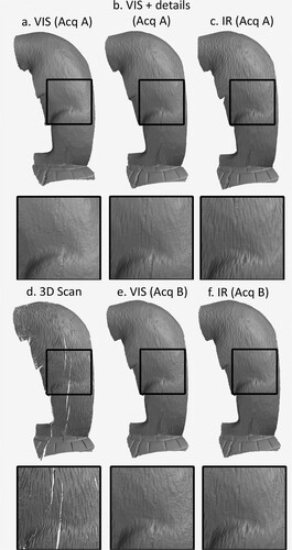
Visually comparing detail views of the resulting models from the structured light scanning and the image-based 3D reconstructions (), the effect of the surface reflections is observed in the VIS reconstruction as a rougher surface than the IR reconstruction. The reduced effect of the surface reflections in the IR input images has improved the recording of the geometry.
The structured light scanner has the increased potential of recording fine detail because details can be resolved to the level of one black and one white pixel. Image-based 3D reconstruction relies on averaging over a 2D image patch as part of the processing. This can result in a smoothing effect as seen with the carved detail of the fur in the image-based 3D reconstructions (both VIS and IR). Structured light scanning is not doing the same averaging of the image-based 3D reconstruction processing increasing the potential for recording fine detail, but the scanned data has holes where information is not recorded from the depth of the carved features. The recording of fine detail in an image-based 3D reconstruction could be improved by increasing the recording resolution by decreasing the camera-object distance and/or changing the lens focal length (as seen with the improved GSD of 0.04 mm/px for the Acquisition A detail images).
There are several differences between Acquisition A and B (lens, lighting setup, and image networks), so the comparison of the resulting data needs to be done with caution. Visual comparison shows that the details of the crack and the carved details of the fur for both the VIS and IR reconstructions from Acquisition B are not as well resolved as Acquisition A (). This can be linked to the inclusion of detail images in Acquisition A. The inclusion of detail images in the input image set increased the resolution as seen with the estimated GSDs (). The Acquisition A VIS detail images improve the GSD to 0.04 mm/px compared to the 0.12 mm/px for Acquisition B. The visual comparison shows that more detailed images of the crack and the carved fur could improve the reconstruction (). This is not surprising, but it provides indications on how the imaging study could be improved with the acquisition of future datasets (see section 3.3). It also shows the difficulty in acquiring repeatable, scientifically valid 3D data for comparison. The level of detail for the second acquisition is insufficient for monitoring the cracking, but it provides evidence of improved 3D reconstruction by using IR images. The VIS results for both imaging campaigns show increased surface noise (seen as a rougher surface) when visually compared to the IR results. Despite the difference in the number of input images (), the IR model from Acquisition A shows improved results compared to the VIS reconstructions. Given similar image networks for Acquisition B, the IR reconstruction confirms improved results compared to the VIS results.
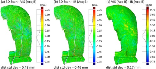
The VIS and IR reconstructions from Acquisition B were compared with the structured light scanned data using GOM Inspect 2018 (). The comparison between VIS and IR models shows better agreement between the image-based techniques (±0.30 mm) (c) than with the reference structure light scan (±0.75 mm) (a, b). This difference is attributable to the structured light system being able to resolve carved surface detail which is smoothed from the averaging in the image-based 3D reconstruction processing.
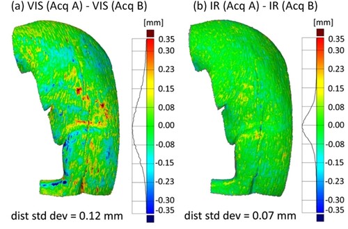
Figure 12. Surface discrepancy map comparisons: (a) structure light scan to VIS model, (b) structure light scan to IR model, and (c) VIS model to IR model.
The area selected for alignment and comparison between reconstructions can impact the results. Large discrepancies between models can result from physical edges (i.e., large cracks in turtle shell) and areas that are blocked from the line of sight for the camera or occluded (i.e., the coyote’s belly). These areas that are not easily or well recorded will result in higher inaccuracies. Since these areas are not important for this assessment of the area of interest, the cracking on the coyote, they can be removed and a smaller, more local area can be used for the alignment and comparison reducing the influence of the larger discrepancies. Note the difference of the area of comparison between and with being a smaller area. In this case, demonstrates the improved surface reconstruction consistency of the IR results in the region of the crack on the coyote. In this local case, the range of discrepancies is reduced from 0.60 mm in the VIS comparison to 0.30 mm in the IR comparison and the standard deviation reduced from 0.12 mm to 0.07 mm. The observed variability is consistent with the largest discrepancies in the VIS comparison and is attributable to the IR data having greater tolerance to surface reflection variation between image networks. The outcome suggests a more forgiving and flexible tool for recording the dark, shiny surface of this object over time where practical imaging setups are likely to vary.
Figure 13. Detailed surface discrepancy maps comparing 3D models between Acquisitions A and B: (a) VIS image data and (b) IR image data. Note that while the range of discrepancies and their location is similar, the comparison between the VIS data is less consistent with a discrepancy standard deviation of 0.12 mm versus 0.07 mm for the IR data.
3.3. Discussion
The two imaging campaigns provided important improvements for the setup and image acquisition of a heritage object to increase the comparability of 3D reconstructions both for assessing VIS and IR image-based 3D reconstructions and for monitoring an object over time. The improvements included more consistency between the image sets using the same lens, lighting, and image networks. While the comparability of the setup was improved, detail images were not acquired for Acquisition B reducing the resulting resolution of the model. This suggests continued areas of improvement for future setups and acquisition by using a combination of images “in the round” and local detail in areas of interest trying to achieve a smaller GSD. GSD offers a tool for estimating the level of detail that can be resolved. Inclusion of photogrammetric coded targets around the object would permit alignment of the two datasets without recourse to fitting between point data sets with different resolutions. Benefits would include a scale reference and provide means of assessing the accuracy and precision of the 3D reconstruction which is independent of the 3D form of the object.
While it is possible and necessary to improve the consistency of the setup and acquisition, it may not be feasible to record datasets with the same equipment, setup, or image network when considering monitoring an object over time (i.e., 5, 10, 15 years). There are also limitations with access to museum objects especially objects on exhibition. If datasets are acquired to measure change over time but using different equipment, setups, or image networks, it is important to understand how the recording technique differs from setup to setup and what level of change can be resolved when accounting for the difference in setups. It would be worth future investigations into physically stable reference targets that could be used to understand the accuracy of a technique and then be able to assess what level of change could be recorded.
This imaging study illustrates the challenge of acquiring high-quality, independent dimensional reference data for assessing the metric quality of 3D cultural heritage documentation (Remondino et al. Citation2014; Toschi et al. Citation2014). Image-based 3D reconstruction is often selected for heritage documentation because it is low-cost, easy to access, and portable. Acquiring reference data with a range-based scanning method may not be an option due to cost, complexity, and portability of range-based scanning equipment. In some cases, the instrumentation used to acquire the reference data may have errors that exceed that of the technique being tested, so the data is not useful as a reference. In the case of the coyote and turtle sculpture, a technically higher accuracy technique was available and used to document the object. However, the optical challenges were the same for both experimental (image-based reconstruction) and reference (structured light scanning) approaches. The dark, shiny surface of the object with fine carved details resulted in a reference data set with incomplete surface coverage seen as holes. While this reference was still used for comparison, the incomplete data set is limited in its ability to assess the accuracy of the 3D reconstructions.
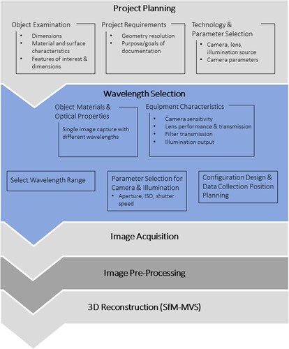
4. Wavelength selection workflow
The imaging study evidenced that the use of a modified camera and wavelength selection can improve image-based 3D reconstruction, and this section will present a wavelength selection workflow. This workflow provides recommendations for how to select imaging wavelengths in order to implement spectral-3D imaging for improved image-based 3D reconstruction of some objects. The workflow () builds on image-based 3D reconstruction pipelines and workflows from Guidance for Good Practice (Historic England Citation2017), Remondino et al. (Citation2013), and Menna et al. (Citation2016). In , the elements of the established pipeline for image-based 3D reconstruction are gray elements: project planning, image acquisition, and 3D reconstruction, while the proposed wavelength selection process is presented in blue and is informed through project planning.
Figure 14. Wavelength selection workflow incorporated into established pipelines/workflows for image-based 3D reconstruction. The elements of the established pipeline for image-based 3D reconstruction are gray elements: project planning, image acquisition, and 3D reconstruction (Historic England Citation2017; Remondino et al. Citation2013; Menna et al. Citation2016). The wavelength selection is presented in blue and it is informed by aspects of the project planning component and is also part of the project design.
4.1. Project planning
The planning phase is the first stage of the project, which involves examining the object and establishing the object characteristics: dimensions, materials, surface characteristics, features of interest, and their approximate dimensions and coverage. This information sets project requirements and establishes technology requirements. Since the multi-image recording of local detail is paramount, image spatial resolution needs to be defined in order to inform the selection of camera, lens, illumination sources, exposure, and the number and probable poses of the camera(s) needed to capture the image network with the selected lens and camera-object distance. In common with all image-based 3D reconstruction projects, this stage requires planning for camera positioning and configuration design based on the object size and the size of the features of interest where GSD can play a useful part in the design.
4.2. Wavelength selection
Wavelength selection considers both the object materials and geometry in conjunction with their optical properties along with the characteristics of components of the imaging system (camera sensitivity, filter transmission, illumination output) to determine wavelengths that would be used to optimize the recording of the object’s geometry. An indication of how materials respond to different ranges of wavelengths can be accomplished by acquiring images of an object using a set of VIS and NIR filters presenting an option for selecting the best wavelength range for recording images for 3D reconstructions. The area of interest on the object must be included in these images (i.e., the crack detail on the coyote) to best inform the wavelength selection.
In this case, individual images recording the object and area of interest () were acquired using the MidOpt bandpass filter kit () fitted to the modified camera and Coastal Optics 60 mm lens (). This resulted in a total of nine images recording wavelength ranges from 400 nm to 1000 nm. These images show how the materials respond differently to different wavelengths. For example, in the image acquired with the BP470 filter, the coyote and turtle both appear dark due to the materials absorbing more light in this range. This image also shows surface reflections that impact local surface contrast around the crack. As the wavelengths get longer, the stain on the turtle becomes more transparent appearing increasingly lighter gray. The images recording in the NIR range (BP800 and BP880 filters) show the crack feature with the most local contrast and clarity suggesting that these ranges would provide improved image data for both image interpretation and 3D reconstruction. Once a wavelength range is selected additional images should be acquired from different views to check for changes in surface reflections and to ensure consistency across the area of interest.
Figure 15. Wavelength selection image set of coyote and turtle sculpture using modified camera and MidOpt bandpass filters (). This image set provides information about the object materials and surface characteristics to inform the selection of imaging wavelengths.
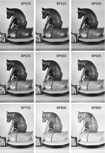
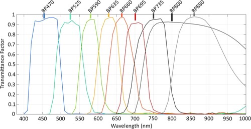
Figure 16. Transmission spectra of VIS and NIR MidOpt filters. Information from MidOpt Website (http://midopt.com).
In addition to the information about the object materials observed from the initial investigative images, information about the equipment characteristics is also important for informing the wavelength selection. The spectral characterization of the modified camera can be helpful to understand where in the spectrum camera sensitivity is at its highest (Webb et al. Citation2018). At areas of lower sensitivity, the images may have higher levels of image noise, or unwanted variation that can impact the image quality. The illumination source spectral output profile and the transmission of the filter (or filters) will also impact performance. Any factors which reduce the amount of light reaching the camera sensor are likely to result in higher levels of image noise.
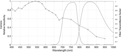
provides an example of how to look at both the camera sensitivity and filter transmission as part of the wavelength selection process. While shows that the NIR images are providing the best contrast for viewing the crack details, the light sensitivity of the modified camera decreases significantly in the NIR. A consideration would be to use the shortest wavelengths that provide increased local contrast of the feature of interests. The BP880 filter provides better contrast of the coyote’s fur and the crack features (); however, the modified camera has ∼50% increased sensitivity in the BP735 range over the BP880 range. Another consideration is the difference in transmission between filters considering the amplitude and width. However, both filters in this case have high transmission and are not particularly narrow. While the examples in this discussion have included bandpass filters with a defined bandwidth, the reflected IR acquisition of the coyote and turtle object presented in the imaging study was with a Peca 910 (equivalent to the Kodak Wratten 87C filter), a long-pass filter that cuts on at about 850 nm (50% transmission).
Figure 17. The transmission of the MidOpt BP735 and BP880 filters compared to the relative sensitivity of the modified camera (Webb et al. Citation2018).
Once the wavelength range is selected based on the object and imaging system, camera parameters and light settings will need to be adjusted for the selected range. The next steps for the image-based 3D reconstruction would be image acquisition and processing, and the wavelength selection process does not necessarily add to or alter these steps.
4.3. Discussion
This research is about improving the input image content for 3D reconstruction. With better images, the reconstruction process should become more reliable delivering consistent results on objects with wavelength dependant surfaces. The presented workflow involves multiple steps and attention to detail, but wavelength selection is a valuable, object dependant tool, able to mitigate what would otherwise be challenging 3D reconstruction problems. The tool is particularly valuable for collections of objects with similar surface properties that can be processed as a group at specific wavelengths. It is important to acknowledge that these results cannot be generalized to all objects or different wavelengths. While the workflow presents steps for establishing the best wavelengths for an object, future work would be required to investigate the potential of different wavelengths for other materials and objects.
Even though this research was conducted with a monochrome modified camera, the wavelength selection process can be used with full-spectrum modified cameras. Full-spectrum modified cameras retain the color filter array, and the red, green, and blue filters have different spectral sensitivities impacting what is recorded in the image at a very local level.
5. Conclusion
The availability, flexibility, and automation that make image-based 3D reconstruction an accessible process, in terms of cost and complexity, also increase the variability in the quality of the resulting 3D models presenting challenges in maintaining 3D output quality and limiting potential uses for the resulting 3D models. Conservation applications for 3D reconstruction, including monitoring condition and measuring change over time, require scientific rigor to establish reliable and accurate models. This research focused on image-based 3D reconstruction for accurate and reliable scientific records for conservation documentation while seeking to maintain the accessibility of imaging and 3D model creation workflows using consumer imaging systems, specifically SfM-MVS for image-based 3D reconstruction and a modified consumer camera for spectral imaging. The quality of the resulting reconstruction relies on the input image quality and the geometry of the image networks, and the research focused on image acquisition specifically looking at local contrast, a modified camera, and wavelength selection.
The imaging study of the coyote and turtle sculpture provided evidence that imaging using a modified camera and selected wavelengths can improve the recording of fine detail for image-based 3D reconstruction. Two imaging campaigns provided important improvements for the setup and image acquisition of a heritage object to increase the comparability of the 3D reconstructions and improve the monitoring of an object over time. It is important that the imaging system setup and image network reflect the required level of detail that needs to be resolved. GSD can provide a rough guide for this and is particularly useful when selecting camera-object distance and lens focal length.
The next step for improved image quality then looked a wavelength. Reflected IR images increased the local contrast and reduced surface reflections improving the recording of the geometry and reducing the variability specifically relating to image networks. Despite differences in the acquisition equipment, setup, and imaging networks between two imaging campaigns, the range in discrepancies was reduced from 0.60 mm when comparing VIS image data to 0.30 mm with IR data and the standard deviation reduced from 0.12 mm to 0.07 mm respectively. The study suggested that the IR data had more tolerance of the differences in the image network than the VIS data, suggesting a more forgiving and flexible option for recording data over time for this object.
The presented wavelength selection workflow provided steps for selecting wavelengths to optimize the camera response, image quality, and object features to minimize the surface discrepancy for 3D reconstruction. The workflow does require multiple steps and takes time, but it can be valuable and solve otherwise challenging 3D reconstruction problems. The wavelength selection workflow is only useful if the surface properties change dramatically with different wavelengths as seen with the coyote and turtle sculpture imaging study and is increasingly useful if there is a group of objects with similar surface properties that would benefit from the workflow.
The imaging study provided only one example using NIR wavelengths to improve image-based 3D reconstruction, but this object is not representative of all heritage objects. Additional imaging studies would provide more examples of materials and wavelengths that would benefit from the technique and those that would not, providing resources and references to heritage professionals interested in this workflow and technique. Future research will include additional recording of the coyote and turtle for monitoring change over time in addition to investigating other objects, materials, and wavelengths.
Acknowledgements
This research was part of a PhD in Heritage Science at the University of Brighton and University College London through the Science and Engineering Arts Heritage and Archaeology (SEAHA) an Engineering and Physical Sciences Research Council (EPSRC) funded Center for Doctoral Training (CDT). Project partners included the Smithsonian’s Museum Conservation Institute and Analytik Ltd. Project advisors included Roger Evans, Stuart Robson, Robert Koestler, and Ian Laidlaw with support from Paula DePriest, Lindsay MacDonald, Dean Few, and Danny Garside. The Smithsonian Digitization Program Office (DPO) provided access and use of the structured light scanner, and Jon Blundell provided support. Amber Kerr (SAAM Head of Conservation), Helen Ingalls (retired SAAM Objects Conservator), and Leslie Umberger (SAAM Curator, Folk and Self-Taught Art) provided additional support and assistance for the imaging study of the coyote and turtle sculpture. None of this would have been possible without the inspiring work, passion, and example of Melvin J. Wachowiak (1958-2014) and David Arnold (1951-2016).
Disclosure statement
No potential conflict of interest was reported by the author(s).
Additional information
Funding
Notes on contributors
E. Keats Webb
E. Keats Webb is the imaging scientist at the Smithsonian’s Museum Conservation Institute (MCI) where she uses scientific and computational imaging to aid in the research and conservation of the Smithsonian collections. Keats has a PhD from the University of Brighton and an MRes from the University College London as part of the Science and Engineering in Arts Heritage and Archaeology Centre for Doctoral Training (SEAHA CDT). Address: Smithsonian’s Museum Conservation Institute, 4210 Silver Hill Rd., Suitland, MD 20746, USA. Email: [email protected]
Stuart Robson
Stuart Robson is RAEng/Airbus Professor of Large Volume Metrology at University College London where he leads the 3DImpact research group. His research focus is on the development of photogrammetry and optical measurement techniques for a wide range of applications including high accuracy engineering measurement, medical and biological metrology and 3D color cultural heritage recording. He has a track record of close working with NASA, Airbus and NPL. Email: [email protected]
Roger Evans
Roger Evans is a Reader in Computer Science in the School of Architecture Technology and Engineering, University of Brighton, UK, co-director of the EPSRC Centre for Doctoral Training in Science and Engineering in Arts Heritage and Archaeology Centre for Doctoral Training (SEAHA CDT) and a member of the Centre for Secure, Intelligent and Usable Systems (CSIUS). His research explores applications of computer technology, particularly to problems which involve the use of natural languages and digital information architectures. He has applied this work in a range of cultural heritage settings, in collaboration with heritage partners including The National Archive, the Natural History Museum, the British Film Institute, the BBC and Historic England. Email: [email protected]
Ariel O’Connor
Ariel O’Connor is an Objects Conservator at the Freer Gallery of Art and Arthur M. Sackler Gallery, the Smithsonian's National Museum of Asian Art (NMAA). Prior to joining NMAA, Ariel was Senior Objects Conservator at the Smithsonian American Art Museum from 2016–2022 and held appointments as Objects Conservator at the Smithsonian National Air and Space Museum, the Walters Art Museum, the Harvard Art Museums, and the Metropolitan Museum of Art. Her research focuses on materials and technology in archaeological Asian art, with a particular interest in early metallurgy, casting, and inlay techniques. She graduated with an MA and CAS in Art Conservation from Buffalo State College. E-mail: [email protected]
Notes
1 PTB, the Physikalisch-Technische Bundesanstalt, is the national metrology institute of Germany, and NIST, the National Institute of Standards and Technology, is part of the United States Department of Commerce.
References
- Abate, Dante, Fabio Menna, Fabio Remondino, and Maria Grazie Gattari. 2014. “3D Painting Documentation: Evaluation of Conservation Conditions with 3D Imaging and Ranging Techniques.” ISPRS Technical Commission V Symposium. International Archives of the Photogrammetry, Remote Sensing and Spatial Information Sciences. Riva del Garda. 1–8. doi:10.5194/isprsarchives-XL-5-1-2014
- Andrews, David, Jon Bedford, and Paul Bryan. 2015. Metric Survey Specifications for Cultural Heritage. 2nd ed. Swindon: Historic England.
- Dellepiane, Matteo, Nicoló Dell’Unto, Marco Callieri, Stefan Lindgren, and Roberto Scopigno. 2013. “Archeological Excavation Monitoring Using Dense Stereo Matching Techniques.” Journal of Cultural Heritage 14: 201–210.
- Ingalls, Helen. 2017. Personal communication. Conservation Department, Smithsonian American Art Museum, Washington, DC.
- Peca Products. n.d. IR-UV Filters. Accessed November 18, 2021. http://www.ir-uv.com/iruv.html
- Historic England. 2017. Photogrammetric Applications for Cultural Heritage: Guidance for Good Practice. Swindon: Historic England. https://historicengland.org.uk/images-books/publications/photogrammetric-applications-for-cultural-heritage/
- James, Mike R., Stuart Robson, Sebastian d’Oleire-Oltmanns, and U. Niethammer. 2017. “Optimising UAV Topographic Surveys Processed with Structure-from-Motion: Ground Control Quality, Quantity and Bundle Adjustment.” Geomorphology 280: 51–66.
- MaxMax.com - Llewellyn Data Processing (LDP LLC). n.d. Cameras. Accessed November 18, 2021. https://www.maxmax.com/maincamerapage
- Menna, Fabio, Erica Nocerino, Fabio Remondino, Matteo Dellepiane, Marco Callieri, and Roberto Scopigno. 2016. “3D Digitization of an Heritage Masterpiece: A Critical Analysis on Quality Assessment.” XXIII ISPRS Congress. International Archives of the Photogrammetry, Remote Sensing and Spatial Information Sciences, Prague, July 12-19, 675–683.
- Remondino, Fabio. 2011. “Advanced 3D Recording Techniques for the Digital Documentation and Conservation of Heritage Sites and Objects.” Change Over Time 1: 198–214.
- Remondino, Fabio, and Sabry El-Hakim. 2006. “Image-Based 3D Modelling: A Review.” The Photogrammetric Record 21: 269–291.
- Remondino, Fabio, Fabio Menna, Anestis Koutsoudis, Christos Chamzas, and Sabry El-Hakim. 2013. “Design and Implement a Reality-Based 3D Digitisation and Modelling Project.” Digital Heritage International Congress, Marseille, France, October 28 - November 1, Volume I, 137-144. Marseilles: Institute of Electrical and Electronics Engineers, Inc.
- Remondino, Fabio, Alessandro Rizzi, Luigi Barazzetti, Marco Scaioni, Francesco Fassi, Raffaella Brumana, and Anna Pelagotti. 2011. “Review of Geometric and Radiometric Analyses of Paintings.” The Photogrammetric Record 26 (136): 439–461.
- Remondino, Fabio, Maria Grazia Spera, Erica Nocerino, Fabio Menna, and Francesco Nex. 2014. “State of the Art in High Density Image Matching.” The Photogrammetric Record 29 (146): 144–166.
- Robson, Stuart, Spike Bucklow, Neil Woodhouse, and Helen Papadakia. 2004. “Periodic Photogrammetric Monitoring and Surface Reconstruction of a Historical Wood Panel Painting for Restoration Purposes.” XX ISPRS Congress. International Archives of the Photogrammetry, Remote Sensing and Spatial Information Sciences, Istanbul, July 12-23, 395–401. https://www.isprs.org/proceedings/xxxv/congress/comm5/papers/585.pdf
- Sapirstein, Philip, and Sarah Murray. 2017. “Establishing Best Practices for Photogrammetric Recording During Archaeological Fieldwork.” Journal of Field Archaeology 42 (4): 337–350. doi:10.1080/00934690.2017.1338513.
- Schroer, Carla, Mark Mudge, and Marlin Lum. 2017. “Photogrammetry Training: Practical, Scientific Use of Photogrammetry in Cultural Heritage.” Training Manual.
- Toschi, Isabella, Alessandro Capra, Livio De Luca, J. A. Beraldin, and Luc Cournoyer. 2014. “On the Evaluation of Photogrammetric Methods for Dense 3D Surface Reconstruction in a Metrological Context.” ISPRS Technical Commission V Symposium. ISPRS Annals of the Photogrammetry, Remote Sensing and Spatial Information Sciences, Riva del Garda, Italy, June 23-25, 371–378. doi:10.5194/isprsannals-II-5-371-2014
- Untitled (Coyote and Turtle). After 1930. Smithsonian American Art Museum (SAAM) Collections Database. Accessed November 18, 2021. https://americanart.si.edu/artwork/untitled-coyote-and-turtle-25440
- Webb, E. Keats. 2020. “Optimising Spectral and 3D Imaging for Cultural Heritage Documentation Using Consumer Imaging Systems.” PhD thesis, University of Brighton.
- Webb, E. Keats, Stuart Robson, Lindsay Macdonald, Danny Garside, and Roger Evans. 2018. “Spectral and 3D Cultural Heritage Documentation Using a Modified Camera.” ISPRS TC II Mid-Term Symposium “Towards Photogrammetry 2020.” International Archives of the Photogrammetry, Remote Sensing and Spatial Information Sciences, Riva del Garda, Italy, June 4-7, 1183–1190. doi:10.5194/isprs-archives-XLII-2-1183-2018