Abstract
Illegal pumping from underground reservoirs is approached as an inverse problem. The procedure seeks among a set of suspected potential areas the ones from which water is effectively pumped out (or in) and at what rate does this take place? Influence coefficient and finite element are combined in order to simulate the aquifer response to hypothetical pumping scenarios. Then the optimal scenario which makes of simulated head distribution the best fit to the observed headset is retained as solution to the foregoing question. This optimal scenario is derived by minimizing the classical least squares error using the Levenberg-Marquardt Algorithm (LMA). Under the conditions of the treated aquifer example it is observed that LMA is non-convergent unless a regularizing measure is taken during the calculation of the correction applied to the parameter-vector between two successive iterations. The procedure is tested with uniform and non-uniform pumping. In both cases, it yields good identified pumping rates within the observation period, but its performance deteriorates markedly for the rates corresponding to the days when no monitoring well is yet active.
Citation Saffi, M. & Cheddadi, A. (Citation2010) Identification of illegal groundwater pumping in semi-confined aquifers. Hydrol. Sci. J. 55(8), 1348–1356.
Résumé
L'identification des pompages illégaux à partir des réservoirs souterrains est approchée comme un problème inverse. La procédure consiste à chercher parmi une série de positions potentielles suspectes, celles d'où l'eau est effectivement pompée (ou injectée) et avec quel débit cela a-t-il lieu? Les coefficients d'influence et la méthode des éléments finis sont combinés pour simuler la réponse de l'aquifère à des scénarios de pompage hypothétique. Ensuite, le scénario optimal qui rend la distribution du potentiel hydraulique simulé la meilleure approximation de celle observée est retenu comme réponse à la question soulevée. Ce scénario optimal est obtenu indirectement en minimisant l'erreur au sens des moindres carrés en utilisant l'Algorithme de Levenberg-Marquardt (ALM). Sous les conditions de l'exemple considéré il est remarqué que l'ALM ne converge pas à moins qu'une mesure régularisante est prise lors du calcul de la correction appliquée au vecteur des paramètres entre deux itérations successives. La procédure est testée sur des scénarios de pompage uniforme et non uniforme. Dans les deux cas elle identifie correctement le débit pompé pour les jours d'observation, mais ses performances se détériorent nettement vis-à-vis des débits correspondants aux jours où les observations n'ont pas encore été commencées.
INTRODUCTION
Identification of illegal pumping, always carried out under camouflage, remains among essential measures for fair groundwater sharing. In practice, the authority managing an aquifer may have doubts about possible illegal groundwater abstractions. Typically, suspicion may grow around private property such as farms and factories where water pumping and wastewater injection is likely to occur. In such cases, a hydraulic head monitoring campaign can be run over a set of wells to help identify the locations from which the aquifer is probably being tapped.
From the governing equation viewpoint the recovery of the source term lies in the inverse problem category, and meets the second type of inverse problems in Sun's classification (Sun, Citation1999). The first and the third types are, respectively, identification of physical parameters such as transmissivity, and identification of initial and/or boundary conditions. Sun referred to the fourth type as any combination of the previous three.
It is noteworthy that identification of groundwater pollution sources has received much attention, and many aspects of the question have been debated (Gorelick et al., Citation1983; Aral & Guan, Citation1996; Neupauer et al., Citation2007). However, its counterpart, the problem of identifying illegal wells, still lags behind. This work attempts to contribute to addressing this issue by combining calibrated numerical models and observations. It extends the problem formulated and solved for a one-dimensional semi-confined aquifer by Saffi & Cheddadi (Citation2007). So, given a reliable calibrated direct code and a record of observed heads, the point is to arrive at the well configuration (locations and magnitudes) which gives the best possible reproduction of the monitored hydraulic head.
The first section of this paper formulates the problem within an optimization framework. Then a test problem dealing with a two-dimensional (2-D) semi-confined aquifer is introduced, followed by a discussion. The latter is carried out first with uniform pumping, in order to illustrate through the considered example why the Levenberg-Marquardt Algorithm (LMA) diverges, and also to see which regularizing measure is required to make it converge. The discussion closes with the results of a non-uniform pumping and sensitivity analysis.
PROBLEM STATEMENT
Two kinds of wells are distinguished. Legal wells (LW), often used to satisfy municipal water demand, are known in number, location and magnitude. In the following they are represented by a vector
, where Q
LWj
(t) stands for the pumping rate of the jth legal well at time t, and
is their total number.
Illegal wells are the areas from which water is abstracted or injected into the aquifer without prior permission. So, they are neither known in number nor in magnitude or location. However, here we refer to potential illegal wells (PIW), being the locations which are thought to be subject to illegal pumping. Similarly, PIWs are represented by a vector , where P
PIWj
(t) denotes the magnitude of the jth PIW and
is the number of such wells. The parameter-vector
P
(t) contains the problem unknowns to be determined.
Now, given a well field configuration ( P (t), Q (t)), the hydraulic head distribution h (t) over a flow region Ω is the solution to the following dynamical equation with the indicated initial condition (Pinder & Gray, Citation1977; Bear, Citation2007):
In Equationequation (2)(B2),
h
(s) = (h
1
(s), h
2
(s), …, hn
(s))
T
, where hj
(s) denotes the hydraulic head in node j and at time s;
is the vector of nodal hydraulic head when all illegal wells are inactive; Δt is the discretization time step; and
G
(s) stands for the matrix of influence coefficients at time s. The vector
contains the known pumping rates with Q
LWj
(k) referring to the jth LW at time k and s
max being the number of time levels over which the system is considered. Likewise, the vector
represents the unknown pumping rates where P
PIWj
(k) refers to the jth PIW during time k. Practically,
G
(s) is computed only once by solving system (1), in which boundary and initial conditions are zeroed; and all the sources and sinks are replaced with a unit Dirac delta function. Then,
G
(s) is stored in a separate file ready-for-use alongside Equationequation (2)
(B2) for any potential scenario
P
. In this way, a great deal of computation time is saved during inverse problem resolution. A full account of this is found in Illangasekare & Morel-Seytoux (Citation1982). Explanatory details on the structure of the matrix
G
(s) are also presented in Appendix A.
The aquifer system is observed through monitoring wells MW1, MW2,…, MW
, over a period of time [s
min, s
max]; where s
min corresponds to that time step when the first head observation is made. Let [h
MWj
obs](s) denote the observed head at monitoring well MWj and time step s for
and s
min ≤ s ≤ s
max. For convenience, the [h
MWj
obs](s) terms are gathered in the
vector defined by:
In parallel, the simulated hydraulic head at MWj and time step s, i.e. the component h
MWj
(s) of the vector
h
(s) of Equationequation (2)(B2), will be denoted [h
MWj
sim](s). Again, the [h
MWj
sim](s) terms are put in the following
vector:
Next, a feasible model input P which achieves the best fit between the foregoing vectors h sim( P ) and h obs, is sought by minimizing the criterion:
TEST PROBLEM DEFINITION
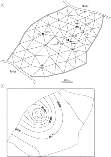
The following example is inspired by Willis & Yeh (Citation1987). (a) displays a hypothetical flow region Ω delimited by two river reaches that impose a constant head of 100 m. The two other (shaded) sections of Ω border are of no-flow type. The aquifer transmissivity and storage coefficient are 1000 m2 d‐1 and 0.01 respectively. Semi-confining layer hydraulic conductivity and thickness, Ka
and ma
, are set equal to 0.01 m d‐1 and 30 m, respectively. The external hydraulic head Ha
= 100 m. The flow governing equation is recalled in Appendix A. Water is pumped from the only legal well LW1 located in the node 28 at a daily rate of 10 000 m3 (i.e. , the number of legal wells is equal to 1). Steady-state conditions are assumed to prevail then.
Fig. 1 (a) Aquifer system configuration: black circle denotes the only legal well (LW1); stars indicate potential illegal wells (PIW); unfilled circles show monitoring well (MW) positions. (b) Initial hydraulic head distribution taken as the steady-state solution to Equationequation (1)(B1) for: Q
LW1 = 10 000 m3 d‐1; and P
PIW1 = P
PIW2 = 0.

At some time level s = 0, two areas around nodes 34 and 44 are suspected to be subject to illegal pumping (i.e. , the number of potential illegal wells is 2). That is, a monitoring campaign was started in
monitoring wells MW1, MW2,…, MW6 located in nodes 26, 36, 43, 25, 50 and 6, respectively, over a 9-day-period of observation that starts at s
min = 7 and ends at s
max = 15 With these data there are more equations than unknowns and problem (5) is over-determined. Synthetic observed heads are obtained by perturbing to 5% the solution of Equationequation (2)
(B2) started from the initial head distribution of (b), with the flow domain segmented into 97 triangular elements using n = 62 nodes and a time step Δt = 1 day.
RESULTS AND DISCUSSION
In the following, the Levenberg-Marquardt Algorithm (LMA) is used to solve minimization problem (5) for the above-defined test problem; first with a uniform illegal pumping of 2500 m3 d‐1 in magnitude for both PIW1 and PIW2 and then with a non-uniform pumping scenario.
After launching the algorithm from several starting points, it is observed that J is nearly constant and takes very small values while Δ P (k) remains large. The term Δ P (k) is the correction applied to the parameter-vector P (k–1) during the kth iteration; it is calculated via equation (B1) (see Appendix B). For instance, the last row of reports that J is as small as 3 × 10‐6 while Δ P (k) is of the order 13 500 m3 d‐1: the algorithm diverges. The cause underlying this poor performance lies in the relationship between Δ P (k) and the subsequent variation J( P (k)) – J( P (k–1)) of criterion J denoted ΔJ (k). From the Taylor series applied to J( P (k) = P (k–1) + Δ P (k)), it may be shown that:
Table 1 The first five iterations of non-regularized LMA for PIW1. Similar results (not reported here) are obtained for PIW2
Table 2 Comparison of Δ1 (k ) and Δ2 (k ) Euclidean norms (in 103 m3 d‐ 1) for the five iterations displayed on Table 1
Now, to turn the previous conceptual reasoning into computer code, an explicit means to quantify Δ P 2 (k) is required. This means is provided by the singular values spectrum of the curvature matrix C of equation (B1). Paragraph 2.3 of Nazareth (Citation1980) adduces mathematical grounds for this. The complete orthogonal factorization of the Jacobian matrix used then should be replaced with the following singular-value decomposition of the matrix C :
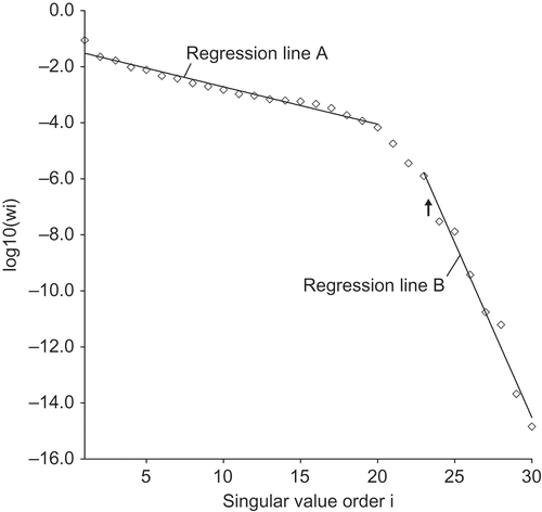
In all, up to some cut-off order M 0 the wi values stay with a same order of magnitude, but beyond the cut-off they drop dramatically. A typical profile of matrix C singular values is depicted in with a corresponding M 0 of 23. In this case C comes from the aquifer example of under uniform pumping. Regression lines A and B in with respective slopes of −0.13 and −1.25 illustrate how sharp is the decline in the magnitude of wi ; M 0 is the threshold which demarcates Δ P 1 (k) from Δ P 2 (k) in the following way:
Fig. 2 Typical profile of singular values wi of the curvature matrix C resulting from the aquifer example of Fig. 1 under uniform pumping of 2500 m3d‐1and a data set perturbed to 5%. The regression lines A and B with slopes −0.13 and −1.25 illustrate how important is the decline in wi magnitude. The black arrow points at the first substantial drop in two successive wi , i.e., w 23 and w 24.

The foregoing Δ P 1 (k) expression meets equation (14.3.17) in Press et al. (Citation1989). Vector b originates in the classical equations underlying the LMA. It is made explicit in Appendix B. The terms U *j and V *j are the jth column vectors of matrices U and V , respectively. Their numerical values are known from the above mentioned commands and procedures.
At this stage, a definite choice of M
0 remains in order to make Equationequation (8)(8) fully operational. Press et al. (Citation1989) pointed out that no standard rule is available for this task, and the user is called to exercise some of his discretion. Actually the value of M
0 is ad hoc to the treated technical problem. Practically, through the aquifer example under work, a rough range of three or at most four potential values of M
0 is unmistakable; afterwards the exact value can be efficiently determined by trial and error. Yet, even a naked-eye study of shows that the first large gap between two successive values occurs at w
23.
Actually, () corresponds to the number of equations in system (B1) which are nearly redundant, so they are at best useless during Δ
P
(k) calculation. They are so because of the information lost before the head monitoring campaign was started, i.e. (s < s
min). This is again confirmed by heuristic code runs conducted with various s
min values. It seems that the smaller is s
min the larger is M
0. A good preliminary estimate of M
0 for this problem would be the dimension of the parameter-vector (
), less the number of days during which no head observation was made (i.e. s
min).
Numerical experiments under regularized Δ P (k)
Now the LMA is rerun taking care at each iteration to drop Δ P 2 (k) while solving system (B1). The new estimate P (k–1) of the parameter-vector and the corresponding regularized correction Δ P (k) are listed in . Notice that both J( P (k–1)) and ||Δ P (k)||2 decrease correspondingly, and overall P (k–1) converges to the correct rate of 2500 m3 d-1.
Table 3 The first five iterations obtained with regularized LMA (M 0 = 23) for PIW1
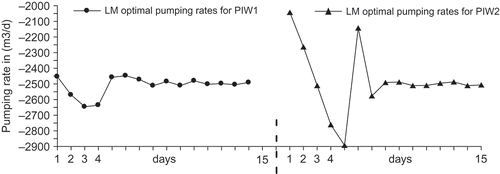
depicts the identified pumping rates for both PIW1 and PIW2 over the considered 15-day period. It appears that the pumping rates corresponding to days s, between s min = 7 and s max = 15, are well identified for both wells, while those relative to days s out of the observation period (s < s min) are poorly identified. Moreover, because of the storage effect (aquifer memory), observed heads during early days of the campaign (e.g. s = 7 or 8) still carry some information on the pumping rates of the latest unmonitored days (e.g. s = 5 or 6). So, depending on how long/short the system memory is, the general trend is this: prior to s min the farther one goes back in time the less accurate the identified pumping becomes, as it is exemplified on PIW2 in particular during the first three or four days ().
Fig. 3 Identified pumping rates for the aquifer of Fig. 1 under a uniform pumping of 2500 m3 d‐1. Data are perturbed to 5%. Large oscillations are shown on the first 6 days when the hydraulic head is not monitored yet.

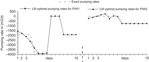
reports the results of a second example: data are perturbed to 5% and the methodology is similar to the previous case except that the pumping magnitudes at PIW1 and PIW2 are made to vary with time as shown by the dashed line. Again LMA performs well within the observation period [s min, s max] but it poorly identifies the pumping rates lying outside of it. Moreover, a similar test to that carried out by Saffi & Cheddadi (Citation2007) in which data are perturbed to 2.5%, 5% and 7.5%, shows that the regularized pumping rates are not obscured by the added noise though the quality of the results slightly deteriorates.
CONCLUSION
This work formulates and solves the problem of illegal pumping in 2-D semi-confined aquifers. It aims to determine pumping rates and the locations from which groundwater is being illegally abstracted among a known and finite set of suspected areas.
The question comes down to identifying the vector P of hypothetical pumping rates P PIWi (s) at potential illegal well number i and time step s, 1 ≤ s ≤ s max, from a set of observed heads [h MWj obs](k) carried out at monitoring well j and time step k (s min ≤ k ≤ s max).
Parameter-vector
P
is determined by minimizing the criterion J of Equationequation (5)(5) using the LMA. As a first approach the procedure is explained using a hypothetical aquifer example in which it is assumed that the main parameters of the system alongside initial and boundary conditions are accurately known. Under these conditions it appears that:
-
The problem is well-posed with respect to magnitudes P PIWi (s) corresponding to day s for the monitoring campaign (s min ≤ s ≤ s max), while it is ill-posed for P PIWi (s) with s < s min.
-
The LMA converges if, for each iteration, only the most significant M 0 singular values wi of the curvature matrix are taken into account during the calculation of the correction applied to the parameter-vector.
-
A rough surrounding of the cut-off order M 0 can be delineated from the wi profile; then the exact value is practically determined by trial and error. It is observed that M 0 is strongly linked to s min, the number of days when no head observation was made. The shorter s min, the larger is M 0 and the more well-posed is the problem.
However, the problem should be investigated under less restricting hypotheses and the effect of error propagation in the estimation process needs assessment.
REFERENCES
- Aral , M. and Guan , J. 1996 . Genetic algorithms in search of groundwater pollution sources . Advances in Groundwater Pollution Control and Remediation, 347–369. Berlin: Springer Verlag, NATO Science Partnership Sub-Series 2, vol. 9. ,
- Bear , J . 2007 . Hydraulics of Groundwater , New York : Dover Press .
- Gorelick , S. M. , Evans , B. and Remson , I . 1983 . Identifying sources of groundwater pollution: an optimisation approach . Water Resour. Res. , 19 ( 3 ) : 779 – 790 .
- Illangasekare , T. and Morel-Seytoux , H. J . 1982 . Stream-aquifer influence coefficients as tools for simulation and management . Water Resour. Res. , 18 ( 1 ) : 168 – 176 .
- Maddock , T. III . 1972 . Algebraic technological function from a simulation model . Water Resour. Res. , 8 ( 1 ) : 129 – 134 .
- Nazareth , L . 1980 . Some recent approaches to solving large residual nonlinear least squares problems . SIAM Rev. , 22 ( 1 ) : 1 – 11 .
- Neupauer , R. M. , Lin , R. and O'Shea , H . 2007 . Conditioned backward probability modelling to identify sources of groundwater contaminants subject to sorption and decay . Water Resour. Res. , 43 ( 11 ) : W11403
- Pinder , G. F. and Gray , W. G. 1977 . Finite Element Simulation in Surface and Subsurface Hydrology , Orlando, FL : Academic Press .
- Press , W. H. , Flannery , B. P. , Teukolsky , S. A. and Vetterling , W. T . 1989 . Numerical Recipes in Pascal , Cambridge : Cambridge University Press .
- Saffi , M . 2008 . Contribution of Influence Coefficients in Solving Groundwater Problems , Rabat, Morocco : Mémoire d'Habilitation Universitaire, Ecole Mohammadia d'Ingénieurs .
- Saffi , M. and Cheddadi , A . 2007 . Explicit algebraic influence coefficients: a one-dimensional transient aquifer model . Hydrol. Sci. J. , 52 ( 4 ) : 763 – 776 .
- Sun , N.-Z . 1999 . Inverse Problems in Groundwater Modeling , Dordrecht : Kluwer Academic Publishers .
- Willis , R. and Yeh , W. W-G. 1987 . Groundwater Systems Planning and Management , Englewood Cliffs, NJ : Prentice-Hall .
APPENDIX A
Semi-confined flow governing equation
The mathematical model considered in this paper rules 2-D semi-confined flows. It is written (Bear, Citation2007):
Matrix of Influence coefficients, G (s)
In this work, the matrix
G
(s) of Equationequation (2)(B2) comes from finite element discretization of the above equation (A1). It is a concatenation of
sub-matrices (
is the number of PIWs). Each sub-matrix is associated with a PIW and contains s
max columns and n rows, as explained by equation (A2); s
max is the number of time levels over which the aquifer system is considered; and n is the number of grid nodes.
Consequently,
G
(s) is a array. The general term G
p,PIWk
s,i
is read as the aquifer response at time level s, in node p to a unit stress applied at time level i in the PIWk under homogeneous boundary and initial conditions. In other words, G
p,PIWk
s,i
is the following derivative of the hydraulic head with respect to pumping:
Matrix G (s) is relative to the present time step s, so its columns beyond (s + 1) are conventionally nil (i.e. G p,PIWk s,i = 0 for i ≥ s + 1). A detailed procedure to compute the influence coefficients is found in Maddock (Citation1972).
APPENDIX B
Computation of correction Δ P
The correction Δ
P
applied to parameter-vector
P
while minimizing the criterion J of Equationequation (5)(5) using the Levenberg-Marquardt algorithm is solution to the following set of equations (Press et al.,
Citation1989):
The curvature matrix and the vector
are defined for the criterion J by:
Pi
is a provisional notation of the ith component of the parameter-vector
P
as introduced in Equationequation (2)(B2); δ
ij
is the Kronecker symbol; and λ is an adaptable parameter. Further details are given by Press et al., Citation1989, pp. 574–576).
