ABSTRACT
The problem of transmission of pressure head through the zone of tension saturation in the Lisse effect (LE), i.e., the rapid response of groundwater level to pressurized pore air in the unsaturated zone, is investigated theoretically and experimentally. From the law of conservation of energy and the continuity equation, a one-dimensional diffusion equation is derived for transmission of pressure head through the zone of tension saturation. The solution to the equation is the pressure head at any point below the upper boundary of the zone of tension saturation and at any time after the compressed pore air pressure is imposed on the boundary. The key parameter, which determines the behaviour of transmission of pressure head, is the newly proposed pressure head diffusivity coefficient. The theoretical results agree with the experimental results, obtained from laboratory column experiments in three physically different soils.
Editor Demetris Koutsoyiannis Associate editor Xi Chen
Notation and Abbreviations
Pressure head diffusivity coefficient [L2T−1]
Complementary error function
Energy content in the zone of tension saturation [ML2T−2]
Time-rate change in potential energy content in the zone of tension saturation [ML2T−3]
Gravitational acceleration [LT−2]
Pore air pressure head [L]
Pore air entry pressure head of the soil [L]
Pore water pressure head [L]
Saturated hydraulic conductivity [LT−1]
Time coordinate [T]
Time to peak response of the pressure head in pore water [T]
Unit cross-section area of the zone of tension saturation [L2]
Space coordinate [L]
Depth of unsaturated zone [L]
Depth of ponded water on the soil surface [L]
Depth of the zone of tension saturation [L]
Lower boundary of the zone of tension saturation (see )
Boundary, soil surface
Upper boundary of the zone of tension saturation
Water table or the phreatic surface (see )
Soil water content [L3L−3]
Residual soil water content [L3L−3]
Saturated soil water content [L3L−3]
Pressure head conductivity of soil pore water [MT−3]
Pore size distribution index in Brooks–Corey equation
Density of water [ML−3]
Bulk density of soil [ML−3]
Porosity of the porous medium [L3L−3]
Brooks−Corey
Coarse sand (0.50–2.00 mm)
Fine sand (0.053–0.25 mm)
Groundwater (in some cases referring to water below the water table and in some cases referring to all the water below the ground)
Medium sized sand (0.25–0.50 mm)
metres
millimetres
miniature tensiometer
pore air pressure probe
Pressure head
Silt and clay (<0.053 mm)
Time domain reflectometry
Unsaturated zone
Water table
Zone of tension saturation
1. Introduction
1.1. The Lisse effect
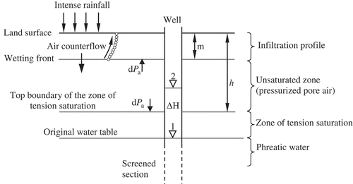
The Lisse effect is defined as the rapid rise of groundwater levels as a result of the action of entrapped and pressurized pore air, ahead of a wetting front, on the water table during intense rainfall at the ground surface (). The Lisse effect is likely to occur where the water table (phreatic surface) is deep enough to allow sufficient depth of an unsaturated zone, with a continuous volume of pore air, above the zone of tension saturation. During an intense rainfall event, or a flooding event, on the ground surface, a wetting front may cap the near surface. If the lateral escape routes of air ahead of a wetting front are limited, due to the tortuosity of the pathways, and the vertical counterflow of air is impeded by the infiltration profile, further downward movement of the wetting front compresses and increases the pressure in the air. The pressure in the air is transferred to the water table, resulting in a water level rise in a well screened below the water table (). Therefore, in the Lisse effect, there are two domains of water masses that may be affected by the compressed pore air, namely (1) the water in the infiltration profile and (2) the water in the saturated zone, below the upper boundary of the zone of tension saturation.
Figure 1. The Lisse effect. The rise in water level in a well, ΔH, as result of the action of increased pore air pressure, dPa, on the upper boundary of the zone of tension saturation. m is the depth of the infiltration profile, h is the depth from the ground surface to the top boundary of the zone of tension saturation (modified from Weeks Citation2002).
1.2. Infiltration profile and counterflow of air
The effect of compressed pore air ahead of a wetting front on the infiltration profile, rate of infiltration, and total infiltration has been intensively studied using laboratory column experiments (Powers Citation1934, Peck Citation1965, Vachaud et al. Citation1974, Touma et al. Citation1984, Wang et al. Citation1998), theoretical analysis (Brustkern and Morel-Seytoux Citation1970, McWhorter Citation1971, Wang et al. Citation1997), as well as field observations (Dixon and Linden Citation1972). All these studies demonstrated that the entrapped pore air ahead of a wetting front has an inhibiting effect on infiltration.
With the continued downward movement of a wetting front, a state is reached whereby the pressure in the entrapped air exceeds the pressure head of the infiltration profile above. When this state is reached, some of the entrapped air counterflows upwards against the infiltration profile. This results in a two-phase flow phenomenon, i.e., simultaneous downward transmission of water and upward transmission of air (Powers Citation1934, Peck Citation1965, Brustkern and Morel-Seytoux Citation1970, McWhorter Citation1971, Dixon and Linden Citation1972, Vachaud et al. Citation1973, Citation1974, Morel-Seytoux and Khanji Citation1975, Ishihara and Shimojinia Citation1983, Touma et al. Citation1984, Wang et al. Citation1997 and Wang et al. Citation1998).
1.3. Rapid groundwater level response
The rapid response of groundwater levels to pressurized pore air ahead of a wetting front has been observed in the field (Linden and Dixon Citation1975) and investigated theoretically (Guo et al. Citation2008), as well as experimentally (Waswa et al. Citation2013). This rapid response has been attributed to the contribution of the elevated pressure in air to the pressure potential term in the hydraulic head of the groundwater (Freeze and Cherry Citation1979).
Freeze and Cherry (Citation1979) indicated that the compressed pore air pressure acts directly on the water table, resulting in an equivalent rise in the groundwater level in a well (). Weeks (Citation2002) proposed that the groundwater level rise (ΔH) can be estimated by the equation
The objective of this paper, therefore, is to investigate, theoretically and experimentally, the transient behaviour and the physical processes involved in the response of a groundwater table as a result of the action of compressed pore air on the upper boundary of the zone of tension saturation.
2. Theoretical approach
2.1. Assumptions
The equations derived and presented in this section are based on the following assumptions: (1) the porous medium is homogeneous and isotropic on the averaging scale; (2) the porous medium is rigid and non-deformable in space and time (the physical properties of the porous medium are spatially and temporally constant); (3) the height of the zone of tension saturation, above the water table, is equivalent to the pore air entry pressure head, hb, of the porous medium and as defined by the Brooks−Corey equation (Brooks and Corey Citation1964); (4) below the upper boundary of the zone of tension saturation, the pressure head varies linearly with depth; (5) water is a continuous phase beneath the upper boundary of the zone of tension saturation i.e., , for
. Similarly, it is assumed that air is a continuous phase above the upper boundary of the zone of tension saturation, i.e.,
, for
; (6) water and air are homogeneous and immiscible and their viscosities are constant; (7) the change in pore air pressure in the unsaturated zone, above the upper boundary of the zone of tension saturation, is uniform and does not vary with depth.
2.2. Derivation of differential equation of conduction of pressure head through the zone of tension saturation
An idealized zone of tension saturation, as shown in , is considered. The zone of tension saturation is of uniform saturation, i.e.,
Figure 2. Idealized free body diagram of the zone of tension of saturation (ZTS) used in the derivation of the differential equation of diffusion of pressure head through pore water. UZ is unsaturated zone and GW is groundwater (under positive pressure).
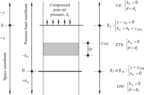
The vertical space coordinate is oriented positive downwards, with its origin at the upper boundary of the zone of tension saturation. The pressure head coordinate is also oriented positive downwards, but with its origin at the water table.
Within this framework, the unsaturated zone (UZ), the zone of tension saturation and the phreatic zone can be defined as
The boundaries of the zone of tension saturation can be defined by the space and pressure head coordinates. The upper boundary of the zone of tension saturation (ZTS), , is defined as
Energy equation
It should be noted that the fundamental property here is pressure head (potential energy per unit weight of water), which cannot be described by a velocity field of water. This is because pressure head is transmitted through water by diffusion transmission and without the movement of water particles. Therefore, the flux of pressure head occurs without an association with the water velocity field. In the basic law of conservation of energy for the entire height of the zone of tension saturation, , the rate of change of pressure head within the zone of tension saturation is equal to the net amount of potential energy transmitted through the two boundaries,
and
. Consider an infinitesimal section of height
in the interval
. In this infinitesimal section, the magnitude of potential energy (
) is proportional to the weight of water and the pressure head,
[L]:
The Fourier law of heat conduction, for our present case, can be stated as: the rate of potential energy propagating into a body (the zone of tension saturation) through a small surface element on its boundary is proportional to the area of that element and the outward normal derivative of the pressure head at that location. In other words, the diffusion rate of potential energy through a surface/boundary is proportional to the negative pressure head gradient across the surface/boundary. Therefore, the net potential energy through the boundaries and
is
where, [MT−3] is the pore fluid pressure head conductivity, which is the time rate of potential energy transfer through a unit thickness of the material (the zone of tension saturation) per unit area per unit pressure difference.
is analogous to thermal conductivity in thermodynamics (Yunus Citation2003).
From the law of conservation of energy
For smooth material properties, i.e., if and
are continuous with continuous first derivatives, the solution
is also continuous with continuous first partial derivatives
and
(Kevorkian Citation2000). Hence, equation (11) can also be written in the following form, after expressing the right-hand side as the integral of a derivative:
2.3. Initial and boundary conditions
Initial conditions
Based on the assumption that the pressure head, below the upper boundary of the zone of tension saturation, , linearly varies with depth, the initial condition can be written as
Here, the expression for space limits is for any depth of the saturated zone, below the upper boundary of the zone of tension saturation. Note that the initial condition, equation (16), is valid for any depth below the upper boundary of the zone of tension saturation, and is independent of the depth of the saturated zone, or the position of the lower boundary.
Boundary conditions
The upper boundary condition is defined by
where [L] is the imposed compressed pore air pressure head.
It is also important to pose the semi-infinite boundary condition, where the change in pressure head as a result of compressed pore air pressure at the boundary becomes negligible as the depth increases. This can be written as
It is important to note that the change in pressure head at any point within a static, homogeneous and incompressible fluid depends on the depth of that point relative to some reference plane, and is not influenced by the size and shape of the container (Janna Citation1987). In other words, the position of the lower boundary or the shape of the container does not have any influence on the change in pressure head at a point within the saturated porous media.
2.4. The solution of the differential equation
The solution to equation (14), which can also satisfy the initial and boundary conditions equations (16–18) is
which is analogous to the heat conduction solution described by Carslaw and Jaeger (Citation1959, p. 63). A detailed derivation of equation (19) can be found in Waswa (Citation2013).
Note that the right-hand side of equation (19) consists of two terms: the initial steady-state pressure head and the transient pressure head, as a result of the imposed compressed pore air pressure on the boundary
. In using the model, it will suffice to use and report only the results of the transient pressure head at any specified depth, without including the initial pressure head.
2.5. Estimation of pressure head diffusivity coefficient
By knowing the pressure head diffusivity, it is possible to understand how fast pressure head can be transmitted in a particular medium. In applying equation (19), values of pressure head diffusivity should be known. Here, this parameter is determined by fitting equation (19) to the experimental data, in a methodology similar to that employed by Rasmussen et al. (Citation2000) and Flury and Gimmi (Citation2002). The time of peak response, tp, occurs when the second time derivative of equation (19) is equated to zero, i.e., , which yields
3. Experimental approach
3.1. Material parameters
The unconsolidated porous medium, water and air are the three main materials used in the laboratory experiments. The porous medium comprised a mix of graded silica quartz (SiO2) and clay soil, both of which were obtained from a commercial supplier. The individual grains of the soils were uniform in shape, stable, clean and free of organic matter. The graded silica sand was supplied in two grades, which were predominantly medium sand and fine sand. The clay was kaolin clay powder (china clay), comprising trace mica and quartz. The silica quartz sand and kaolin clay powder had bulk densities of 1500 kg/m3 and 350 kg/m3, respectively.
The two graded silica sands and clay soil were mixed in different ratios, to obtain three physically different types of soils, as shown in . For ease of reference, these soils were named Coarse soil (C), Medium soil (M) and Fine soil (F), as indicated in . Particle size distribution, saturated hydraulic conductivity and the water retention characteristics of the three soils were determined in the laboratory, according to the methods and procedures of Gee and Bauder (Citation1986), Klute (Citation1986) and Klute and Dirksen (Citation1986), respectively.
Table 1. Physical properties of the soils used in the laboratory experiments.
3.2. Experimental apparatus and instrumentation
The physical laboratory model consisted of a column of soil in a vertical PVC pipe with an internal diameter of 30 cm and a height of 210 cm. Seven data take-off ports were installed along the pipe, at 60, 90, 120, 130, 140, 150 and 160 cm below the soil surface, which was at 40 cm below the top of the PVC pipe, as shown in . Henceforth, a data take-off port will be referred to by its position below the soil surface. For example, Port 60 refers to a data take-off port located at 60 cm below the soil surface. The assumptions stated in the derivation of the theoretical equation apply in the laboratory experiment as well.
Figure 3. (a) Laboratory experimental set up. is height of the zone of tension saturation, yuz is height of unsaturated zone, yw is height of water ponding on the soil surface, βss is soil surface, βu is upper boundary of the zone of tension saturation, β1 or βwt is the lower boundary of the zone of tension saturation or the water table (zero pressure line), papp is pore air pressure probe, tdr is time domain reflectometry, and mt is miniature tensiometer. (b) Instrumentation layout.
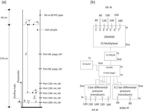
Each data take-off port was installed with a time domain reflectometry (TDR) probe, for the measurement of volumetric water content. Each of the lower five ports was installed with a 0.5 bar miniature tensiometer, for the measurement of soil pore water pressure. Each of the upper two ports was installed with a pore air pressure probe, for the measurement of pore air pressure. A drainage/discharge tube and a piezometer were attached to the column, at a depth of 170 cm below the soil surface, for groundwater discharge and for monitoring of the groundwater level, respectively.
The TDR probe was made of three, 5 mm diameter parallel stainless steel rods, which were embedded into a PVC block, at a separation distance of 17 mm and exposed length of 100 mm. The soil water content data, measured by the TDRs, were recorded and temporarily stored on a CR1000 Campbell Scientific data logger, via a Campbell Scientific TDR100 wave generator and a SDMX50 Multiplexer (). Miniature tensiometers consisted of a 15 mm long ceramic cup with an outer diameter of 5 mm. The open end of the ceramic cup was joined to one end of a 10 cm long PVC tube with the same outer diameter. The other end of the PVC tube was connected to a differential pressure transducer. The data for pore water pressure and pore air pressure were recorded and temporarily stored on a CR1000 Campbell Scientific data logger, via differential pressure transducers of 1 bar Motorola MPX5100DP and 0.1 bar Motorola MPX5010DP, respectively ().
3.3. Experimental description
The experimental procedure described here was carried out on each of the three types of soils described in Section 3.1. The PVC cylindrical pipe was packed with dry soil, in layers of ~55 cm high, to an average bulk density of 1530 kg/m3. After each layer, the wall of the pipe was tapped with the same number of blows, in order to achieve uniform and maximum density and packing. The TDRs and the pore air pressure probes were mounted in the wall of the PVC pipe, before being packed with sand. The ceramic-cup miniature tensiometers, due to their fragility, were inserted after packing the pipe with the soil. After all the probes were seated into the column of soil, the entire wall of the pipe was sealed to an air-tight state with silicone sealant.
Groundwater was introduced to the packed column of soil from the bottom, to minimize the entrapment of encapsulated pore air, which has been found to contribute to disproportionate water table responses (Peck Citation1960). By adjusting the level of the nozzle of the discharge tube, the initial water table was positioned at Port 160, at equilibrium. The equilibrium conditions were determined when there were no changes in the tensiometric pore water pressure. The zone of tension saturation, of which the height was taken to be equivalent to the air-entry pressure value of the soil (), extended above the water table.
With this initial state, the experiment was started by instantaneous ponding of the soil surface with water. Groundwater fluxes, tensiometric pore water pressure, volumetric water content and pore air pressure responses were monitored and recorded at a time-resolution of 20 seconds, starting from the moment that the soil surface was ponded. For each soil type, two experiments were performed with different depths of ponded water, namely 15 cm and 30 cm.
4. Results and discussions
Immediately water was introduced at the soil surface, the pressure in the pore air ahead of the wetting front increased rapidly. The behaviour of the pore air pressure in all the soils was nearly uniform, i.e., increased at nearly the same rate and attained maximum values at almost the same time.
However, the response of the water table (pressure head in the pore water) to pore air pressure was quite different in each soil ( and ). Both the theoretical and the observed results indicate that the rate of response of the water table decreased with the fineness of the soil. For instance, an initial increase in pressure head of 20 cm took about 2 minutes in the Coarse soil, compared with 12 minutes in the Fine soil. A similar trend can be observed in the lag in time between the onset of pore air pressure increase and the onset of the water table response, as indicated by the origins of the pressure curves in . This time lag appears to increase and become more evident with the height of the zone of tension saturation, or the fineness of the soil: whereas the response of the water table in the Coarse soil appears to be instantaneous, the response in the Fine soil exhibits a more distinct delay. These results indicate that in fine textured soils the introduced pressure head takes a longer time to be transmitted through a saturated soil profile (zone of tension saturation) compared to coarse textured soils. The results also indicate that the rapid groundwater table rise in the Lisse effect is a time-dependent phenomenon and not an instantaneous one, as implied by Heliotis and DeWitt (Citation1987) and Weeks (Citation2002). On the other hand, the findings reported in this paper agree with earlier explanations (e.g., Gillham Citation1984 and Waswa et al. Citation2013) that the rapid groundwater table response is more likely to be observed in areas with coarse textured soils than in areas with fine textured soils. However, the magnitudes of groundwater level responses are directly related to the magnitude of the compressed pore air pressure ().
Figure 4. Theoretical and observed pressure head (PH) at the lower boundary of the zone of tension saturation (initial water table, βwt) as a result of compressed pore air pressure imposed on the upper boundary of the zone of tension saturation in (a) Coarse soil (b) Medium soil and (c) Fine soil. Pressure head diffusivity coefficients, de, for the respective soils are 200, 130 and 65 cm2 min−1.
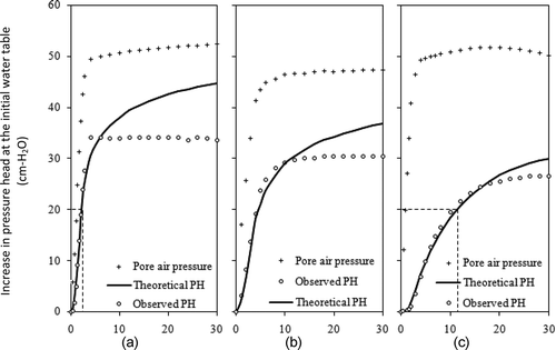
Figure 5. Theoretical and observed pressure head (PH) at the lower boundary of the zone of tension saturation (initial water table, βwt) as a result of (a) a lower and (b) higher, compressed pore air pressure imposed on the upper boundary of the zone of tension saturation in the Fine soil. Pressure head diffusivity coefficient, de, for the soil was 65 cm2 min−1.
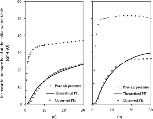
From , it can be seen that the overlap, or the agreement, between the theoretical results and the observed results becomes better with the increase of the fineness of the soil. This is as a result of the losses of potential energy from the system through groundwater discharge. In the Coarse soil, as soon as the experiment was started, there was an instantaneous and large discharge of groundwater from the system and this resulted in instantaneous losses from the system. The rate and amount of discharge of groundwater decreased with the fineness of the soil. Consequently, since the model was developed based on the principle of conservation of potential energy, it simulated more precisely the transient pressure head in the Fine soil, in which the loss in potential energy was low.
5. Conclusions and recommendations for further research
The rapid response of groundwater level (table) in the Lisse effect is a result of the introduction of additional pressure head (potential energy) into the saturated zone, below the upper boundary of the zone of tension saturation, by the compressed pore air pressure. The introduced pressure head is transmitted through pore water in the saturated zone by a diffusion mechanism, i.e., without water fluxes. The key material parameter that determines the transmission behaviour of the introduced pressure head is the newly proposed pressure head diffusivity coefficient. A high value of pressure head diffusivity coefficient indicates rapid transmission of pressure head and vice versa.
Acknowledgements
The study was hosted by the School of Engineering (SE, UKZN) in conjunction with the School of Agricultural, Earth and Environmental Sciences (SAEES, UKZN) and the Department of Soil, Crop and Climate Sciences at the University of the Free State (SCCS, UFS), South Africa. Mr J.J. Pretorius, a chief technician at SE and SAEES (UKZN), was very helpful in the design and implementation of the laboratory experiments. English language was edited by Sharon Rees of the SE, UKZN. We wish to thank the reviewers (Nachabe Mahmood and the anonymous reviewer) and the handling editor, Dr Xi Chen, for their valuable comments that helped us improve both the readability and the technical aspects of this article.
Disclosure statement
No potential conflict of interest was reported by the authors.
Additional information
Funding
References
- Brooks, R.H. and Corey, A.T., 1964. Hydraulic properties of porous media. Hydrology paper No. 3. Fort Collins, CO: Colorado State University.
- Brustkern, R.L. and Morel-Seytoux, H.J., 1970. Analytical treatment of two-phase infiltration. Journal of the Hydraulic Division Proceedings, ASCE, 96 (HY12), 2535–2548.
- Carslaw, H.S. and Jaeger, J.C., 1959. Conduction of heat in solids. New York, NY: Oxford University Press.
- Dixon, R.M. and Linden, D.R., 1972. Soil air pressure and water infiltration under border irrigation. Soil Science Society of American Journal, 36 (6), 948. doi:10.2136/sssaj1972.03615995003600060032x.
- Flury, M. and Gimmi, T., 2002. Solute diffusion. In: J.H. Dane, and G.C. Topp, eds. Methods of soil analysis. Part 4. Physical methods. Madison, WI: American Society of Agronomy, 1323–1351.
- Freeze, R.A. and Cherry, J.A., 1979. Groundwater. Englewood Cliffs, NJ: Prentice-Hall.
- Gee, G.W. and Bauder, J.W., 1986. Particle-size analysis. In: A. Klute, eds. Methods of soil analysis. Part 1. Physical and mineralogical methods. Madison, WI: American Society of Agronomy, 383–411.
- Gillham, R.W., 1984. The capillary fringe and its effect on water-table response. Journal of Hydrology, 67 (1–4), 307–324. doi:10.1016/0022-1694(84)90248-8.
- Guo, H., Jiao, J.J., and Weeks, E.P., 2008. Rain-induced subsurface airflow and Lisse effect. Water Resources Research, 44 (7), 136–144. doi:10.1029/2007WR006294.
- Heliotis, F.D. and DeWitt, C.B., 1987. Rapid water table responses to rainfall in a Northern Peatland ecosystem. Journal of the American Water Resources Association, 23 (6), 1011–1016. doi:10.1111/j.1752-1688.1987.tb00850.x.
- Ishihara, Y. and Shimojinia, E., 1983. A role of pore air in infiltration process. Bulletin of Disaster Prevention and Research Institute, 33 (4), 163–222.
- Janna, W.S., 1987. Introduction to fluid mechanics. Boston, MA: PWS Engineering.
- Kevorkian, J., 2000. Partial differential equations: analytical solution techniques. New York: Springer-Verlag New York.
- Klute, A., 1986. Water retention: laboratory methods. In: A. Klute, eds. Methods of soil analysis. Part 1. Physical and mineralogical methods. Madison, WI: American Society of Agronomy, 635–662.
- Klute, A. and Dirksen, C., 1986. Hydraulic conductivity and diffusivity: Laboratory methods. In: A. Klute, eds. Methods of soil analysis. Part 1. Physical and mineralogical methods. Madison, WI: American Society of Agronomy, 687–734.
- Linden, D.R. and Dixon, R.M., 1975. Water table position as affected by soil air pressure. Water Resources Research, 11 (1), 139–143. doi:10.1029/WR011i001p00139.
- McWhorter, D.B., 1971. Infiltration affected by flow of air. Hydrology paper No. 49. Fort Collins: Colo. State Univ. Fort Collins.
- Morel-Seytoux, H.J. and Khanji, J., 1975. Equation of infiltration with compression and counterflow effects / Equation dans le cas de l’infiltration avec l’effet de compression d’air et l’effet de contre-courant. Hydrological Sciences Bulletin, 20 (4), 505–517. doi:10.1080/02626667509491583.
- Peck, A.J., 1960. The water table as affected by atmospheric pressure. Journal of Geophysical Research, 65 (8), 2383–2388. doi:10.1029/JZ065i008p02383.
- Peck, A.J., 1965. Moisture profile development and air compression during water uptake by bounded porous bodies: 3. Vertical columns. Soil Science, 100 (1), 44–51. doi:10.1097/00010694-196507000-00007.
- Powers, W.L., 1934. Soil-water movement as affected by confined air. Journal of Agricultural Research, 49 (12), 1125–1134.
- Rasmussen, T.C., et al., 2000. Tracer vs. pressure wave velocities through unsaturated saprolite. Soil Science Society of American Journal, 64 (1), 75–85. doi:10.2136/sssaj2000.64175x.
- Touma, J., Vachaud, G., and Parlange, J.Y., 1984. Air and water flow in a sealed, ponded vertical soil column: experiment and model. Soil Science, 137 (3), 181–187. doi:10.1097/00010694-198403000-00008.
- Vachaud, G., Gaudet, J.P., and Kuraz, V., 1974. Air and water flow during ponded infiltration in a vertical bounded column of soil. Journal of Hydrology, 22 (1–2), 89–108. doi:10.1016/0022-1694(74)90098-5.
- Vachaud, G., et al., 1973. Effects of air pressure on water flow in an unsaturated stratified vertical column of sand. Water Resources Research, 9 (1), 160–173. doi:10.1029/WR009i001p00160.
- Wang, Z., et al., 1997. Two-phase flow infiltration equations accounting for air entrapment effects. Water Resources Research, 33 (12), 2759–2767. doi:10.1029/97WR01708.
- Wang, Z., et al., 1998. Air entrapment effects on infiltration rate and flow instability. Water Resources Research, 34 (2), 213–222. doi:10.1029/97WR02804.
- Waswa, G.W. 2013. Transient pressure waves in hillslopes. Thesis (PhD). School of Engineering, KwaZulu-Natal, Durban, South Africa. 120 pages.
- Waswa, G.W., et al., (2013). Transient pressure waves in the vadose zone and the rapid water table response. Vadose Zone Journal, doi:10.2136/vzj2012.0054.
- Weeks, E.P., 2002. The Lisse effect revisited. Ground Water, 40 (6), 652–656. doi:10.1111/j.1745-6584.2002.tb02552.x.
- Yunus, C.A., 2003. Heat transfer, A practical approach. New York, NY: Tata McGraw-Hill.
