Abstract
Introduction: This study compared simulated temperature distributions of intraluminal heating devices, concerning penetration and homogeneity. A hot water balloon, a 434-MHz monopole and a 915-MHz dipole antenna, both with incorporated cooling, and a 27-MHz applicator were investigated.
Methods: The hot water balloon had an inlet temperature of 45°C and a flow rate of 7.85 ml s−1. The cooling water and air had a temperature of 41°C and 37°C and a flow rate of 5.89 ml s−1 and 1.8 l s−1, respectively. A 27-MHz applicator consisting of one or two electrode(s) was modelled to demonstrate axial steering for inhomogeneous tissue properties. Calculated power distributions were scaled to a total power of 10 W in tissue before the corresponding temperature distributions were calculated.
Results: The hot water balloon and the 27-MHz device showed a thermal penetration depth of ∼4 and ∼10 mm, respectively. The penetration depths of the 434- and 915-MHz applicators were comparable: ∼10 and ∼16 mm with water and air cooling, respectively. With the 27-MHz applicator, spatial steering was applied to minimize temperature gradients along the applicator. The 434- and 915-MHz antennas have no steering possibilities. The temperature distribution of the hot water balloon is not affected by inhomogeneous dielectric properties, only slightly by inhomogeneous perfusion.
Conclusion: A hot water balloon is useful for heating tumours with a limited infiltration in tissue, while a 27-MHz device has the best potential to realize a homogeneous temperature distribution in larger tumours.
Introduction
Hyperthermia is heating of tumours in the range of 41–45°C, while preventing excessive heating of normal tissue. Clinical outcome is strongly correlated to the achieved thermal dose Citation[1–4]. Therefore, a sufficiently high and homogeneous steady state temperature in tumour tissue is important, but this is difficult to achieve in the clinic Citation[5–7].
Tumours located at an existing lumen or cavity, such as oesophagus, rectum, cervix uteri and bladder, are relatively easily accessible and therefore intraluminal or intracavitary heating techniques are a natural choice. A disadvantage of intraluminal hyperthermia devices is their small (thermal) penetration depth, i.e. the depth where the power or temperature is reduced to 1/e times the value at the surface of the applicator. The penetration depth of the absorbed power generally increases with decreasing frequency, but for intraluminal applicators the upper limit of the penetration depth is determined by the radius of the cavity. The depth where the absorbed power is reduced to half the value at the antenna surface is at most equal to the radius of the cavity Citation[8]. To achieve minimally required therapeutic temperature levels over the complete tumour volume, a high surface temperature will be necessary, which may induce thermo-toxicity.
To improve the effective thermal penetration depth of microwave applicators, and thereby the homogeneity of the temperature distribution, applicators with an incorporated water or air cooling system can be applied Citation[9–11]. Using active cooling, the maximum temperature will be shifted away from the applicator surface, so the surface temperature will not be a treatment-limiting factor and a larger volume can be heated to minimally required therapeutic levels.
Besides using microwave heating, tumours in a lumen or cavity can also be heated using a balloon with circulating hot water Citation[12], Citation[13] or a capacitive heating device Citation[14]. A hot water balloon is a relatively simple technique, which will generate a homogeneous heat radiation in axial direction, provided that the flow rate is high enough to maintain a constant water temperature, i.e. the temperature gradient of the water in axial direction is negligible Citation[15]. Capacitive heating techniques using electrodes allow for spatial steering in axial direction by using multiple electrode segments Citation[14]. The power delivered by the electrodes can be adjusted individually to compensate for inhomogeneities in tissue and/or perfusion.
In this study different intraluminal heating techniques were simulated and compared. The modelled geometry represented the oesophageal lumen surrounded by a block of tissue. The investigated heating techniques were a hot water balloon, a 434-MHz monopole antenna and a 915-MHz dipole antenna, both with incorporated water or air cooling, and a 27-MHz capacitive heating technique using electrodes. The penetration depths and the homogeneity of the temperature distributions were compared.
Methods
The heating ability of a hot water balloon, a 434-MHz monopole and 915-MHz dipole antenna with incorporated water or air cooling system and a 27-MHz capacitive heating technique were investigated. To calculate power and temperature distributions, the oesophagus was modelled as a cylinder of air with a diameter of 1 cm, surrounded by a block of homogeneous muscle tissue. The target volume to be heated was assumed 8 cm long. In clinical practice, an applicator should have an appropriate length to heat the tumour over its length. An average tumour length of 8 cm was assumed. Incorporating a clinical variation in tumour length complicates comparison between these heating devices. Therefore, a target volume of 8 cm was assumed in this study and all modelled applicators had a length of 8 cm. Note that in the simulations no tumour was modelled, since this would incorporate additional independent parameters. When a tumour is modelled, its parameters (tumour size, thermal and dielectric properties) can vary and this natural variation should then be reflected in the analysis. This analysis would be complicated, since specific tumour properties, such as a certain tumour volume, might favour one applicator over other types. To explore exclusively the differences between various intraluminal applicators, it is appropriate to model homogeneous tissue. All simulations were performed at a resolution of 0.5 × 0.5 × 1.0 mm3; see sections below for the modelling of the various applicators in more detail.
Hot water balloon
A hot water balloon with a diameter of 1 cm and a length of 8 cm was modelled. For patient safety, the temperature in the target volume is generally not allowed to exceed 45°C. The water had an inlet temperature of 45°C and a flow velocity of 10.0 cm s−1, which corresponds to a flow rate of 7.85 ml s−1. The total computational volume was 6 × 6 × 12 cm3. The outer boundaries of the computational domain were kept at a constant temperature of 37°C.
434-MHz monopole and 915-MHz dipole
434-MHz monopole
The modelled 434-MHz monopole antenna is a coaxial cable shortened at one end. It consisted of an inner conductor, dielectric insulation and an outer conductor with a diameter of 1, 3 and 5 mm, respectively. The antenna had a ring aperture of 2 mm in the external cable, which corresponds to two voxels in axial direction. The radiating monopole is the outer surface of the applicator from the ring aperture to the shortened end. An electromagnetic field is generated by the currents flowing on the monopole surface and on the external surface of the coaxial cable feeding the monopole.
The optimal antenna length (i.e. the resonance length) in muscle tissue was predicted from the electromagnetic field theory of insulated antennas in conducting or dielectric media Citation[16]. The optimal length for a quarter-wave monopole at 434 MHz was predicted to be ∼7 cm. The theoretical model used Citation[16] has three regions—inner conductor, insulator and tissue—so the outer conductor was not taken into account and the resonance length for the applicator modelled in this study might be slightly different from the one predicted by the model in Citation[16]. The predicted resonance length should be interpreted as an indication of the optimal antenna length. A monopole of 8 cm was modelled, which is close to the theoretical resonance length and is thus expected to perform well.
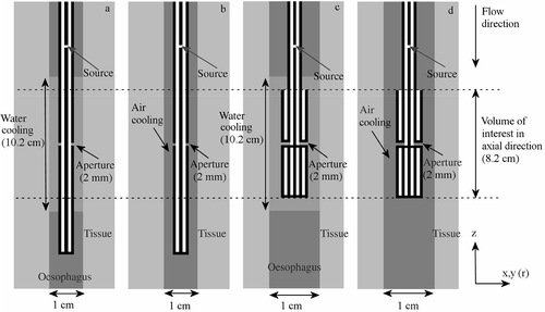
show a schematic representation of the modelled water-cooled and air-cooled monopole antenna. The volume of interest in axial direction extends 4 cm below and 4 cm above the aperture and is also indicated in this picture. A section of 10.2 cm (5 cm above and 5 cm below the aperture) was cooled with distilled water at 41°C with a flow velocity of 10.0 cm s−1, which corresponds to a flow rate of 5.89 ml s−1. Air cooling was applied over the complete length of the modelled oesophagus with air of 37°C flowing at 30.0 m s−1, or 1.8 l s−1 in the target region. The flow direction in the simulations was from top to bottom (i.e. annulus-first flow).
Figure 1. Schematic representation of the modelled water-cooled and air-cooled monopole antenna ((a) and (b)) and the coaxial dipole antenna ((c) and (d)). In the case of air cooling, the cooled section reached over the complete length of the modelled oesophagus ((b) and (d)). These longitudinal cross sections are not to scale.
915-MHz dipole
Since the resonance length at 915 MHz is about half the resonance length at 434 MHz, a half-wave dipole antenna was modelled. The dipole was symmetric and consisted of two sections of 4 cm (i.e. approximately a quarter wavelength) with an aperture of 2 mm. The dipole antenna was modelled as a coaxial antenna, which is defined as ‘an antenna comprised of an extension to the inner conductor of a coaxial line and a radiating sleeve which in effect is formed by folding back the outer conductor of the coaxial line’ Citation[17]. The diameters were 1, 2.5, 3, 4 and 5 mm for the inner conductor, first dielectric layer, outer conductor, second dielectric layer and the back-folded outer conductor, respectively.
show axial cross sections of the modelled coaxial dipole antennas. The water-cooled section was 10.2 cm long and reached 1 cm beyond the proximal and distal end of the dipole. The water had a flow velocity of 10.0 cm s−1, which corresponds to 5.89 ml s−1 over the length of the dipole and an inlet temperature of 41°C. As for the monopole antenna, air cooling was performed over the complete length of the modelled oesophagus with air at 37°C and a flow velocity of 30.0 m s−1, corresponding to 1.8 l s−1 over the length of the dipole.
The E-Field distributions were calculated with our voxel-based treatment planning system using the finite difference time domain (FDTD) method to solve Maxwell's equations Citation[18]. The FDTD method has been validated earlier using analytical solutions Citation[19]. The implemented computer code has been validated using analytical solutions. Furthermore, calculated and measured E-Field distributions in tissue-equivalent phantoms have been compared for a specific clinical setup Citation[18], Citation[20]. Deviations between simulations and measurements were in the same order of magnitude as the measurement accuracy. The coaxial source point was positioned in a ‘gap’ in the inner conductor () and excited by means of a triple cosine pulse.
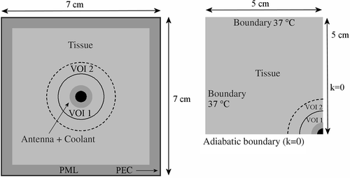
At a large distance from the applicator the E-Field will be zero. Using zero E-Field as a boundary condition, a very large computational domain would be necessary to avoid reflections in the volume of interest. To avoid reflections when using a smaller, manageable computational domain, several types of absorbing boundary conditions have been proposed in literature Citation[21–24]. Absorbing boundary conditions aim to absorb the electric field as if the domain were not truncated. A perfectly matched layer is the most effective boundary condition and was designed to absorb without reflections of the electromagnetic waves Citation[21]. In this study, a nearly perfectly matched layer Citation[25] was implemented, which performs identically to the standard perfectly matched layer Citation[26]. The volume of the computational domain was 7 × 7 × 22 cm3, including 10 layers for absorbing boundary and a perfect electric conductor (E = 0 inside the perfect electric conductor and the tangential field Etang = 0 at the surface) at all sides. The computational volume was chosen such that the SAR beyond the computed distribution (i.e. the volume excluding the absorbing boundary layers) is negligible. However, the thermal penetration depth will be larger than the SAR penetration depth, since active cooling is applied. Therefore, this volume was extended in the xy-direction to 10 cm with SAR values of 0 in order to set an appropriate 37°C boundary condition for temperature calculations. shows transversal cross sections of the computational domain applied for E-Field (left) and thermal (right) computations. Because of cylindrical symmetry of the geometry, the resulting temperature distribution will also be cylindrical symmetric. Temperature values at both sides of a plane of symmetry should be equal, which implies a zero derivative, i.e. no heat will pass through the plane of symmetry. To reduce the computation time, only one quarter of the total volume was simulated for thermal computations, applying adiabatic boundary conditions (i.e. no heat transfer, k = 0) at the planes of symmetry. The annular volumes of interest VOI 1 and VOI 2, with an outer radius of 1 and 1.5 cm respectively, are used later on for analysis of the temperature distributions.
27-MHz capacitive heating
Heating at 27 MHz is based on capacitive coupling Citation[27], Citation[28], such as in the multi-electrode current source (MECS) interstitial hyperthermia system Citation[14], Citation[27], Citation[29]. This method is a variation on the local current field method, i.e. resistive heating by means of currents passing between different pairs of electrodes or between electrodes and an external ground plane. The electrodes are inserted in loss-less implant catheters. The catheter acts as a dielectric between the electrode and tissue, forming a capacitor. The electrode acts like a current source, since the impedance across the catheter is large compared with the tissue impedance Citation[30]. The length of the electrode(s) is not critical; any applicator length can be constructed, making this type of heating very flexible. The applicator consists of a catheter, covered partly by conducting paint at the electrode locations. A conductor inside the catheter connects each electrode to a coaxial cable, which connects the electrode to the generator system. Energy transfer from electrode to tissue is only effective over the painted area (i.e. the electrode surface) Citation[30]. The concept of capacitive heating with electrodes can also be used to develop an intraluminal multi-electrode current source heating system.
Because the volume of interest is relatively small compared with the wavelength of 27 MHz in tissue (∼1 m in muscle tissue Citation[31]), a quasi-static approximation of Maxwell's equations was used. At the University Medical Center Utrecht, a sophisticated application has been developed to calculate the power distribution due to one or more current source applicators, which makes use of the quasi-static approximation of Maxwell's equation Citation[32]. This application has been verified using analytical solutions Citation[32] and was used to calculate the power distribution.
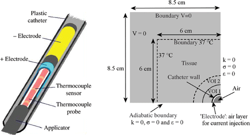
One electrode segment of 8 cm was modelled in a closed-end polyethylene catheter with an inner and outer diameter of 0.9 and 1 cm, respectively. An air gap of 0.5 cm was modelled between the electrode and the closed end of the catheter. The open end of the catheter was located 1 cm from the proximal end of the electrode. A current source electrode can be described geometrically as a tube with a constant current density normal to its surface. The hollow electrode was discretized and the total current of the electrode was distributed evenly over all its associated nodes. This corresponds to a current injection in the ‘air’ layer next to the catheter wall. The current is injected in discrete points at the centre of these nodes Citation[32]. For temperature calculations the total power will be scaled, so the total current is scaled accordingly. The total volume was 17 × 17 × 17 cm3, with boundary condition V = 0. Because of cylindrical symmetry of the geometry, again only one quarter of the total volume was simulated, applying adiabatic boundary conditions (σ = 0, ε = 0 and k = 0) at the planes of symmetry. For temperature calculations the total volume was cropped to 12 × 12 × 17 cm3.
The left-hand side of shows a picture of an interstitial MECS applicator, which consists in this case of two hollow electrodes in a catheter. The right-hand side of shows the computational domain used for power and temperature calculations and shows schematically how a current source applicator was modelled.
Inhomogeneous tissue properties
Inhomogeneities in tissue can occur in dielectric properties and perfusion and will affect the temperature distribution induced by the applicators. Inhomogeneities in dielectric properties will have no influence on the heating pattern of a hot water balloon. However, inhomogeneities in dielectric properties will often imply differences in thermal properties, of which the perfusion is the most important factor for the achieved temperature distribution. The 27-MHz device can consist of multiple electrode segments, which allows axial steering. In view of this, inhomogeneous tissue properties were studied for the hot water balloon and the 27-MHz device. The computational volume was divided in two equal parts. The lower half of the volume had lower dielectric properties (σ = 0.5 S m−1 and ε = 75) and a lower perfusion (Wb = 2.22 kg m−3°C−1), compared with the upper half (σ = 0.71 S m−1, ε = 102 and Wb = 5 kg m−3°C−1). The single electrode segment was replaced by two electrodes of 3.8 cm, with a gap of 5 mm in between.
Temperature calculations
Temperature distributions were calculated by solving the bio heat transfer equation Citation[33]:with ct the specific heat capacity (J kg−1°C−1) and ρt the tissue density (kg m−3). The term ∇ · (kt ∇ T) represents the heat conduction in tissue, with kt (W m−1°C−1) the thermal conductivity of tissue. The second term on the right represents the perfusion, with cb the specific heat of blood, Wb (kg m−3 s−1) the volumetric perfusion rate and Tart the local arterial or body core temperature (37°C). The power density added by the heating device is represented by P (W m−3). The calculated power distributions were scaled to 10 W in the modelled tissue volume. Temperature distributions were calculated at steady state. The dielectric and thermal properties used for the simulations are summarized in Citation[34], Citation[35].
Table I. The dielectric and thermal properties used in the simulations; conductivity (σ (S m−1)), relative permittivity (ε (−)), density (ρ (kg m−3)), specific heat capacity (c (J kg−1°C−1)) and thermal conductivity (k (W m−1°C−1)).
For the air-cooled applicators the domain had to be enlarged in axial direction (the upper boundary in ) to set an appropriate boundary condition of 37°C. As a workaround, the domain was virtually enlarged by applying a thermal conductivity kt = 0.01 W m−1°C−1 to the muscle tissue of this transversal boundary plane.
For all simulations, a perfusion rate of 5 kg m−3 s−1 was applied, which corresponds to 30 ml 100 gr−1 min−1. For the above-described demonstration of axial steering at 27 MHz, the lower part of the volume had a perfusion of 2.22 kg m−3 s−1 and the total power for two electrodes was scaled to 6.5 W to avoid temperatures exceeding 45°C. Since the anatomy exhibits cylindrical symmetry, only one quarter of the total volume was simulated to calculate temperatures, applying adiabatic boundary conditions at the planes of symmetry.
Active cooling. Heat transfer to the circulating water or air was modelled using the heat flux relation:where ∂/∂n denotes the derivative in the direction of the outward normal to the surface, which is the radial direction in this case, T is the tissue temperature at the oesophageal wall, Tcool is the local temperature of the flowing water or air and H (W m−2°C−1) is the heat transfer coefficient. The Reynolds number (Re) is defined as
where v (m s−1) is the mean flow velocity, ρ (kg m−3) is the density of the cooling medium and η (kg m−1 s−1) is the viscosity. For water at 41 and 45°C a viscosity of 6.53 × 10⁻⁴ and 5.97 × 10⁻⁴ kg m−1 s−1 was used, respectively. Air at 37°C had a viscosity of 1.867 × 10⁻⁵ kg m−1 s−1 (http://www.engineeringtoolbox.com/). The hydraulic diameter is represented by Dh (m). For a tube Dh is simply the diameter of the tube and for an annulus Dh is defined as Dh = 2(ro − ri), where ri and ro are the inner and outer radius of the annulus, respectively. Flow is laminar for Reynolds numbers <2300 and turbulent for Re > 2300. The Nusselt number (Nu) is related to the heat transfer coefficient using
with k (W m−1°C−1) the thermal conductivity of water or air.
When the flow has a completely developed temperature profile as well as a fully developed velocity profile, the heat transfer between tissue and the circulating air or water can be treated as constant. At high flow rates as applied in this study, the temperature profile near the entrance is not yet fully developed. For turbulent flow, as applied for air cooling, the entry length is much shorter than for laminar flow. Therefore, for turbulent flow entrance effects were ignored and a constant Nusselt number was applied over the complete cooling length. In an applicator with integrated cooling, the coolant flows through a concentric annulus. The Nusselt number for turbulent flow in a concentric annulus is given by Citation[36]:where Di and Do are the inner and outer diameter of the annulus, respectively. The value of Nutube is given by Citation[37]:
In equation z6, Pr is the Prandtl number: Pr = ηc/k, with c (J kg−1°C−1) the specific heat capacity of the coolant and Re is the Reynolds number from equation 3. The complete cooling length was considered a concentric annulus with Di = 0.005 m and Do = 0.01 m.
For laminar flow, as applied for water cooling, thermal entrance effects were taken into account by calculating the local Nusselt number as a function of the axial position Citation[38]. A fully developed velocity profile can be assumed for water since Pr > 1, so the velocity profile develops faster than the temperature profile Citation[39]. For the hot water balloon local Nusselt numbers were calculated using the theory described by Kays and Crawford Citation[39]. Entrance effects of laminar flow through an annulus have been described in great detail by Lundberg et al. Citation[40]. In this study the heat flux over the outer wall was assumed constant and the inner wall was treated as insulated.
The heat exchange between the cooling medium and tissue was implemented using a separate tissue and balloon space, similar to the implementation of discrete vessels described by Kotte et al. Citation[41]. To avoid underestimation of the lumen wall temperature, heat exchange between balloon and tissue only takes place at the wall of the balloon, in outward radial direction. Each time step, the temperature profile of the coolant was shifted axially to mimic fluid flow Citation[41].
Comparison of SAR and temperature distributions
The treatment-planning software used at our department uses Cartesian coordinates. From the 3D Cartesian SAR and temperature distributions, an average radial profile was determined at each axial location. This results in a longitudinal cylindrical symmetrical cross section. The penetration depth of the absorbed power was compared for the different radiating antennas. Furthermore, the thermal penetration depths were compared for all intraluminal devices, as well as the homogeneity of the temperature distribution. The penetration depth was defined as the depth where the SAR or temperature rise is reduced to 1/e times the maximum SAR or temperature rise. The homogeneity of the temperature distribution was examined by the axial temperature profile over the tissue voxels next to the lumen and by the overall temperature heterogeneity coefficient (HC), which is defined as Citation[42]:where Tart is the local arterial temperature (37°C) and T10 and T90 are the temperature at least achieved in 10% and 90% of the target volume, respectively. This heterogeneity coefficient is an indication of the heterogeneity, relative to the T90 achieved; a high HC implies a heterogenous temperature distribution. The heterogeneity coefficient was determined over an annulus around the oesophagus with an inner radius of 0.5 cm and an outer radius of 1 and 1.5 cm. This annulus extended 4 cm above and below the aperture of the 434- and 915-MHz antennas and over the complete length of the hot water balloon and 27-MHz electrode(s). See also for the definition of these volumes of interest.
Results
The SAR and temperature distributions resulting from the different intraluminal applicators were examined. The radial position r = 0.5 cm corresponded to the lumen wall. The axial position z = 0 corresponded to the location of the aperture of the 434 and 915-MHz antennas and to the centre of the hot water balloon and the 27-MHz applicator.
SAR distributions
The radial SAR profiles at z = 0 are shown in . The corresponding penetration depths are listed in . The penetration depths of 434 and 915 MHz were approximately equal. Air cooling provided a much larger SAR penetration depth than water cooling. The maximum SAR near the aperture was much higher with water cooling, but the decay was much slower when air cooling was applied. shows the axial SAR profiles over the first tissue voxels, directly next to the applicator. This figure shows that using air cooling the SAR is more extended in axial direction along the proximal part of the oesophagus, while the SAR was more concentrated around the target area when water cooling was applied.
Figure 4. Radial (a) and axial (b) SAR profiles of the different intraluminal heating devices. Radial profiles were determined at z = 0 and axial profiles were determined over the first tissue voxels next to the applicator. In the connector is located at the right-hand side.
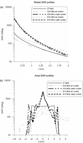
Table II. SAR and thermal penetration depths at z = 0 of the different intraluminal heating devices.
Temperature distributions
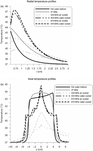
shows the radial temperature profiles at z = 0. This graph shows that the thermal penetration of the microwave antennas was improved using active cooling by shifting the temperature maximum away from the oesophageal wall. The thermal penetration depths were determined from these curves and are listed in . The SAR penetration depth was smaller for water-cooled antennas compared with air-cooled antennas, which was also reflected in the thermal penetration depth. shows the axial temperature profiles next to the applicator. The hot water balloon and 27-MHz current source applicator showed the most uniform temperature profile in axial direction. A slightly larger temperature rise (∼1°C) can be observed at the proximal end (i.e. the entrance region) of the hot water balloon, compared with the distal end. This is remarkable since the temperature drop of the circulating water was negligible (0.084°C) over this length. The larger temperature difference in the neighbouring tissue can be explained by the variation in Nusselt numbers over this length. The Nusselt numbers are much larger at the entrance region, which implies a better heat transfer to tissue. Air-cooled microwave applicators showed a more extended heating pattern in the proximal axial direction than water-cooled applicators.
Figure 5. Radial (a) and axial (b) temperature profiles of the different intraluminal heating devices. Radial profiles were determined at z = 0 and axial profiles were determined over the first tissue voxels next to the applicator.
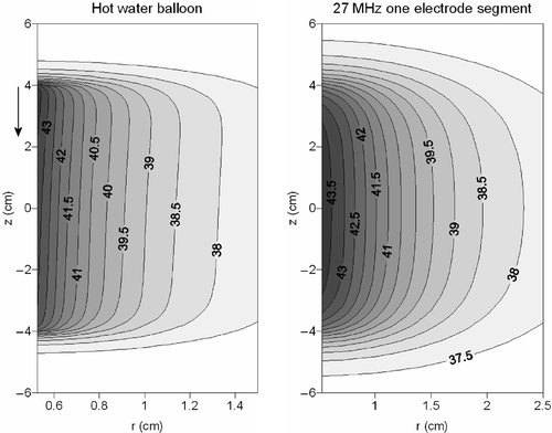
shows contour plots in the longitudinal cross section of the temperature distribution resulting from the hot water balloon and the 27-MHz current source applicator. The heating patterns appeared rather similar, but the 27-MHz device yielded more curved contours and a larger penetration depth than a hot water balloon.
Figure 6. Contour plots of the temperature distribution resulting from a hot water balloon (left) and a 27-MHz current source applicator consisting of one electrode segment (right). The flow direction in the hot water balloon is indicated with an arrow.
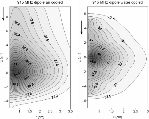
and show contour plots of the temperature distribution resulting from the water- and air-cooled 434-MHz monopole antenna and the 915-MHz dipole antenna. These two figures show in more detail the extended heating in axial direction when air cooling is applied. In the case of water cooling, the heating pattern is more concentrated to the target area. The achieved maximum temperature is higher using water cooling, albeit with a smaller penetration depth. This can be explained by the high permittivity of water, providing a good dielectric coupling of fields to tissue and the low permittivity of air, which provides a poor coupling (see Discussion). The cooling water of the cooled monopole and dipole antenna showed a maximum temperature rise of 0.066 and 0.07°C, respectively. Cooling air showed a maximum temperature rise of 0.39 and 0.44°C, for the monopole and dipole applicator respectively.
Figure 7. Contour plots of the temperature distribution resulting from a 434-MHz air-cooled (left) and water-cooled (right) coaxial monopole antenna. The flow direction is indicated with an arrow.
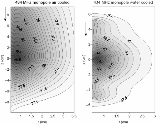
Figure 8. Contour plots of the temperature distribution resulting from a 915-MHz air-cooled (left) and water-cooled (right) coaxial dipole antenna. The flow direction is indicated with an arrow.
Inhomogeneous tissue properties
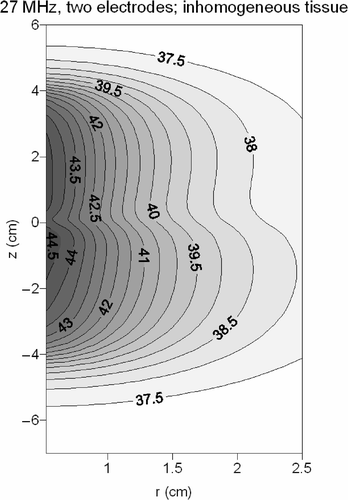
shows the temperature distribution in inhomogeneous tissue resulting from a hot water balloon and a 27-MHz current source applicator consisting of a single electrode. The upper and lower part of the volume had different dielectric properties and a perfusion rate of 5 and 2.22 kg m−3 s−1, respectively. For the hot water balloon, the temperature profiles in axial direction were still rather homogeneous. Despite the large heterogeneity in perfusion rate, a relatively small heterogeneity was observed in the temperature profiles. Far more heterogeneous temperature profiles were achieved for the single electrode 27-MHz device. The temperatures in the lower part of the volume were significantly higher.
Figure 9. Contour plots of the temperature distribution in inhomogeneous tissue resulting from a hot water balloon (left) and a 27 MHz current source device (right). The flow direction in the hot water balloon is indicated with an arrow.
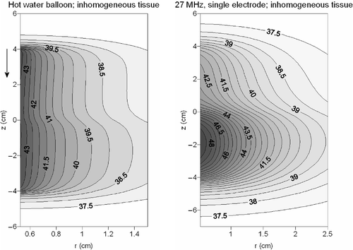
The homogeneity of the temperature distribution can be improved by using two independent electrodes. shows the temperature distribution when two electrodes were used with current amplitudes 1:0.66, resulting in more homogeneous heating along the applicator. Power was scaled to 6.5 W in this case.
Heterogeneity coefficients
The overall heterogeneity coefficients (HC) were determined for all calculated temperature distributions over an annulus around the oesophagus with an inner radius of 0.5 cm and an outer radius of 1 and 1.5 cm. Results are shown in .
Table III. Temperatures (T90 and T10) and the heterogeneity coefficient (HC) determined over an annulus around the oesophagus with an inner radius of 0.5 cm and an outer radius of and 1 and 1.5 cm. This annulus reached 4 cm above and below the aperture of the 434- and 915-MHz antennas and over the complete length of the hot water balloon and 27-MHz device.
The highest HC in the small annulus, i.e. the most heterogeneous temperature distribution, was achieved with the air-cooled 915-MHz dipole. This is due to the relatively large area around the lower part of the dipole, in which a very low temperature was achieved (cold tip). The water-cooled dipole yielded a more symmetric heating pattern, resulting in a lower HC. The 434-MHz air-cooled monopole antenna on the other hand, showed a rather good HC (HC = 0.8 in the small annulus), but the achieved temperatures were rather low. Besides homogeneity of the temperature distribution, achieving sufficiently high temperatures is also important. Consequently, a larger amount of power will be necessary for more adequate heating. For 434 MHz the temperature distribution became less uniform with water cooling. The hot water balloon showed a rather homogenous temperature profile in axial direction (). However, a relatively large HC (HC = 1.7 in the small annulus) was observed, owing to the very small thermal penetration depth. This value is not very bad compared with those for the microwave antennas, but the values for the annulus with an outer radius of 1.5 cm clearly show that the small penetration depth is the limiting factor to achieve a homogeneous temperature distribution in larger tumours, when using a hot water balloon. For the air-cooled applicators the heterogeneity coefficient is approximately equal for both annuli. The 27-MHz device had a larger penetration depth compared to the hot water balloon and showed the lowest HC in homogeneous tissue.
In the case of inhomogeneous tissue, the heterogeneity coefficient became much higher with a single 27-MHz electrode, but using two independent electrodes with different current amplitudes a more homogeneous temperature distribution could be achieved, with an HC comparable to the case of homogeneous tissue. A hot water balloon in heterogeneous tissue showed a slightly better HC compared with the homogeneous case. Owing to the lower perfusion rate in the lower half of the volume the penetration depth is slightly larger, which is reflected in the T10 and T90.
Discussion
In this study, numerical simulations were performed to compare the SAR and temperature distributions of different intraluminal heating techniques, regarding penetration depth and homogeneity of the temperature distribution. The modelled geometry represented the oesophagus surrounded by a block of tissue, but the results will be valid for other intraluminal/intracavitary tumour sites as well. A hot water balloon, a 434-MHz monopole, a 915-MHz dipole and a 27-MHz current source applicator were investigated. Incorporated water or air cooling was modelled to improve the thermal penetration depth of the microwave antennas. The monopole and dipole antennas were assumed to be constructed from a coaxial cable. There are several possibilities for designing a monopole or a dipole antenna, and a different design of the antennas could lead to different radiation patterns, so the results of this comparative study cannot be generalized directly to other antennas. However, properties as penetration depth and differences between water and air cooling will be valid for other antenna designs as well.
The performance of the microwave antennas depends on both the resonance length and proper impedance matching of the antenna to the generator system. The insertion depth of the microwave antennas generally has an impact on the reflection coefficient as well. In this case, however, oesophageal tumours are heated and the applicator and a large part of the coaxial feeding cable are inserted in the oesophagus. The total inserted length will generally be about 40 cm, so there is no tissue–air interface near the region of interest in contrast with interstitial hyperthermia. Thus, for the situation examined in this paper, the reflection coefficient will mainly be determined by the length of the coaxial cable, which connects the applicator to the generator system.
The resonance length is the length at which the antenna performs optimally for the applied frequency. In this study, the resonance length of the microwave applicators was determined using an analytical solution, which served as an estimate. The length of the modelled antennas was close to this theoretical length. An antenna can also be expected to perform well when designed slightly shorter or larger than the true optimal length. This is not the case if the antenna is completely off resonance.
Matching of the antenna to the generator system is not relevant for the simulations presented in this study. The purpose of this study was to compare the general behaviour of several antennas, in terms of penetration depth and homogeneity of the temperature distribution. A nearly perfectly matched layer absorbing boundary condition was used to truncate the computational domain and the actual length of the coaxial cable was not incorporated in the simulations. This boundary condition was designed to absorb without reflection of the electromagnetic waves. In clinical practice impedance matching is important to minimize reflections over the coaxial cable. It provides a greater efficiency in power output, but does not alter the electromagnetic field and heating properties of the antennas as calculated in this study.
In general, the penetration depth decreases with increasing frequency. However, for cylindrical applicators the penetration depth is limited by the radius of the antenna Citation[8]. This explains why almost no difference in penetration depth is observed between a 434-MHz monopole and a 915-MHz dipole antenna in this study. A higher frequency yields a higher SAR at the surface of the applicator on account of the higher electrical conductivity, but with a comparable decay.
In spite of the small SAR penetration depth of intraluminal microwave techniques, a larger thermal penetration depth can be achieved when cooling of the antenna surface is applied, since the temperature maximum is shifted deeper into the tissue. Water cooling is more efficient than air cooling since the specific heat capacity and density are much higher and therefore water requires a lower flow rate to establish the same cooling rate as air. In this study, with the same power scaling, water cooling is found to yield a higher SAR and temperature in the region of interest near the lumen than air cooling, albeit with a smaller penetration depth.
Water provides more effective coupling of fields to tissue owing to the high permittivity of water. This can be derived from the condition that the normal electric flux (εE) should be continuous at the water–tissue or air–tissue interface. With less efficient coupling to tissue, the electric field will also propagate in axial direction, as can be observed in case of air cooling. Thus, as a result of efficient coupling the SAR pattern will be more concentrated to the target area in the case of water cooling. In the case of air cooling, the inefficient coupling results in a line source-like behaviour rather than a point source-like behaviour. This explains the larger penetration depth with air cooling.
shows a symmetric axial profile for the 27-MHz applicator, since this geometry is symmetric. The axial SAR profiles of the microwave applicators are asymmetric, but water-cooled applicators show a more symmetric profile than air-cooled applicators. Initially, a symmetric axial SAR profile might be expected for a symmetric dipole antenna. However, because of the coaxial feeding cable connected to the microwave antennas, the geometry becomes asymmetric and thus SAR profiles in are asymmetric.
The hot water balloon shows a homogenous heat radiation in axial direction, but owing to the small penetration depth the heterogeneity coefficient of the temperature distribution is relatively large. The 27-MHz device also has a homogenous temperature profile in axial direction and the penetration depth is better than for the hot water balloon, so a low heterogeneity coefficient is obtained. Axial steering is possible with this device so a relatively homogeneous temperature distribution can be maintained in case of inhomogeneous dielectric and thermal properties. In this example, two segments of 4 cm were used, but steering with this device is possible at centimetre scale, so more than two segments are also possible. The temperature distribution of a hot water balloon is not affected by inhomogeneities in dielectric properties. However, inhomogeneities in dielectric properties will often imply differences in thermal properties, of which perfusion is the most important factor. A large inhomogeneity in perfusion results in a relatively small heterogeneity in the temperature profile in axial direction, which makes this device rather robust.
For the 434-MHz monopole, air cooling results in a more homogeneous temperature distribution than water cooling. For the 915-MHz dipole on the other hand, the temperature distribution induced by the water-cooled antenna is more homogeneous. Since the aperture is in the centre of the target volume, the cold tip of the antenna is in the volume of interest when a dipole is used. Using a monopole of 8 cm, the cold tip is outside the volume of interest. With water cooling, the temperature at the tip of the dipole is elevated. Therefore, air cooling seems better for a monopole antenna, while water cooling seems more favourable for a dipole applicator, provided that the aperture is located in the centre of the target volume.
The temperature at the antenna tip can also be elevated by using more advanced air cooling. Using a flow channel which cools the proximal end with full effect and leaves the distal end uncooled, the small temperature elevation at the applicator tip will not be erased by the surface cooling Citation[43]. Such an advanced cooling technique can be used to improve the homogeneity of the temperature distribution, but the microwave devices lack axial steering, so in case of inhomogeneous tissue properties it will be very difficult to create a temperature distribution with a low heterogeneity coefficient. In theory, it would be possible to design a microwave antenna consisting of more segments and thereby allowing some axial steering. However, a major advantage of the 27-MHz current source applicator is that it is possible to use very small elements (∼1 cm), which allows steering at an extremely small scale.
Several previous studies preferred air cooling to water cooling Citation[9], Citation[10], Citation[44], since air cooling is easier to establish and yields a better thermal penetration and sufficient tumour cooling. In this paper, annulus-first flow (i.e. top to bottom) was modelled, but in clinical practice tube-first flow (i.e. bottom to top) will yield a greater symmetry in the tissue cooling rate Citation[9] and will thus result in a more favourable temperature distribution compared with annulus-first flow. The tissue cooling rate q′tis (W m−1) can be calculated by q′tis = πDoH(Twall − Tair), with Twall the local temperature at the oesophageal wall and Tair the air temperature. In this paper, the heat transfer coefficient is assumed constant for turbulent flow and the simulated temperature rise of the circulating air is less than 0.5°C, so for these simulations tube-first flow will yield minor differences in the achieved temperature distributions.
In the case of air cooling with turbulent flow, the Nusselt number is assumed constant over the complete length, since the thermal entry length is much shorter than for laminar flow. The annulus has an inner and outer diameter of 0.5 cm and 1 cm in the target volume, respectively. The annulus of the dipole antenna is slightly larger before the cooling air reaches the target region (see ) and at the end of the monopole and dipole antennas, the air flow enters a tube section. A flow velocity of 30 m s−1 in the target region corresponds to a volume flow of 1.8 10−3 m3 s−1 and yields a heat transfer coefficient of 141 W m−2°C−1. This volume flow will enter the larger annulus section with a velocity of 24.7 m s−1, which implies a heat transfer coefficient of 116 W m−2°C−1. When the air flow reaches the tube section the flow velocity will be reduced to 22.5 m s−1, which yields a heat transfer coefficient of 107 W m−2°C−1. These local heat transfer coefficients are about 20% lower than the value of 141 W m−2°C−1 used for the annulus in the target region. In the transitional regions, there will be a certain entrance length for the velocity profile to adapt fully to the new geometry, so, for example, in the transitional region from annulus to tube the heat transfer coefficient will be slightly larger than 107 W m−2°C−1. Furthermore, these regions are outside the target region, so it seems justified to assume a constant value for this heat transfer coefficient.
The resulting temperature distribution from the hot water balloon and the microwave antennas with integrated cooling is dependent on the inlet temperature and the flow velocity Citation[9], Citation[10]. Cooling will be optimal when the axial temperature gradient of the coolant is negligible. In these simulations the temperature gradients are smaller than 0.5°C, so the coolant temperature remains nearly constant and thus the flow velocity was chosen appropriately. The inlet temperature was chosen such that the wall temperature was in the therapeutic range for hyperthermia treatments. A lower inlet temperature for air cooling will improve the tumour cooling rate, but will also yield a lower tissue temperature at the lumen wall. show that the inlet temperatures are a reasonable choice. The water-cooled applicators show a maximum tissue temperature slightly exceeding the maximum acceptable temperature of 45°C. This can be compensated by applying a slightly lower amount of power; the lumen wall temperature is in the clinical therapeutic range. In the clinic, only temperature information of the lumen wall will generally be available so the maximum temperature remains unknown using applicators with integrated cooling. This maximum temperature can be estimated using the measured lumen wall temperature Citation[38].
Owing to the large relative permittivity of water, a water-cooled antenna tends to behave as a bare antenna Citation[10], which is also surrounded by material with a high permittivity. Air, on the other hand, has a very low relative permittivity. It has been shown that a bare antenna has a lower radial penetration than an insulated antenna Citation[45]. With less efficient coupling to tissue, the electric field will also propagate in axial direction. Thus, despite the better coupling of fields to tissue using a high permittivity coolant, a low permittivity is more beneficial for the penetration depth. Another possibility for cooling of the antenna surface would be to apply some kind of oil. Oil has a low permittivity and conductivity and a relatively high density and specific heat capacity, resulting in a better penetration than water cooling and more effective cooling than using air. Despite sophisticated cooling techniques for intraluminal microwave applicators, the lack of axial steering of these devices remains a drawback.
Conclusion
A hot water balloon and a 27-MHz current source applicator yield the most uniform heat radiation in axial direction. For superficial tumours with a penetration up to a few millimetres, a hot water balloon will generally be sufficient. In view of the thermal penetration depth, the temperature profiles and the heterogeneity of the temperature distributions, a 27-MHz device will preferably be used for heating of non-superficial tumours. A 434-MHz monopole antenna with integrated air cooling may also be appropriate, but a major advantage of the 27-MHz current source device is the possibility of spatial steering by using multiple segments. The penetration depth is relatively good and a 27-MHz multiple electrode applicator is an appropriate choice in view of the difficulties with axial steering when using microwave devices.
Further research and application
Intraluminal heating techniques alone are probably insufficient for adequate tumour heating. Since tumours can penetrate up to a few centimetres in the surrounding tissue, the radial penetration depth of intraluminal applicators will be a practical limitation for larger tumours. Regional hyperthermia provides more homogeneous tumour temperatures, but tumour temperatures often remain below the desired 43°C because of treatment limiting hot spots in normal tissue, particularly during hyperthermia treatments of patients with oesophageal cancer Citation[46]. A combination of intraluminal and external heating is expected to yield higher temperatures than with external heating alone and a more homogeneous temperature distribution than with intraluminal heating alone. At the Academic Medical Center, University of Amsterdam, combination of intraluminal devices with the locoregional 70 MHz AMC-4 waveguide system is planned. This is subject of current research at our institute Citation[47]. The clinical value of a hot water balloon combined with locoregional hyperthermia is under investigation. In view of the results of this study, an intraluminal 27-MHz device will also be developed and tested in the near future.
Acknowledgements
The authors thank Dr S. A. Cummer from Duke University for his advice with the implementation of the absorbing boundary condition in the FDTD method. This research is supported by the Dutch Cancer Society (grant 2002-2622).
References
- Cox RS, Kapp DS. Correlation of thermal parameters with outcome in combined radiation therapy-hyperthermia trials. Int J Hyperthermia 1992; 8: 719–732
- Oleson JR, Samulski TV, Leopold KA, Clegg ST, Dewhirst MW, Dodge RK, George SL. Sensitivity of hyperthermia trial outcomes to temperature and time: Implications for thermal goals of treatment. Int J Radiat Oncol Biol Phys 1993; 25: 289–297
- Sherar M, Liu FF, Pintilie M, Levin W, Hunt J, Hill R, Hand JW, Vernon CC, Van Rhoon GC, Van der Zee J, et al. Relationship between thermal dose and outcome in thermoradiotherapy treatments for superficial recurrences of breast cancer: Data from a phase III trial. Int J Radiat Oncol Biol Phys 1997; 39: 371–380
- Shimm DS, Kittelson JM, Oleson JR, Aristizabal SA, Barlow LC, Cetas TC. Interstitial thermoradiotherapy: Thermal dosimetry and clinical results. Int J Radiat Oncol Biol Phys 1990; 18: 383–387
- Hand JW, Machin D, Vernon CC, Whaley JB. Analysis of thermal parameters obtained during phase III trials of hyperthermia as an adjunct to radiotherapy in the treatment of breast carcinoma. Int J Hyperthermia 1997; 13: 343–364
- Ryan TP, Trembly BS, Roberts DW, Strohbehn JW, Coughlin CT, Hoopes PJ. Brain hyperthermia: I. Interstitial microwave antenna array techniques–the Dartmouth experience. Int J Radiat Oncol Biol Phys 1994; 29: 1065–1078
- Wust P, Stahl H, Loffel J, Seebass M, Riess H, Felix R. Clinical, physiological and anatomical determinants for radiofrequency hyperthermia. Int J Hyperthermia 1995; 11: 151–167
- Vrba J, Franconi C, Lapes M. Theoretical limits for the penetration depth of intracavitary applicators. Int J Hyperthermia 1996; 12: 737–742
- Eppert V, Trembly BS, Richter HJ. Air cooling for an interstitial microwave hyperthermia antenna: Theory and experiment. IEEE Trans Biomed Eng 1991; 38: 450–460
- Yeh MM, Trembly BS, Douple EB, Ryan TP, Hoopes PJ, Jonsson E, Heaney JA. Theoretical and experimental analysis of air cooling for intracavitary microwave hyperthermia applicators. IEEE Trans Biomed Eng 1994; 41: 874–882
- Scheiblich J, Petrowicz O. Radiofrequency-induced hyperthermia in the prostate. J Microw Power 1982; 17: 203–209
- de la Rosette JJ, Alivizatos G, Laguna MP. Transurethral hot water balloon thermoablation. Curr Urol Rep 2001; 2: 302–305
- Corica AG, Qian J, Ma J, Sagaz AA, Corica AP, Bostwick DG. Fast liquid ablation system for prostatic hyperplasia: A new minimally invasive thermal treatment. J Urol 2003; 170: 874–878
- Crezee J, Kaatee RS, van der Koijk JF, Lagendijk JJ. Spatial steering with quadruple electrodes in 27 MHz capacitively coupled interstitial hyperthermia. Int J Hyperthermia 1999; 15: 145–156
- Hand JW, Trembly BS, Prior MV. Physics of interstitial hyperthermia, radiofrequency and hot water tube techniques. Hyperthermia and oncology, M Urano, E Douple. VSP, ZeistThe Netherlands 1991; 3
- King RWP, Trembly BS, Strohbehn JW. The electromagnetic field of an insulated antenna in a conducting or dielectric medium. IEEE Transactions on Microwave Theory and Techniques 1983; 31: 574–583
- Elliott RS, Gillespie ES, et al. IEEE Standard definitions of terms for antennas. IEEE Trans Antennas Propagat 1983; 31: 1–29
- van de Kamer JB, De Leeuw AAC, Hornsleth SN, Kroeze H, Kotte ANTJ, Lagendijk JJW. Development of a regional hyperthermia treatment planning system. Int J Hyperthermia 2001; 17: 207–220
- Sullivan DM. A Frequency-Dependent Fdtd Method for Biological Applications. IEEE Transactions on Microwave Theory and Techniques 1992; 40: 532–539
- Van Haaren PMA, Kok HP, Wiersma J, van de Kamer JB, Van Dijk JDP, Crezee J. Faster EM-field calculations for locoregional hyperthermia treatment planning using the FDTD method. 21st Annual Meeting of the European Society for Hyperthermic Oncology, Abstract book. MunichGermany 2003; 137
- Berenger JP. A Perfectly Matched Layer for the Absorption of Electromagnetic-Waves. Journal of Computational Physics 1994; 114: 185–200
- Mur G. Absorbing boundary condition for the finite difference approximation of the time-domain electromagnetic-field equations. IEEE Trans Electromagn Compat EMC-23 1981; 00: 377–382
- Bayliss A, Turkel E. Radiation boundary conditions for wavelike equations. Commun Pure Appl Math 1980; 33: 707–725
- Berntsen S, Hornsleth SN. Retarded Time Absorbing Boundary-Conditions. Ieee Transactions on Antennas and Propagation 1994; 42: 1059–1064
- Cummer SA. A simple, nearly perfectly matched layer for general electromagnetic media. Ieee Microwave and Wireless Components Letters 2003; 13: 128–130
- Hu W, Cummer SA. The Nearly Perfectly Matched Layer is a Perfectly Matched Layer. IEEE Antennas and Wireless Propagation Letters 2004; 3: 137–140
- Visser AG, Deurloo IKK, Levendag PC, Ruifrok ACC, Cornet B, Vanrhoon GC. An Interstitial Hyperthermia System at 27-Mhz. International Journal of Hyperthermia 1989; 5: 265–276
- Marchal C, Nadi M, Hoffstetter S, Bey P, Pernot M, Prieur G. Practical Interstitial Method of Heating Operating at 27.12 Mhz. International Journal of Hyperthermia 1989; 5: 451–466
- Kaatee RSJP, Crezee H, Kanis BP, Lagendijk JJW, Levendag PC, Visser AG. Spatial temperature control with a 27 MHz current source interstitial hyperthermia system. International Journal of Radiation Oncology Biology Physics 1997; 37: 189–197
- Deurloo IKK, Visser AG, Morawska M, Vangeel CAJF, Van Rhoon GC, Levendag PC. Application of A Capacitive-Coupling Interstitial Hyperthermia System at 27 Mhz - Study of Different Applicator Configurations. Physics in Medicine and Biology 1991; 36: 119–132
- Johnson CC, Guy AW. Nonionizing electromagnetic wave effects in biological materials and systems. Proceedings of the IEEE 1972; 60: 692–718
- de Bree J, van der Koijk JF, Lagendijk JJW. A 3-D SAR model for current source interstitial hyperthermia. IEEE Trans Biomed Eng 1996; 43: 1038–1045
- Pennes HH. Analysis of tissue and arterial blood temperatures in the resting human forearm. 1948. J Appl Physiol 1998; 85: 5–34
- ESHO Taskgroup Committee. Treatment Planning and Modelling in Hyperthermia. a Task Group Report of the European Society for Hyperthermic Oncology. Tor Vergata, RomeItaly 1992
- Gabriel C, Gabriel S, Corthout E. The dielectric properties of biological tissues: I. Literature survey. Phys Med Biol 1996; 41: 2231–2249
- Petukhov BS, Roizen LI. Generalized relationships for heat transfer in a turbulent flow of gas in tubes of annular section. High Temperature 1963; 2: 65–68
- Petukhov BS. Heat transfer and friction in turbulent pipe flow with variable physical properties. Adv Heat Transfer 1970; 6: 503–565
- Kok HP, Van Haaren PMA, Van Dijk JDP, Crezee J. On estimation of the temperature maximum in intraluminal or intracavitary hyperthermia. Int J Hyperthermia 2005; 21: 287–304
- Kays WM,. Crawford ME. Convective heat and mass transfer., 2nd edn. McGraw-Hill Book Company, New York 1980
- Lundberg RE, Reynolds WC, Kays WM. Heat transfer with laminar flow in concentric annuli with constant and variable wall temperature with heat flux. NASA TN D-1972, NASA, Washington 1963
- Kotte ANTJ, van Leeuwen GMJ, de Bree J, Van der Koijk J.F, Crezee J, Lagendijk JJW. A description of discrete vessel segments in thermal modelling of tissues. Phys Med Biol 1996; 41: 865–884
- van der Koijk JF, Lagendijk JJW, Crezee J, de Bree J, Kotte ANTJ, van Leeuwen GMJ, Battermann JJ. The influence of vasculature on temperature distributions in MECS interstitial hyperthermia: Importance of longitudinal control. Int J Hyperthermia 1997; 13: 365–385
- Schweizer SE. Evaluation of surface cooled antennas for interstitial microwave hyperthermia. M.S. Thesis. Dartmouth College. 1991
- Trembly BS, Douple EB, Hoopes PJ. The effect of air cooling on the radial temperature distribution of a single microwave hyperthermia antenna in vivo. Int J Hyperthermia 1991; 7: 343–354
- de Sieyes DC, Douple EB, Strohbehn JW, Trembly BS. Some aspects of optimization of an invasive microwave antenna for local hyperthermia treatment of cancer. Med Phys 1981; 8: 174–183
- Albregts M, Hulshof MCCM, Zum Vörde Sive Vörding PJ, van Lanschot JJB, Richel DJ, Crezee H, Fockens P, van Dijk JDP, González González D. A feasibility study in oesophageal carcinoma using deep loco-regional hyperthermia combined with concurrent chemotherapy followed by surgery. Int J Hyperthermia 2004; 20: 647–659
- Van Haaren PMA, Kok HP, Sijbrands J, Zum Vörde Sive Vörding PJ, Hulshof MCCM, Van Wieringen N, Crezee J. Intraluminal heating devices for treatment of oesophageal tumours. 23rd Annual Meeting of the European Society for Hyperthermic Oncology, BerlinGermany, 2006, 69–70, Abstract Book.
