
Abstract
Using UWB hyperthermia systems has the potential to improve the heat delivery to deep seated tumours. In this paper, we present a novel self-grounded Bow–Tie antenna design which is to serve as the basis element in a phased-array applicator. The UWB operation in the frequency range of 0.43–1 GHz is achieved by immersing the antenna in a water bolus. The radiation characteristics are improved by appropriate shaping the water bolus and by inclusion of dielectric layers on the top of the radiating arms of the antenna. In order to find the most appropriate design, we use a combination of performance indicators representing the most important attributes of the antenna. These are the UWB impedance matching, the transmission capability and the effective field size. The antenna was constructed and experimentally validated on muscle-like phantom. The measured reflection and transmission coefficients as well as radiation characteristics are in excellent agreement with the simulated results. MR image acquisitions with antenna located inside MR bore indicate a negligible distortion of the images by the antenna itself, which indicates MR compatibility.
Introduction
Clinical studies show that hyperthermia added to radiation therapy or chemotherapy substantially improves treatment outcome [Citation1–3]. During a hyperthermia treatment, the tumour temperature is elevated to between 40 °C and 45 °C for 60 min. The temperature rise in the body can be obtained from the dielectric or mechanical losses from applied electromagnetic or ultrasound waves, respectively. For treatment of deep-seated tumours, an applicator holding multiple antenna elements arranged in circular or elliptical array placed around the patient is generally used. The constructive wave interference to heat the tumour is controlled by changing the amplitudes and phases at the feed points of the antennas. The vast majority of deep hyperthermia applicators were developed to operate at single frequencies around 100 MHz [Citation4–6]. Unfortunately, the large wavelengths at these frequencies, do not give the centimetre-scale spatial control, needed to compensate for vascular cooling in living tissues and to deal with small anatomical structures. In order to improve the specific absorption rate (SAR) distribution in the treated area, the recent trend in hyperthermia is to utilise applicators holding a number of antennas that operates at higher frequencies. It has been clinically demonstrated that an applicator operating at frequency 434 MHz can adequately heat tumours in the head-and-neck region (H&N) [Citation7,Citation9]. More recently, a study done by the same group as in [Citation7] showed that increasing the number of antennas from 12 to 20 improves the heat delivery in challenging tumour locations such as the nasal cavity [Citation8].
In order to improve the heat delivery further, we introduce the optimal frequency as a treatment planning parameter, which can be specified for each patient and each tumour position. On one hand, We can foresee that using of higher frequencies is beneficial for treatment of small tumours as it reduces the focal spot size. On the other hand, low frequencies are preferable in the case of large or deep-seated tumours. We recently showed that frequencies in the range of 400 MHz–1 GHz are efficient for treatment of H&N tumours [Citation10,Citation11] and, therefore, the applicator should operate within this frequency range. Analogous to [Citation7,Citation8], we found that the applicator should consist of 12–20 antenna elements placed in multiple rings [Citation11]. Here, we present a novel antenna design to act as an element of such an array. An ideal antenna for this purpose should be directional, with reflection coefficient better than −10 dB in whole frequency band, preferably have a symmetrical radiation pattern and be of small size. Furthermore, an ideal antenna should be compatible with magnetic resonance (MR) systems, as non-invasive MR thermometry during hyperthermia treatment has been found clinically feasible [Citation12] and has become widely utilised. In such a system, hyperthermia applicators operate in the strong magnetic fields of the MR bore which places additional demands on antenna structure and materials in order to avoid electromagnetic incompatibility created by the metallic structures and disturbance of homogeneity of magnetic fields.
Ultra-wideband (UWB) antennas operating at frequencies below 1 GHz are rather uncommon in biomedical applications of EM fields. Hyperthermia applicators tend to operate at ISM frequencies allocated for industry, science and medicine and therefore tend to use narrow-band antennas such as waveguides [Citation6], dipoles [Citation4] or patch antennas [Citation13]. Although distilled water can be used to fill waveguide applicators to reduce their size, they are rather bulky and heavy [Citation14]. Moreover, their bandwidth is limited to a few MHz. A somewhat larger bandwidth can be achieved with dipole antennas, nevertheless dipole applicators are particularly susceptible to cross coupling effects due to the omnidirectional radiation pattern and the necessity of using matching networks [Citation15]. Patch antennas have received a lot of attention as they are inexpensive, lightweight and do not require a special matching network. A narrow bandwidth, typical for these antennas, can be extended by various techniques. In [Citation10], we increased the bandwidth of a triangular patch antenna to about 170 MHz by cutting a triangular slot inside the patch. The operation at frequencies beyond this bandwidth was achieved by changing of liquids of various permittivities in the immersion medium. Although this antenna has been successfully used in clinics for diagnostic purposes [Citation16], changing of immersion liquid is clinically impractical. Further attempts to increase bandwidth by utilising the stacked Φ-slot design with two shorting pins resulted in a desired bandwidth of 750 MHz [Citation17]. Unfortunately, the radiation pattern split into two beams for frequencies above 750 MHz and is thus restricted the operation to bellow this frequency. A larger bandwidth is also achievable by modification of the balanced antipodal Vivaldi antenna developed for breast cancer detection [Citation18]. However, the antenna dimensions in the low permittivity environment are too large and the immersion of antenna to high-permittivity medium leads to considerable decay of antenna efficiency [Citation17].
The recently invented self-grounded Bow-**Tie antenna [Citation19] provides a directional radiation pattern with high E∥ /E⊥ ratio over wide a frequency band along with the small dimensions. The perpendicular component of E-field should be small in order to reduce the power absorption at the fat-muscle transitions and heating of subcutaneous tissues. An attempt to utilise the design for stroke diagnosis system resulted in a multiband antenna operating in frequency band of 0.5–3 GHz [Citation20]. This antenna is, however, not appropriate for hyperthermia, due to the limited number of available frequencies below 1 GHz and inability to handle self-heating effect at high powers. In this paper, we extend the original self-grounded Bow-Tie design by adding a dielectric layer on the top of the radiating arms and by shaping the water bolus around the antenna. By this design, we achieve the desired operation in the frequency range of 400 MHz–1 GHz. Since the antenna is intended to be utilised in a hyperthermia phased array, the power handling capability needs to be increased to above 150 W. The antenna design is experimentally verified on a muscle-equivalent phantom. Finally, a compatibility with magnetic resonance scanner is investigated in order to assess a potential use of MRI as real-time non-invasive thermometry.
Antenna design
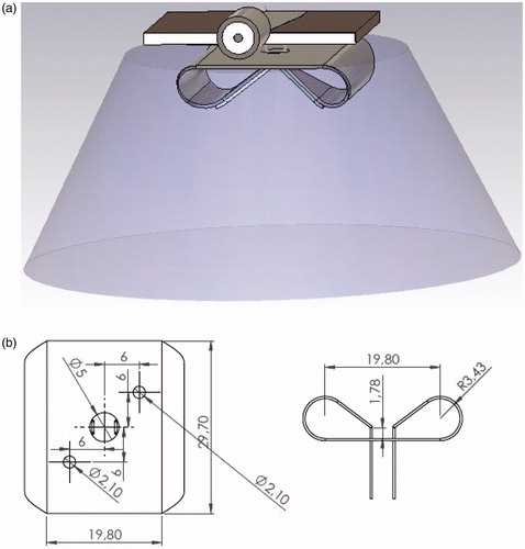
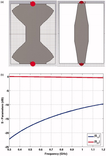
The basic design of the self-grounded Bow-Tie antenna in this paper follows the concepts described in [Citation19]. However, in order to reduce the size and provide a good impedance match to the patient, the antenna is immersed in demineralised water as shown in . The high permittivity of water reduces dimensions of the antenna to 24 × 27 × 11 mm3 and decreases the antenna impedance to 30 Ω. shows the physical dimension of the built Bow-Tie in top and side views. A rather unconventional RF-matching network which transfers 50–30 Ω is implemented and connected to the antenna with parallel rectangular pins. This is important to achieve the UWB characteristics of the antenna. In order to prevent the corrosion of the soldered metal tips in demineralised water, the pins are made from the same metal plate and bended through the hole in the ground plate. Thus the pins have the same thickness as the antenna plate, i.e. 0.45 mm. Self-heating of the pins at high powers is reduced by enlarging their cross section.
Figure 1. (a) The model of the self-grounded Bow-Tie antenna. (b) Schematic drawing of the manufactured antenna with its dimensions indicated, top and side views.
A further novelty in the design is the addition of a dielectric layer with low permittivity and low loss on top of the radiating arms of the Bow-Tie antenna. This will considerably improve the wide band performance as well as efficiency of the antenna. The length of dielectric layer defines the effective length of the dipole and hence defines its resonance frequency.
The propagated electric field along the arms of the antenna is faster in the part of the dielectric layer. As the wave is slowed down at the end of the dielectric layer, the electric field radiated by the antenna is intensified. This results in a well-defined dipole which in turn results in higher power density and the associated higher SAR values. The radiation pattern and the associated wave penetration have then again been considerably improved by further optimising the detailed shaping of the water bolus.
Balun
The purpose of balun is to guarantee good impedance matching of the antenna over its operational frequency band and minimise the power reflection losses. Specifically, the objective was to design a balun with reflection coefficient value less than −10 dB at a single-ended port in the frequency band of 0.4 to 1 GHz. The physical length of the balun was limited to 20 mm.
The real part of the impedance of the antenna was determined by numerical simulations, in which impedance values in range 15–50 Ω were applied on the feed lines of the antenna. A lower input impedance was necessary since an input impedance of 50 Ω, the antenna exhibits multiband behaviour with two resonance frequencies at 460 and 650 MHz. Moreover, with an input impedance of 50 Ω, the upper frequency is restricted to 750 MHz (S11< −10 dB). The bandwidth of the antenna is extended to 1 GHz when the impedance values are in the range 20–30 Ω. Additionally, these impedances yield relatively flat response in terms of reflection coefficient; namely the reflection coefficient is better than −10 dB in whole frequency band of interest. Therefore, the impedance of 30 Ω was considered as the most appropriate and the balun transforming the 30-Ω-impedance feed-line of the Bow-Tie antenna, ZL, to a 50-Ω-impedance of microstrip line (Z0) was designed.
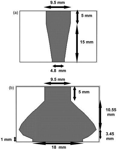
The balun consists of two parts: a parallel strip line and a microstrip transmission line. The geometry of the transition between microstrip and parallel strip balun is obtained by using the principles of exponential taper design [Citation21]. In the microstrip section of the balun, the width of the ground plane is changing gradually to the width of the parallel strip, . The width of the microstrip was calculated using the characteristic impedance equation in [Citation22], while the width of the ground plane was obtained by a parameter sweep. The design was realised on the Rogers 5880 laminate of thickness 1.5748 mm and ɛr = 2.2, which enable applications at high power.
Figure 2. Tapered balun geometry (a) front side and (b) back side.
Water bolus
In hyperthermia, a temperature-controlled circulating water bolus is used to couple electromagnetic energy into the patient and to control the skin surface temperature. Furthermore, it can be used as the immersion medium in order to decrease the size of the antenna [Citation10,Citation13]. In this work, we investigated if an antenna radiation pattern can be further improved by shaping the water bolus. The hypothesis was that water bolus of limited size provides more directed energy distribution inside the phantom and limits the coupling between the neighbouring antennas in the array [Citation23]. Hence, we split the water bolus into two segments: the surface water bolus (SWB) providing temperature control of the skin and the antenna water bolus (AWB) to enhance the performance of the antenna. The AWB and SWB have a separate cooling system to assure the stable behaviour of the antenna as well as full control of skin temperature.
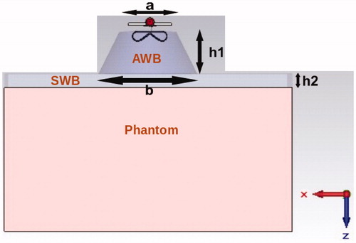
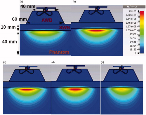
Potential benefits of AWB shaping are evaluated in terms of reflection coefficients and SAR distributions in the muscle phantom. Cylindrical and conical AWB are compared with standard large water bolus, common for all antennas in the array. We refer it as the rectangular shape. The dimensions of the best performing AWB were parameterised in terms of the dimensions of a truncated cone (a,b,h1) as shown in . To assess the effect of the surface water layer (h2), the two heights of 10 mm and 20 mm were considered.
Figure 3. Visualisation of the muscle load configuration.
Finally, the sensitivity of the reflection coefficients to variations in the water bolus temperature is evaluated. The water temperature in range 15 °C and 35 °C is modelled by using relaxation parameters of water extracted from the second order Debye model in [Citation24].
EM modelling and evaluation
Simulated results are obtained by using transient solver in CST Microwave Studio 2014 (CST, Darmstadt, Germany) [Citation25], which is based on FDTD. The antenna is evaluated in a muscle tissue load configuration as depicted in . A single antenna element is immersed in AWB with dimensions a, b, h1 and attached to a surface water bolus with thickness of 10 mm and a slab of homogeneous muscle tissue phantom with thickness 150 mm. The muscle phantom and surface water bolus have a rectangular shape of size 200 × 200 mm2. Dielectric properties of muscle and water are calculated using Cole–Cole dispersion relation model [Citation26]. The smallest mesh size of 0.5 mm resulted in a total amount of 2.4 million mesh cells. Perfectly matched layers (PML), which operate like free space and with minimum wave reflections, are used as boundary conditions.
The performance of the antenna was evaluated in terms of its reflection coefficient (S11), the effective field size (EFS) [Citation27] and penetration coefficient (pfTS) [Citation28]. The EFS is defined by the 50% SAR contour measured at a depth of 10 mm from the surface of the phantom.
In order to quantitatively evaluate the UWB characteristics of the antenna in the parametrization study, we defined
(1)
where |S11|avg is the average amplitude of reflection coefficient over the band, n is the number of frequency points in the frequency range of 0.4–1 GHz, where −20 dB <S11< −8 dB. Here Δ f is the frequency step used in the calculations. This parameter, a positive number, simply defines a range of frequencies in the desired frequency band for which the reflection coefficient is sufficiently small. The average value of |S11| over the entire band can be considered as a quality factor. The RCBW reflects the UWB behaviour of the antenna in a simple and comparable manner.
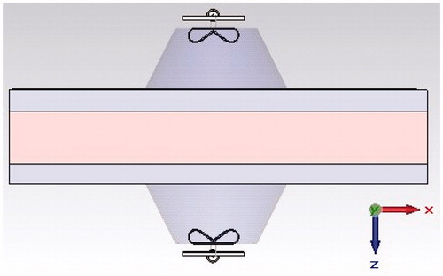
Transmission capability of the antenna was investigated using the setup shown in . Two identical antennas, of which one acts as transmitter and the other as receiver, were placed on two sides of the phantom with dimensions 200 × 200 × 25 mm3. Surface water layers of thickness 10 mm were placed on both sides between the phantom and antenna. The penetration coefficient pTS is defined as the ratio of the received power, Prec by the receiving antenna to the radiated power, Ptrans from the transmitting antenna
(2)
Figure 4. Setup for evaluation of penetration coefficient, pfTS.
In frequency domain, pTS was computed according to
(3)
where fl and fh are the lowest and highest frequencies in the operating frequency range of the antenna, respectively.
Results
Validation of the balun performance
The performance of the balun was evaluated in terms of the simulated reflection and transmission coefficients of the back to-back balun configuration. shows that the reflection coefficient varies from −20 dB at 0.4 GHz to −10.5 dB at 1 GHz. The lowest value of transmission coefficient is −0.3 dB at 1 GHz.
Figure 5. (a) Back-to-back balun and (b) simulated reflection and transmission coefficients of the balun in back-to-back configuration.
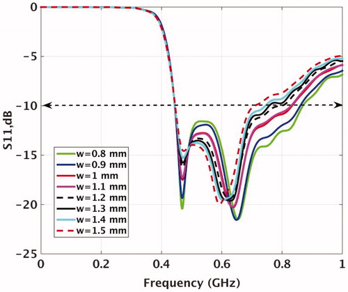
In order to reduce the self-heating of the connecting pins between the matching circuit and the antenna, we enlarged their surface area. The pins were considered as rectangular with the same thickness as antenna plate, i.e. 0.45 mm, to facilitate the manufacturing process of the antenna. shows variation of the reflection coefficients for pin width ranging from 0.8 mm to 1.5 mm. Clearly, the bandwidth of the antenna decreases with increased width. The pin width of 1.3 mm was found acceptable, with the reflection coefficients approximately −9 dB over the frequency range of 440–825 MHz, and it was used in the rest of the study.
Figure 6. Variation of the reflection coefficient of the antenna for various pin widths (simulated).
Dielectric layers
The effect of dielectric layers placed on top of the antenna arms is demonstrated in . From the amplitude of the surface current density presented in , it is apparent that the presence of dielectrics induces considerably higher currents distributed uniformly throughout the antenna arms and the ground plane. As a consequence, the electric field radiated by the antenna has been intensified, which results in higher propagation energy in the maximum radiation direction and increases the penetration of EM wave. Using a normal dielectric material with relative permittivity between 2–3 and low tangential losses is appropriate as shown in . Using a material with higher permittivity would require an increased length of the dielectrics, which is somewhat limited by the length of the Bow-Tie wings.
Figure 7. The effect of dielectric layers with 7.7 mm length on surface current density of the antenna at 500 MHz. (a) No dielectric and (b) dielectrics.
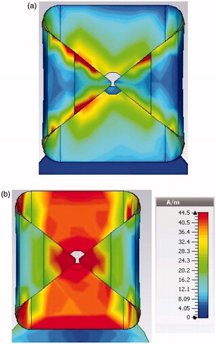
Figure 8. The effect of permittivity of dielectric layer on reflection coefficients of the antenna.
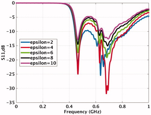
Figure 9. The effect of dielectric layers on E-field of the antenna at frequency 430 and 700 MHz along the cross section of the antenna at y = 0. E-fields are in V/m.
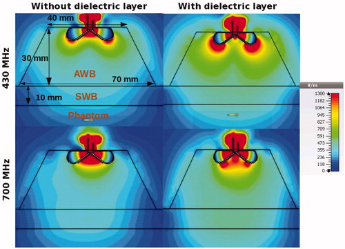
The penetration depth can be further improved by shaping the AWB. demonstrates the combined effect of the presence of dielectrics and conical shape of AWB at frequencies 430 and 700 MHz. Due to strong permittivity boundary of the conical walls, the wave is redirected towards the muscle phantom and thus contributes to increased intensity of the beam as well as increased penetration depth. Here, the input power was 10 W and the size of AWB was a/2= 20 mm, b/2= 35 mm, h1= 30 mm and h2= 10 mm.
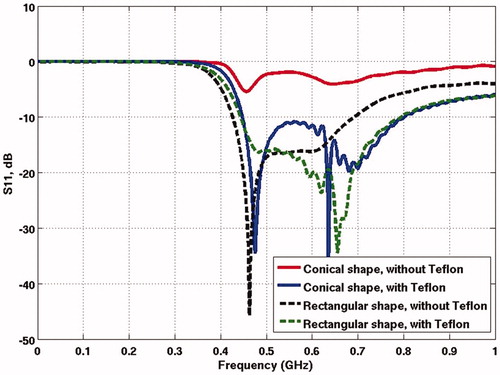
The dielectric layer has an important role in the design. A restricted AWB without this layer leads to high reflections, as exemplified in . As can be seen the reflection coefficient of the antenna with the dielectric layer is around 10 dB lower over the whole frequency band as compared with the one without dielectric layer.
Figure 10. Impact of dielectric layers on reflection coefficient of antenna immersed in large and limited AWB. The red and blue curves show the S11 without and with Teflon in conical shape AWB, respectively. The black and green curves show the S11 without and with Teflon in rectangular shape AWB, respectively.
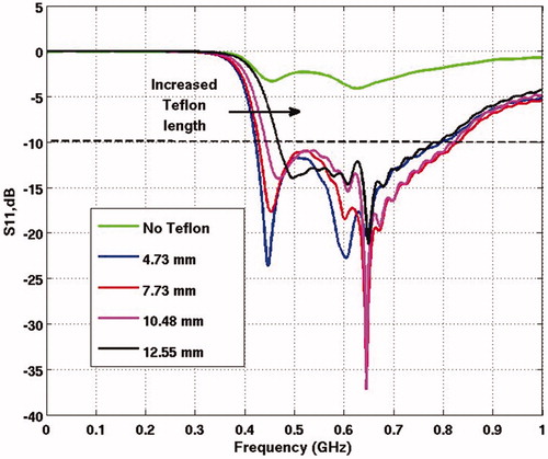
The sensitivity of the reflection coefficient to the length of dielectric layer is analysed in . Clearly, the lowest frequency shifts to higher values with an increased length. Since this frequency shift is not desired, the length of 7.7 mm which displays the minimum lower-bound frequency along with widest bandwidth was used in rest of the study.
Figure 11. Impact of length of dielectric layer on reflection coefficient of the antenna.
Parametrisation of the water bolus dimensions
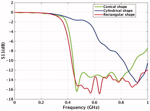
The impact of different AWB shapes on the reflection coefficients and the power density distributions in muscle phantom is shown in and . Three different AWB shapes were considered in this study; a rectangle with dimensions 100 mm × 100 mm, a cylinder with diameter 40 mm and a cone with upper and lower diameters 40 mm and 60 mm, respectively. The height of AWB was 20 mm in all cases studied.
Figure 12. The power loss density distribution in the muscle phantom for different AWB shapes. (a) Rectangular AWB without dielectric layer on the antenna arms. (b) Rectangular AWB with dielectric layer. (c) Cylindrical AWB. (d) Conical AWB.
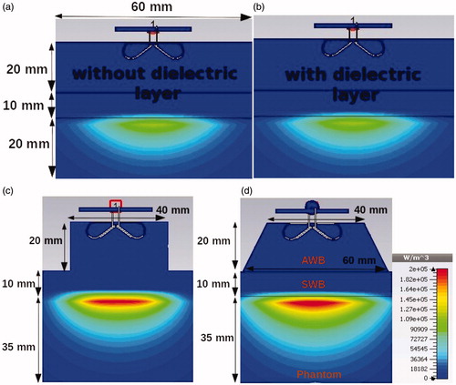
Figure 13. The reflection coefficient of the antenna with three different shapes of AWB.
At 500 MHz, the maximal power density in the phantom, 188 kW/ m3, is obtained for cylindrical AWB, . The power density values for conical AWB are comparable and approximately 50% higher than the rectangular shape. It is interesting to see from that the effect of dielectric layers on the antenna arms does not increase SAR values in the large bolus.
A relatively small cylindrical AWB upshifts the operation frequency band approximately 200 MHz as shown in . The reflection coefficients for rectangular and conical shapes are comparable although the S11 degrades faster at higher frequencies for the conical case.
Dimensions of the water bolus which give the most appropriate performance of the antenna, were determined with help of EFS, RCBW pfTS. and display dependence of EFS and RCBW on the base radius of the cone b/2 for various heights of the water bolus h1 and h2. The radius of top circle a/2 is given by the antenna size and kept fixed at 20 mm, . The maximal EFS, 48 mm2, is obtained for b/2 = 30 mm and heights h1 = 20 mm and h2 = 10 mm and decreases for larger bases, b. A comparable EFS can be achieved with h1 = 30 mm, if the base radius b/2 is increased 5 mm. A surface water layer with thickness h2 = 10 mm results in an EFS which is about 10 mm2 higher than for the h2 = 20 mm case.
Figure 14. Dependence of the EFS on dimensions of the water bolus.
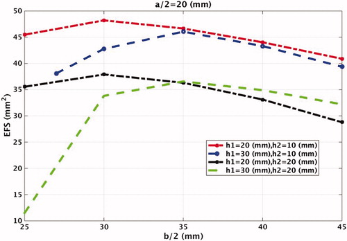
Figure 15. Dependence of the RCBW on dimensions of the water bolus.
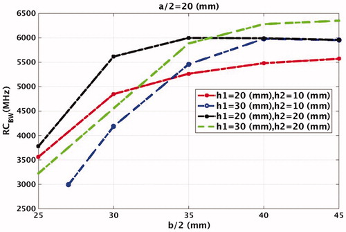
shows an increased RCBW for larger bases of the cone. The maximal value 6350 is thus obtained for the largest water bolus, i.e. for b/2 = 45 mm; h1 = 30 mm; h2 =20 mm. However, comparable values can be achieved with AWB height h1 = 20 mm and b/2 greater than 30 mm. Here, the frequency step, Δ f, is 1 MHz.
Another indicator of the antenna performance, the penetration coefficient pfTS is presented in . The cones with base radius larger than 40 mm were excluded due to poor EFS and large dimensions. The highest penetration coefficient pfTS=-3.86 dB is obtained for dimensions b/2 = 30 mm, h1 = 30 mm and h2 = 10 mm.
Table 1. pfTS in terms of AWB dimensions.
Experimental evaluation
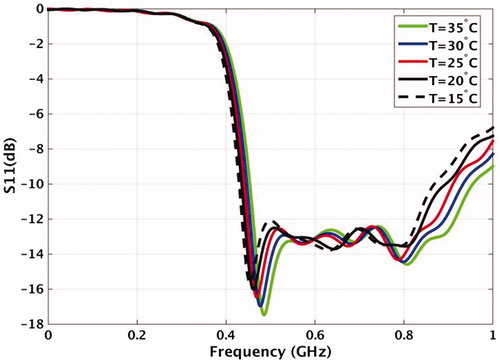
The antenna was manufactured and placed inside the AWB shaped with the shape of truncated cone with parameters a/2 = 20 mm, b/2 = 30 mm, h1 = 25 mm. In order to assure invariant reflection coefficient and to avoid overheating of the whole structure at high powers, the distilled water around the antenna should be kept at constant temperature. Sensitivity of the reflection coefficient of the antenna with water bolus temperature is illustrated in . The frequency band of the antenna (S11 < - 10, dB), with AWB dimensions a/2 = 20 mm; b/2 = 35 mm; h1 = 30 mm and h2 =10 mm is 0.43 GHz to 0.87 GHz for temperature 15 °C and 0.45 GHz to 0.95 GHz for temperature 35 °C. This corresponds to frequency shift of 1 MHz/°C.
Figure 16. Sensitivity of the reflection coefficient to temperature variations in water bolus.
demonstrates the stable radiation pattern over the whole frequency band of 430–1000 MHz, one of the most important parameters of the designed antenna.
Figure 17. Simulated power loss density distribution in muscle phantom for various frequencies. (a) 430 MHz, (b) 500 MHz, (c) 600 MHz, (d) 700 MHz and (e) 900 MHz.
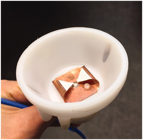
visualises the antenna prototype housed in a moulded plastic enclosure with the shape of a truncated cone. The top of the enclosure is covered by latex foil which provides firm but gentle attachment to the body and the inner space of the enclosure is filled with distilled water. The circulation of the water around the antenna is ensured by a refrigerated circulator connected to the antenna through two plastic tubes connected to the bottom of the housing.
Figure 18. The prototype of the manufactured antenna, including the UWB balun and the plastic enclosure.
Verification of antenna performance
The experimentally obtained heating ability of the antenna was verified by comparison of the temperature distribution in a muscle-equivalent phantom with the simulated SAR pattern. The arrangement of the experiment was similar to that shown in . A homogeneous muscle phantom (ɛr=60.4, σ =0.6 S/m) with dimensions 280 mm ×140 mm× 100 mm was pre-cut in the middle and two fibre optic probes with 14 sensors (FISO Technologies, Quebec, Canada) were placed in the depths of 6 and 12 mm, respectively. The surface water bolus in the form of a plastic bag with a thickness of 15 mm, filled with distilled water (ɛr=78, σ=0.05 S/m) was placed on the top of the phantom. The initial temperature of water in both water boil was the room temperature, i.e. 21 °C. The phantom was exposed to power of 10 W for 9 min. The thermal profile in the centre of phantom was measured by infra-red camera (B335, FLIR Systems, Wilsonville, OR) placed at distance 50 cm from the central plane of the phantom. The reflection coefficients were measured by a vector network analyser E8362B (Agilent Technologies, Santa Clara, CA).
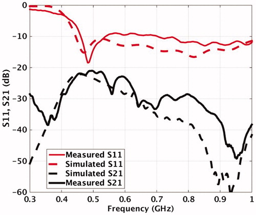
shows the measured and simulated reflection and transmission coefficients as a function of frequency. The simulated reflection coefficient is −10 dB or better in the frequency range 0.43–1 GHz. The measured reflection coefficient is comparable with the theoretical prediction, providing −9 dB or better in the frequency range 0.46–1 GHz. The mutual coupling between two antennas placed besides each other is better than −21 dB over the whole frequency range.
Figure 19. Measured and simulated reflection and transmission coefficients of the antenna.
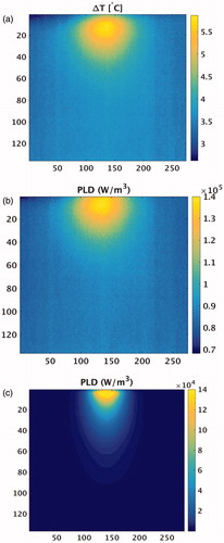
shows the temperature rise distribution in the central plane of the phantom obtained by an IR camera. The maximum temperature increase as measured with the fibre optic sensor was 6.5 °C. The SAR distribution was calculated from the measured temperature distribution, corresponds well with the SAR distribution predicted by the simulations, .
Figure 20. (a) The temperature rise distribution in a muscle phantom after exposure of 10 W for 9 min. (b) The SAR distribution in muscle phantom calculated from the measured temperature distribution. (c) The simulated SAR distribution in the muscle phantom. Frequency was 500 MHz in all cases.
MR compatibility
The compatibility of the antenna with a MR scanner was investigated inside a 1.5 Tesla MR scanner (Magnetom Symphony 1.5 T MRI, Siemens, Munich, Germany). The antenna was placed inside a rectangular plastic tank with dimensions 200 × 200 × 150 mm3, filled with water bags. The experiment was performed in two series. The first was performed with the antenna unattached to power source and the second with an unmounted SMA connector. The setup of the experiment is illustrated in , which shows the magnitude MR images captured with proton density + T2-weighted signals in the middle-coronal and axial planes. The axial cut was taken at a plane beneath the ground plane of the antenna. The black contours in both images represent the low permittivity structures such as air and dielectrics. Therefore, the antenna enclosure with some details such as water cooling tube is well visible.
Figure 21. The magnitude of MR images (a) proton density + T2-weighted images in middle-coronal and axial plane, without connector. (b) The echo time images in the axial plane, with connector. (c) The echo time images in the axial plane, without connector.
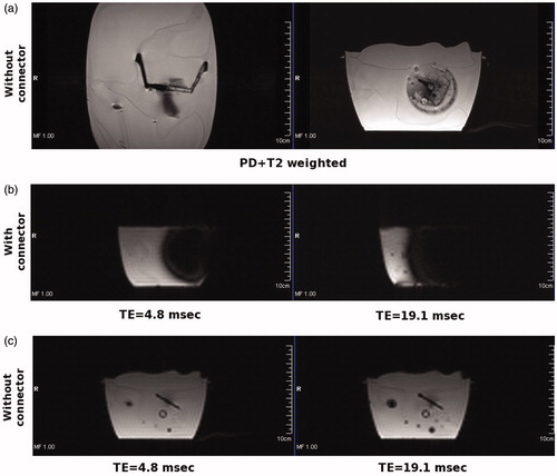
show the magnitude of MR images in the axial plane acquired with short (TE =4.8 ms) and long (TE =19.1 ms) echo times, typically used for MR-thermometry. The presence of the SMA connector causes a large distortion of the image. This distortion is caused by the magnetic susceptibility of the beryllium copper used in the connector. When the connector is unmounted, a nearly homogeneous image of the phantom is obtained. The inhomogeneites, represented by dark dots in images, are caused by air bubbles inside the water bags.
Discussion
In this paper, we presented new concepts in original self-grounded Bow-Tie design to enhance the radiation characteristics of the antenna and ensure an UWB operation in near-body applications. The antenna was miniaturised and immersed in distilled water to operate in the frequency range of 0.43–1 GHz. For matching purpose, a balun which transforms the impedance from 50 to 30 Ω was developed. Originally, the balun was connected with the antenna through the cylindrical pins with a radius of 0.25 mm soldered on both antenna and balun side. Experimentally we found that a power of 50 W caused temperature increase on the pins to 100 °C in only 15 min. To prevent this heating and ensure a power handling capability above 150 W, we increased the area of the pin to 1.3 × 0.5 mm2. In the final design, the pins are made from the same metal plate and bended through the hole in the ground plate in order to prevent the corrosion of the soldered metal tips in demineralised water. It should be mentioned that although the parametrisation study, i.e. , was performed with the original circular pins, the results are insensitive to the pin type.
The addition of dielectric layers on top of the radiating arms of the Bow-Tie results in considerably higher currents, distributed uniformly throughout the antenna arms and the ground plane. As a consequence, the electric field radiated by the antenna is increased, resulting in higher power density and the associated higher SAR values as demonstrated in and . This is achieved only for water bolus with reduced dimensions, such as the conical shape. Restriction of the water bolus dimensions often leads to worsening the antenna impedance matching, as shown in . However, the presence of dielectrics on the top of antenna arms compensates for this and provides comparable reflection coefficient as the water bolus of unlimited size.
We found the conical shape to be the most appropriate for our purpose, as it effectively propagates energy through the body and provides good impedance matching. A base with small radius causes a reflection of waves with longer wavelengths on the water–air boundary and thus hinders the operation at low frequencies. The wider opening of the cone prevents these reflections and re-directs the energy into the phantom. In combination with dielectric layer presented at the radiating arms, the absorbed energy in the phantom nearly doubles in comparison with water bolus of unlimited size.
In order to quantitatively evaluate the most appropriate dimensions of AWB, we used three performance indicators. We used the EFS, as defined in hyperthermia guidelines, to evaluate the ability of an antenna applicator to adequately heat superficial tumours. The ability to effectively transmit energy through the human body was assessed by the penetration coefficient (pfTS) while the maximum operational bandwidth was evaluated by RCBW. Definition of the RCBW parameter attempts to quantitatively evaluate the UWB characteristics in the parametrisation study. This parameter simply defines a frequency band for which the reflection coefficient is in the defined range. Since the antenna is considered to be an appropriate radiator when reflection coefficient is −10 dB or better, this number sounds decent. However, in our specific case, we used somewhat lower limit of −8 dB for a simple reason. As exemplified in and , the antenna often exhibits a peak in reflection coefficient around frequency 500 MHz. Suppression of this peak is too hard and might result in loosing bandwidth in the higher frequency range.
It can be seen from and that the EFS improves with smaller dimensions of AWB, while the RCBW deteriorates (lower values) with smaller dimensions of AWB. This quantitatively confirms the findings exemplified in and . From these results, we found the optimal cone dimensions to be a/2 = 20 mm, b/2 = 35 mm, h1= 30 mm, h2 = 10 mm. Due to space restriction of the final array applicator, we decided to manufacture a slightly smaller AWB with dimensions b/2 = 30 mm and h1 = 25 mm, which enables using higher antenna number in the final applicator design.
The antenna performance was evaluated on a muscle phantom of rectangular shape and with a water bolus layer placed on top [Citation29]. In the final applicator, the antenna elements will be arranged in circular or elliptical arrays placed around the patient body. Analogously to [Citation30], it can be expected a decrease of the EFS with increasing curvature in the direction perpendicular to the incident field (i.e. along the curvature).
The temperature of distilled water in the AWB should be kept constant since the reflection coefficient of the antenna shifts about 1.15 MHz/°C. Since the operation at low frequencies is more challenging, the water temperature should be kept rather low, ideally around 15 °C. At lower temperatures, the conductivity of the water increases which would increase unwanted dielectric losses. The circulation in the final design is assured by a refrigerated circulator connected to the antenna through two plastic tubes connected to the bottom of the housing.
The small deterioration of the measured reflection coefficient was caused by small air bubbles located on the top of the enclosure during the experiment, i.e. on the antenna ground plane. The presence of air was inevitable in the present arrangement without a degas filter. The small difference between measured and simulated SAR distribution in muscle phantom is caused by thermal conduction due to the relatively long heating time of 9 min. In order to accurately restore the SAR distribution from the temperature distribution, a short heating time of around 1 min is required. However, due to relatively low output power of the present power amplifier, a longer heating time was applied to handle the relatively low resolution of IR camera. The relatively low-output power of 10 W was also resulted in moderate temperature increase of 0.72 °C per minute. The MR image acquisition with antenna located inside MR bore indicated a negligible distortion of images by the antenna itself, which thus showed MR compatibility.
Conclusions
In this paper, we presented novel concepts in the design of self-grounded Bow-Tie antennas to serve as the basis antenna element in hyperthermia phased-array applicators. The UWB operation in the frequency range of 0.43–1 GHz is achieved by immersion of the miniaturised antenna in a water bolus. The water bolus was split in two layers: a surface water layer provides temperature control of the skin and compensates for geometrical irregularities while the AWB enhances the performance of the antenna. An appropriate shaping of the AWB along with inclusion of dielectric layers on the top of the radiating arms of the antenna significantly improves the energy delivery in the treated area. In order to find the most appropriate design, we further proposed a combination of three performance indicators. We believe that this combination can serve as a design criterion of antennas for near-field applications.
The antenna with a dielectric layer of length 7.7 mm, immersed in water bolus with shape of truncated cone with top radius of 20 mm, base radius of 35 mm and height 30 mm, yields the best compromise between EFS and RCBW. The thickness of surface water layer should be between 10–20 mm. An optimal was presented for the frequency band 430–1000 MHz and for water bolus temperature around 15 °C. Note that different dimensions of AWB would be optimal for the antenna aimed in sensing applications.
The antenna was constructed and experimentally validated on muscle-like phantom. The measured reflection coefficients as well as radiation characteristics are in excellent agreement with the simulated results. The antenna is compatible with MR scanners if non-magnetic, MR-compatible SMA connector replaces the present module.
In summary, the self-grounded Bow-Tie antenna enclosed in a water bolus with shape of truncated cone provides attractive design for use in hyperthermia phased array applications. It has a small size, operates in UWB frequency band with low mutual coupling and provides effective delivery of EM energy into the body.
Disclosure statement
The authors report no conflicts of interest. The authors alone are responsible for the content and writing of the article.
References
- Van der Zee J, Gonzalez DG, Van Rhoon GC, et al. (2000). Comparison of radiotherapy alone with radiotherapy plus hyperthermia in locally advanced pelvic tumours: a prospective, randomized, multicentre trial. Dutch Deep Hyperthermia Group Lancet 1:1119–25.
- Issels RD, Lindner LH, Verweij J, et al. (2010). Neo-adjuvant chemotherapy alone or with regional hyperthermia for localized high-risk soft-tissue sarcoma: a randomized phase 3 multicentre study. Lancet Oncol 11:561–79.
- Cihoric N, Tsikkinis A, van Rhoon G, et al. (2015). Hyperthermia-related clinical trials on cancer treatment within the Clinical Trials. gov registry. Int J Hyperth 31:609–14.
- Turner PF. (1984). Regional hyperthermia with an annular phased array. IEEE Trans Biomed Eng BME-31:106–14.
- Kroeze H, Van de Kamer JB, De Leeuw AAC, Lagendijk JJW. (2001). Regional hyperthermia applicator design using FDTD modelling. Phys Med Biol 46:1919–35.
- Crezee J, van Haaren PM, Westendorp H, et al. (2009). Improving locoregional hyperthermia delivery using the 3-D controlled AMC-8 phased array hyperthermia system: a preclinical study. Int J Hyperth 25:581–92.
- Paulides MM, Bakker JF, Neufeld E, et al. (2007). Winner of the "New Investigator Award" at the European Society of Hyperthermia Oncology Meeting 2007. The HYPERcollar: a novel applicator for hyperthermia in the head and neck. Int J Hyperthermia 23:567–76.
- Togni P, Rijnen Z, Numan WC, et al. (2013). Electromagnetic redesign of the HYPERcollar applicator: toward improved deep local head-and-neck hyperthermia. Phys Med Biol 58:5997–6009.
- Paulides MM, Vossen SHJA, Zwamborn APM, Van Rhoon GC. (2005). Theoretical investigation into the feasibility to deposit RF energy centrally in the head-and-neck region,. Int J Radiat Oncol Biol Phys 63:634–42.
- Dobšíček Trefná H, Vrba J, Persson M. (2010). Evaluation of a patch antenna applicator for time reversal. Int J Hyperthermia 185–97.
- Dobšíček Trefná H, Vrba J, Persson M. (2010). Time-reversal focusing in microwave hyperthermia for deep seated tumors. Phys Med Biol 2167–85.
- Gellermann J, Wlodarczyk W, Feussner A, et al. (2005). Methods and potentials of magnetic resonance imaging for monitoring radio frequency hyperthermia in a hybrid system. Int J Hyperthermia 21:497–513.
- Paulides MM, Bakker JF, Chavannes N, Van Rhoon GC. (2007). A patch antenna design for application in a phased-array head and neck hyperthermia applicator. IEEE Trans Biomed Eng 54:2057–63.
- Stauffer PR. (2005). Evolving technology for thermal therapy of cancer. Int J Hyperthermia 21:731–44.
- WustFähling P, Wlodarczyk H, Seebass W, et al. (2001). Antenna arrays in the SIGMA-eye applicator: interactions and transforming networks. Med Phys 28:1793–805.
- Persson M, Fhager A, Dobšíček Trefná H, et al. (2014). Microwave-based stroke diagnosis making global prehospital thrombolytic treatment possible. IEEE Trans Biomed Eng 61:2806–17
- Dobšíček Trefná H, Imtiaz A, Lui H, et al. (2012). Evolution of an UWB antenna for hyperthermia array applicator, 6th European Conference on Antennas and Propagation, 1046–1048.
- Bourqui J, Okoniewski M, Fear EC. (2010). Balanced antipodal Vivaldi antenna with dielectric director for near-field microwave imaging. IEEE Trans Antennas Propag 58:2318–26.
- Yang J, Kishk A. (2012). A novel low-profile compact directional ultrawideband antenna: the self-grounded bow-tie antenna. IEEE Trans Antennas Propaga 60:1214–20
- Abtahi S, Yang J, Kidborg S. (2012). A new compact multiband antenna for stroke diagnosis system over 0.5-3 GHZ. Microwave Opt Technol Lett 54:2342–6.
- Kobayashi M, Sawada N. (1992). Analysis and synthesis of tapered microstrip transmission lines. IEEE Trans Microwave Theory Techn 40:41–8.
- Bahl IJ, Trivedi DK. (1977). A designer’s guide to microstrip line. Microwaves 16:174–82.
- Dobšíček Trefná H, Takook J, Gellermann J, et al. (2010). Numerical evaluation of clinical applicator for hyperthermia treatment of Head and Neck tumors. 7th European Conference on Antennas and Propagation, 185–97.
- Buchner R, Barthel J, Stauber J. (1999). The dielectric relaxation of water between 0_ and 35. Chem Phys Lett 306:57–63.
- CST Microwave studio, CST GmbH. Bad Nauheimer Str. 19, 64289 Darmstadt, www.cst.com (last accessed 7 Nov 2016].
- Gabriel G, Lau RW, Gabriel C. (1996). The dielectric properties of biological tissues: III. Parametric models for the dielectric spectrum of tissues. Phys Med Biol 41:2271–93.
- Hand JW, Lagendijk JJW, Andersen JB, Bolomey JC. Quality assurance guidelines for Esho protocols. Int J Hyperthermia 5:421–8.
- Razavi A, Yang J. (2012). Investigation of penetration ability of UWB antennas in near-field sensing applications. 6th European conference on antennas and propagation, 791–5.
- Dobšíček Trefná H, Crezee J, Schmidt M, Marder D, et al. (2016). Quality assurance guidelines for the application of superficial hyperthermia clinical trials: II. Technical requirements for heating devices. Strahlentherapie und Onkologie, (Submitted for publication).
- Kok HP, Correia D, De Greef M, et al. (2010). SAR deposition by curved CFMA-434 applicators for superficial hyperthermia: measurements and simulations. Int J Hyperthermia 26:171–84.