
Abstract
Purpose: Radiofrequency (RF) energy is often used to create a linear lesion or discrete lesions for blocking the accessory conduction pathways for treating atrial fibrillation. By using finite element analysis, we study the ablation effect of amplitude control ablation mode (AcM) and bipolar ablation mode (BiM) in creating a linear lesion and discrete lesions in a 5-mm-thick atrial wall; particularly, the characteristic of lesion shape has been investigated in amplitude control ablation.
Materials and methods: Computer models of multipolar catheter were developed to study the lesion dimensions in atrial walls created through AcM, BiM and special electrodes activated ablation methods in AcM and BiM. To validate the theoretical results in this study, an in vitro experiment with porcine cardiac tissue was performed.
Results: At 40 V/20 V root mean squared (RMS) of the RF voltage for AcM, the continuous and transmural lesion was created by AcM-15s, AcM-5s and AcM-ad-20V ablation in 5-mm-thick atrial wall. At 20 V RMS for BiM, the continuous but not transmural lesion was created. AcM ablation yielded asymmetrical and discrete lesions shape, whereas the lesion shape turned to more symmetrical and continuous as the electrodes alternative activated period decreased from 15 s to 5 s. Two discrete lesions were created when using AcM, AcM-ad-40V, BiM-ad-20V and BiM-ad-40V. The experimental and computational thermal lesion shapes created in cardiac tissue were in agreement.
Conclusions: Amplitude control ablation technology and bipolar ablation technology are feasible methods to create continuous lesion or discrete for pulmonary veins isolation.
Introduction
Background
Atrial fibrillation (AF) is the most common cardiac arrhythmia in the general population. AF morbidity continuously increases with age. The common symptoms of AF include unpleasant and irregular heartbeats, impaired hemodynamic response caused by loss of atrioventricular synchrony, and vulnerability to thromboembolic complications [Citation1]. Thus, a successful AF treatment has three positive consequences: it restores the sinus rhythm, normalises cardiac hemodynamics and alleviates the vulnerability to thromboembolism. In the past, common therapies for AF were antiarrhythmic drugs or the surgical maze procedure. However, both these approaches may entail high recurrence and severe injury during the open chest surgery. Circumferential pulmonary vein isolation (PVI) and linear ablation in the left atrial (LA) roof have been demonstrated to be highly effective and reliable interventions against drug-resistant refractory AF [Citation2,Citation3]. Conventionally, PVI and LA ablation are performed through point-to-point ablation using unipolar RF energy guided by an electromagnetic navigation system (Carto™, Biosense Webster, or Ensite™, St. Jude Medical) for reducing radiation exposure. This RF ablation technique delivers a sinusoidal voltage from the active electrode to the dispersive electrode and creates a discrete lesion slightly larger than the size of the active electrode tip [Citation4]. In conventional unipolar ablation, continuous and linear lesions can be created by performing a series of discrete point ablation procedures, which requires a skilled operator; consequently, these procedures are often time intensive. Moreover, AF may recur because of incomplete linear lesion formation (i.e. presence of “gaps”), resulting in partially recovered accessory conduction pathways.
Recently, the multipolar RF ablation technology has recently been clinically investigated for treating AF. Spitzer et al. conducted several clinical studies in which they compared the success rate and effectiveness of point-to-point ablation and multipolar phase RF ablation in 539 patients [Citation5]. Basu et al reported that the bipolar ablation for AF was substantially shorter of procedure time and a greater guarantee of transmural lesions compared with the unipolar ablation [Citation6]. Rodriguez et al. used the novel circular irrigated multipolar ablation catheter to perform PVI; they reported that PVs isolation with multipolar catheter is a feasible technique with a high acute success rate [Citation7].
Therefore, developing multipolar RF ablation procedures that facilitate the easy creation of continuous lesions in PVs or LA and additional discrete lesions for eliminating “gaps” are essential for treat AF. In this paper, we use finite element analysis method to investigate the formation of continuous lesions and additional discrete lesions created by amplitude control ablation technology and bipolar ablation technology. A review of relevant literature revealed that no finite element model has yet been developed to study the amplitude control ablation technology in creating continuous lesions and discrete lesions; particularly, the characteristic of lesion shape has not been investigated in amplitude control ablation. In our paper, we studied the multi-channel amplitude control ablation and bipolar ablation. In clinical practice, the multi-channel RF generator (GENius, Medtronic, Minneapolis, MN) was applied to the clinical studies. This generator offers the multi-channel bipolar/unipolar energy output. From the instructions of this device, the RF voltage was delivered in a temperature-controlled and power-limited manner with a maximum of 8 W per electrode. Therefore, we choose the root mean squared value of the RF voltage 20/40 V approximately 5/10 watts of bipolar/unipolar power applying to amplitude control ablation mode and bipolar ablation mode.
Methods
Amplitude control ablation technology
The amplitude control ablation technique delivers a pair of RF voltage at different amplitude but the same frequency and phase angle to the adjacent active electrodes. The amplitude difference between the RF sources induces a voltage gradient in the adjacent active electrodes, leading to the flow of bipolar current in the myocardium. Meanwhile, the unipolar current also flows between active and dispersive electrodes, as illustrated in . In AcM ablation, active electrode “a” and “c” are set at V1 (t) = A1 sin ω t, and active electrode “b” and “d” are set at V2 (t) = A2 sin ω t; the dispersive electrode is grounded. illustrated the conventional bipolar ablation mode. In this ablation mode, active electrode “a” and “c” are set at V1 (t) = A1 sin ω t, and active electrode “b” and “d” are set at V2 (t) = 0; the dispersive electrode is not connected.
Figure 1. The principle of amplitude control ablation and bipolar ablation.
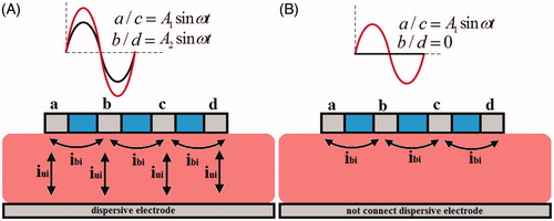
According to the basic circuit principle and trigonometric relationship, the amplitude of bipolar voltage and unipolar voltage in two kind of ablation modes is illustrated in .
Table 1. Induced bipolar and unipolar voltage in AcM and BiM.
Bio-heat equation
The physical phenomenon for the coupled thermal-electric problem is governed by the Penne’s bio-heat transfer equation [Citation8]:
(1)
where T (°C), ρ (kg/m3), c (J/kg·K), k (W/m·K) and q (W/m3) are the temperature, density, specific heat, thermal conductivity and power density, respectively, and Qb and Qm represent the blood perfusion and metabolic heat, respectively. The metabolic heat production per volume term Qm is ignored in our study because it is far smaller than the other terms [Citation9]. We also ignored the blood tissue and blood perfusion, as was the case in Schutt et al. [Citation9]. The power loss produced by the blood flow is modelled by means of forced thermal convection coefficients in the electrodes–blood interface and endocardium–blood interface.
At the RF frequencies (such as 500 kHz), the mechanism of RF current induces myocardium injury is Joule heating due to the conduction currents [Citation10]. The power density q produced by the electric field was obtained from the product of current density J = σ E and electric field intensity E = - ∇ V, where σ is the electrical myocardium conductivity and V represents the electric potential. The electric potential is obtained by solving EquationEquation (2)(2) , which is the governing equation of the electrical problem in absence of internal electric sources.
(2)
In this study, we used the quasi-static electrical equation to resolve the electro-thermal coupled problem. In this quasi-static approach, the direct-current voltage corresponding with the root mean squared value of the RF voltage is applied to the finite element model of the catheter electrode [Citation11,Citation12].
Construction of the computer model
We developed a two-dimensional ablation model and used it to represent the different ablation modes through applying special boundary conditions. depicts the model for cardiac ablation (not to scale). To model AcM and BiM, the multipolar catheter, which includes the four active electrodes and three plastic probe, was placed horizontally on the endocardium, as shown in . A fragment of the pericardial fluid and the atrial wall was considered in the model [Citation13,Citation14]. Because the atrial wall thickness ranges from 1.2 to 6.5 mm [Citation15], we constructed an atrial wall of thickness 5 mm.
Figure 2. The geometry of computational model (not to scale). The thickness of atrial wall is 5 mm. Details of the electrodes are: Electrode diameter D = 2.31 mm (7 Fr), electrode lengths L= 3 mm, insertion depth 0.5 mm and electrode spacing 4 mm.
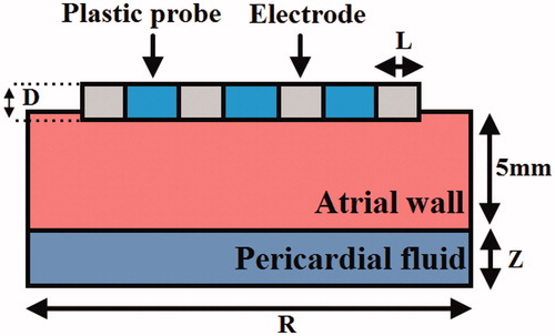
Model dimensions Z and R were calculated through a convergence analysis to avoid boundary effects, and also the adequate spatial and temporal resolution were estimated using similar convergence test. The maximal temperature (Tmax) in the tissue after 60 s or 120 s of ablation was used as the control parameter in the convergence tests. First, a tentative spatial and temporal resolution was considered to determine the appropriate Z and R. We then equally increased Z and R. When the difference in the Tmax between consecutive simulations was less than 0.5%, we considered the dimensions obtained in the preceding step to be adequate. The dimensions were determined separately for each ablation mode and applied voltage. Finally, by using convergence tests and the same control parameter, we determined the adequate spatial and temporal resolution.
In this paper, we used ANSYS 14.0 for building the finite element model and for conducting a solution and Tecplot 360 EX 2015 for post-processing.
Material characteristics
lists the characteristics of the materials considered in the numerical model [Citation13,Citation14]. The electrical and thermal conductivity of the myocardium was modelled using the temperature-dependent piecewise function [Citation16]. As the temperature increased to less than 100^ C, the electrical conductivity first increased exponentially (1.5% circC) and then decreased by a factor of 10 000 between 100;circ C and 105;circ C whereas the thermal conductivity increased linearly by 1.2% ^ C up to 100;circ C, following which it remained constant at temperatures exceeding 110 °C.
Table 2. Thermal and electrical characteristics of the elements of the numerical models.
Boundary condition
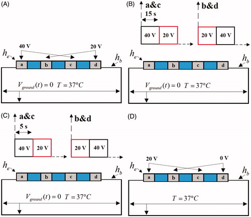
illustrates the electrical boundary conditions 1 of ablation modes. In these conditions, the active electrodes “a” & “c” were set at one voltage value while the active electrodes “b” & “d” were set at another voltage value. In AcM (), a constant zero voltage at the border (mimicking the electrical performance of the dispersive electrode) and two kind of voltages 40 V and 20 V were applied to active electrodes “a” & “c” and “b” & “d”, respectively in whole ablation time. In AcM-15s and in AcM-5s (), a constant zero voltage at the border and two kind of voltages 40 V and 20 V were alternately applied to the pair of the electrodes “a” & “c” and “b” & “d”, respectively with alternative period 15 s and 5 s. In BiM (), the active electrodes “a” and “c” were set at 20 V, and the other active electrodes “b” and “d” were set at zero voltage to ensure that the electrical currents were forced to flow between each active electrodes.
Figure 3. Electrical and thermal boundary conditions 1.
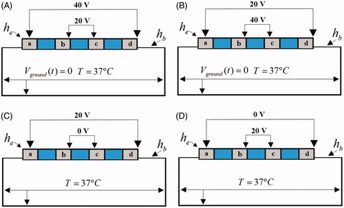
illustrates the electrical boundary conditions 2 of ablation modes. In these conditions, the outer side electrodes “a” & “d” were set at the one voltage value while the inner side electrodes “b” & “c” were set at another voltage value. In the AcM-ad-40V (), a constant zero voltage at the border and two kind of voltages 40 V and 20 V were applied to active electrodes “a” & “d” and “b” & “c”, respectively. In the AcM-ad-20V (), a constant zero voltage at the border and two kind of voltages 20 V and 40 V were applied to active electrodes “a” & “d” and “b” & “c”, respectively. In the BiM-ad-20V (), the 20 V was applied to the pair of electrode (“a” & “d”) and 0 V was applied to another pair of electrode (“b” & “c”). In the BiM-ad-0V mode (), the zero voltage was applied to the pair of electrode (“a” & “d”) and 20 V was applied to another pair of electrode (“b” & “c”).
Figure 4. Electrical and thermal boundary conditions 2.
The thermal boundary condition was a constant temperature of T = 37;^ C at the border of all models. The cooling effect produced by blood flow inside the atrium was modelled using two forced thermal convection coefficients—708 and 3636 W/m2 K—for the endocardium–blood (hb) and electrode–blood (he) interfaces, respectively [Citation9].
Experimental setup
In our simulation, we studied effect of special electrodes activated ablation methods on lesions shape in amplitude control ablation technology and bipolar ablation technology. To validate the theoretical results in this study, an in vitro experiment with porcine cardiac tissue was performed. A multichannel controllable amplitudes RF generator (450 kHz) was developed by our laboratory and a multipolar catheter with diameter D = 2.31 mm, electrode lengths L = 3 mm and spacing 4 mm was manufactured by Shanghai MicroPort EP MedTech Co., Ltd. This multipolar catheter has ten active electrodes. In our experiment study, we activated four of adjacent active electrodes and the other electrodes were not used. The porcine cardiac tissues were acquired from a local grocery store. The size of tissue specimens was kept at approximate 20–30 mm thickness. The catheter was placed horizontally on the endocardium. The cardiac tissue was put on aluminium foil acting as the ground pad in amplitude control ablation modes.
Assessment of the thermal injury
Although tissue injury is the result of several complex mechanisms, thermal lesions created in the atrial wall can be reasonably approximated using an isotherm of 50 °C in computer models [Citation17,Citation18] and thermal lesion contour in the experiments is assessed by the “white zone” [Citation19].
Results
Ablation modes with the electrical boundary conditions 1
presents the temperature distributions and the shapes of the lesion in the atrial wall for the four ablation modes corresponding to the boundary conditions 1 in . The thermal injury was approximated using the thermal damage borderline: the isotherm of 50 °C, which outlines the width and depth of the lesions. lists the maximum depth and width of the lesions created in the four ablation modes.
Figure 5. Temperature distribution in the atrial tissue after 60s or 120s of RF ablation across 5 mm wall thickness, considering four modes of ablation: (A) AcM, (B) AcM-15s, (C) AcM-5s and (D) BiM. The solid black line is the thermal damage border.
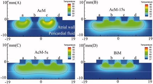
Table 3. Lesion dimensions for four modes of RF ablation: AcM, AcM-15s, AcM-5s and BiM.
In AcM mode with 60 s ablation time (), the discontinuous and transmural lesions were generated in the 5-mm-thick atrial wall. The significant finding was that the AcM ablation yielded the asymmetrical lesion area: the maximum lesion depth and width were 5.51 mm and 9.98 mm, respectively. The other important found was the AcM mode generated two discrete lesions with asymmetrical lesion size. However, In AcM-15s and AcM-5s modes with 60 s ablation time (), as the electrodes alternative activated period decreased from 15 s to 5 s, the lesions shape turned to more symmetrical and the continuous lesion was yielded. In BiM mode with 120 s ablation time (), the continuous but not transmural lesion was generated in the 5-mm-thick atrial wall. BiM ablation yielded the symmetrical lesion area: the maximum lesion depth and width were 3.87 mm and 20.14 mm, respectively. In amplitude control ablation technology with alternately activated electrodes method (AcM-15s and AcM-5s), it was found from the simulation results that the maximum lesion depth and width were greater than bipolar ablation mode (seeing ).
Ablation modes with the electrical boundary conditions 2
In our simulation, we studied effect of special electrodes activated ablation methods on lesions shape in amplitude control ablation technology and bipolar ablation. presents the temperature distributions and the shapes of the lesion in the atrial wall for the four ablation modes corresponding to the boundary conditions 2 in . lists the maximum depth and width of each single lesion in these four ablation strategies.
Figure 6. Temperature distribution in the atrial tissue after 60s or 120s of RF ablation across 5 mm wall thickness, considering four modes of ablation: (A) AcM-ad-40V, (B) AcM-ad-20V, (C) BiM-ad-20V and (D) BiM-ad-0V. The solid black line is the thermal damage border.
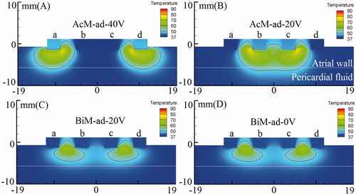
Table 4. Lesion dimensions for four modes of RF ablation: AcM-ad-40V, AcM-ad-20V, BiM-ad-20V and BiM-ad-0V.
In AcM-ad-40V mode with 60 s ablation time (), the high ablation voltage was applied to outer side electrodes “a” & “d”. We found that it yielded the outward expansion discrete lesions because the high ablation voltage applied to outer side electrodes. The maximum lesion depth and width for each single lesion were 5.39 mm and 9.75 mm, respectively. In AcM-ad-20V mode with 60 s ablation time (), the high ablation voltage was applied to inner side electrodes “b” & “c”. We observed that the lesion shape in AcM-ad-20V ablation differed significantly from those obtained through AcM-ad-40V, BiM-ad-20V and BiM-ad-0V. The continuous and transmural lesion was generated in the 5-mm-thick atrial wall with the maximum lesion depth and width were 5.80 mm and 17.32 mm, respectively in AcM-ad-20V mode. In BiM-ad-20V and BiM-ad-0V modes with 120 s ablation time (), the identical bipolar voltage difference (20 V) was induced between adjacent active electrodes (“a” to “b” and “c” to “d”), meanwhile there was not unipolar voltage induced in the two ablation modes. Therefore the similar lesion shape was yielded in BiM-ad-20V and BiM-ad-0V.
Experimental validation
In the experiment study, we do not mimic the cooling effect produced by the blood circulating inside the ventricles. Therefore, we performed the additional simulations in all ablation modes which do not considered the forced thermal convection coefficients on endocardium–blood and electrode–blood interfaces. show the experimental and computational thermal lesions which were assessed by the “white zone” in the experiments and the isotherm of 50 °C in the computer results. lists the maximum depth and width of the lesions in vitro experiments and computer simulations. In the experiment study, we investigated the lesion shape creating by all ablation modes. As can be seen, the experimental and computational thermal lesion shapes created in cardiac tissue were in agreement. However, these are also some discrepancies in maximum lesion depth and width between experiment and simulations that may come from three reasons: (1) not all the sliced tissue specimens were the same size; (2) in experiment the catheter was placed horizontally on the endocardium and was not exactly inserted depth with 0.5 mm; (3) underestimation of lesion size in the in vitro experiment using the white zone method.
Figure 7. Experimental and computational results for ablation modes.
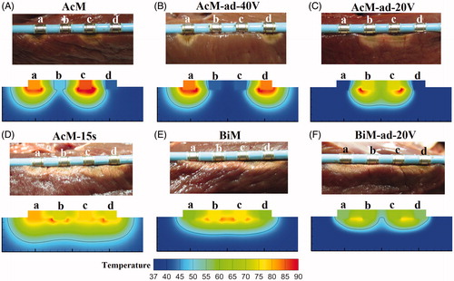
Table 5. Comparisons of maximum lesion depth and width from in vitro experiments and the computer results.
Discussion
The main objective of this paper was to study the lesion features and ablation effect of amplitude control ablation technology and bipolar ablation technology in creating a continuous lesion and discrete lesion for treating AF.
In the amplitude control ablation technology, we discover a phenomenon for the first time that the discrete and asymmetrical lesions shape was created when using AcM ablation, and the discrete but symmetrical lesions shape is yielded in AcM-ad-40V ablation. We also found that the continuous lesions were generated as we alternately activated the electrodes in AcM-15s and AcM-5s modes. In the AcM-ad-20V mode, the continuous lesion was also yielded but with shorter lesion width compared with AcM-15s and AcM-5s modes. These results suggest that we can control the length of continuous lesion for PVI and LA ablation through activating special electrodes, such as creating long or short continuous lesion (seeing ).
The simulation and in vitro experiment results demonstrate that the continuous lesion was also created in BiM mode because the bipolar voltage is induced between adjacent electrodes and it is know that the bipolar voltage contributes to the formation of continuous and deeper lesions. These findings are consistent with those of Gizurarson et al., who studied bipolar energy to create linear and deeper lesions in an in vivo experiment [Citation20]. In BiM ablation, it can yield a continuous and symmetrical lesion and it is suitable for creating a uniform lesion to complete circumferential the PVI. In the clinic research, Shin et al. assessed the safety and effectiveness of a novel irrigated multipolar catheter for PVI. In their study, unipolar energy was delivered simultaneously in the antral region of the PVs from the nMARQ catheter (Biosense Webster Inc., Diamond Bar, CA) to create ten discrete lesion points [Citation21]. This multichannel RF ablation technique is superior to and is faster than the single ablation technique for PVI, but the orientation of circular catheter must be changed for complete PVI. By contrast, circumferential lesions can be created easily around PVs with minimal or no catheter movement if BiM, AcM-ad-20V, AcM-15s or AcM-5s modes is applied to the multipolar catheter.
and Citation6(A,C,D) show the discrete lesion shape. In these ablation modes (AcM, AcM-ad-40V, BiM-ad-20V and BiM-ad-0V), two discrete lesions area are created. To thoroughly complete the circumferential PVI and LA linear ablation, additional discrete ablation points are needed to solve the incomplete linear lesion formation presence of “gaps” and inadequate ablation which will cause the relapse of AF [Citation22]. Due to the discrete distribution of thermal lesion features, we can use these ablation methods to perform the additional ablation to complete circumferential PVI and LA linear ablation and ensure the success of the treatment of AF.
Some theoretical studies have concluded that unipolar ablation can create discrete lesions and transmural lesions on 1–3 mm thick myocardium but at high ablation voltage and power, for example, at 42.5 V amplitude and 35 W [Citation13,Citation23]. Whereas the amplitude control ablation technology is able to create transmural lesions in 5-mm-thick atrial walls with low ablation voltage (40/20 V RMS). In persistent AF, circumferential pulmonary vein isolation and additional linear ablations at the left atrial roof are often needed to increase success rates; however, oesophageal fistula and PV stenosis may occur due to the undesirable extension of the thermal damage depth [Citation24,Citation25]. We discover that the maximal temperature point in atrial tissue is beneath the plastic catheter in some ablation modes (AcM-15s, AcM-5s, BiM, AcM-ad-20V, BiM-ad-20V and BiM-ad-0V), whereas, in unipolar ablation, the maximal temperature point is near to the active electrode [Citation26]. We know that the temperature sensor is usually attached to the bottom of the active electrode to sense real-time temperature, therefore the target temperature should be set lower in order to avoid the excessive thermal damage appeared between the active electrodes when using the AcM-15s, AcM-5s, BiM, AcM-ad-20V, BiM-ad-20V and BiM-ad-0V ablation.
Study limitations
This study has certain limitations. We used a nonirrigated catheter to perform cardiac ablation. To create complete transmural lesions or deeper lesions in the thick atria, irrigated catheter should be used [Citation27]. In this study, the RF voltage was fixed at constant value (20 V or 40 V RMS) for the entire ablation duration. However, in clinical application, the power delivery protocol is usually based on a constant temperature algorithm, where a voltage boundary condition on the active electrode is adjusted to maintain a constant electrode tip temperature [Citation28]. Furthermore, studying all the ablation modes at different energy modalities, such as damped pulses, nondamped pulses and constant current amplitude, are expected to yield useful results [Citation29–31]. To obtain comprehensive results, the bipolar voltage difference setting should be refined, rather than using 20 V RMS, as was the case in this study.
The blood flow was modelled using a fixed convection coefficient on the electrode–blood and endocardium–blood interface, which is only representative of a constant blood flow rate. But in clinic applications, the blood flow rate varies with the heart diastolic and systolic variables [Citation32]. An accurate method to model the blood flow was consider the blood as a laminar fluid flow with the high and low flow velocities instead of using convective boundary conditions [Citation33,Citation34]. Therefore, temperature distribution in tissue region varies slightly because of the varying blood flow rate in one cardiac cycle. Moreover, the blood tissue and blood perfusion are ignored in simulations. In simulation models, we have determined the ablation voltage amplitude and ablation time to restrict the maximum tissue temperature less than 100 °C during the entire procedure. Therefore, we have not considered the phase change in tissue vaporisation to simulate its dissection when it reaches a temperature higher than 100 °C.
Conclusions
The simulation and in vitro experiment results demonstrate that the continuous lesion can created in a single ablation procedure when using multipolar catheter by using AcM-15s, AcM-5s, BiM and AcM-ad-20V modes. Two discrete lesions shape can yield in AcM, AcM-ad-40V, BiM-ad-20V and BiM-ad-0V modes to complete additional ablation in inadequate ablation regions. Therefore, amplitude control ablation technology and bipolar ablation technology are suitable for complete circumferential PVI and LA linear ablation for treating AF.
Disclosure statement
This work received financial support from Science and Technology Commission of Shanghai Municipality, China, grant no. 16441907900, the Shanghai Engineering Research Center of Assistive Devices, China, grant no. 15DZ2251700 and the Shanghai Science and Technology Committee Support Program, China, grant no. 13DZ1941802. We would like to thank the Shanghai MicroPort EP MedTech Co., Ltd. for providing multipolar catheter. The authors alone are responsible for the content and writing of the paper.
Additional information
Funding
References
- Furberg CD, Psaty BM, Manolio TA, et al. Prevalence of atrial fibrillation in elderly subjects (the Cardiovascular Health Study). Am J Cardiol 1994;74:236–41.
- Wang Y, Liu X, Tan H, et al. Evaluation of linear lesions in the left and right atrium in ablation of longstanding atrial fibrillation. Pacing Clin Electrophysiol 2013;36:1202–10.
- O'Neill MD, Wright M, Knecht S, et al. Long-term follow-up of persistent atrial fibrillation ablation using termination as a procedural endpoint. Eur Heart J 2009;30:1105–12.
- Guerra JM, Jorge E, Raga S, et al. Effects of open-irrigated radiofrequency ablation catheter design on lesion formation and complications: in vitro comparison of 6 different devices. J Cardiovasc Electr 2013;24:1157–62.
- Spitzer S, Karolyi L, Weinmann T, et al. Multielectrode phased radiofrequency ablation compared with point by point ablation for pulmonary vein isolation outcomes in 539 patients. Res Rep Clin Cardiol 2014;5:11–20.
- Basu S, Nagendran M, Maruthappu M. How effective is bipolar radiofrequency ablation for atrial fibrillation during concomitant cardiac surgery? Interact Cardiovasc Thorac Surg 2012;15:741–8.
- Rodriguez Entem F, Exposito V, Rodriguez Manero M, et al. Initial experience and treatment of atrial fibrillation using a novel irrigated multielectrode catheter: results from a prospective two-center study. J Arrhythm 2016;32:95–101.
- Penns HH. Analysis of tissue and arterial blood temperatures in the resting human forearm. J Appl Physiol 1948;1:93–122.
- Schutt D, Berjano EJ, Haemmerich D. Effect of electrode thermal conductivity in cardiac radiofrequency catheter ablation: a computational modeling study. Int J Hyperthermia 2009;25:99–107.
- Doss JD. Calculation of electric fields in conductive media. Med Phys 1982;9:566.
- Mulier S, Jiang Y, Wang C, et al. Bipolar radiofrequency ablation with four electrodes: ex vivo liver experiments and finite element method analysis. Influence of inter-electrode distance on coagulation size and geometry. Int J Hyperthermia 2012;28:686–97.
- Berjano EJ. Theoretical modeling for radiofrequency ablation: state-of-the-art and challenges for the future. Biomed Eng Online 2006;5:24.
- Perez JJ, D'Avila A, Aryana A, Berjano E. Electrical and thermal effects of esophageal temperature probes on radiofrequency catheter ablation of atrial fibrillation: results from a computational modeling study. J Cardiovasc Electrophysiol 2015;26:556–64.
- Gonzalez-Suarez A, Trujillo M, Koruth J, et al. Radiofrequency cardiac ablation with catheters placed on opposing sides of the ventricular wall: computer modelling comparing bipolar and unipolar modes. Int J Hyperthermia 2014;30:372–84.
- Ho SY, Sanchez-Quintana D, Cabrera JA, Anderson RH. Anatomy of the left atrium: Implications for radiofrequency ablation of atrial fibrillation. J Cardiovasc Electrophysiol 1999;10:1525–33.
- Trujillo M, Berjano E. Review of the mathematical functions used to model the temperature dependence of electrical and thermal conductivities of biological tissue in radiofrequency ablation. Int J Hyperthermia 2013;29:590–7.
- Nath S, Lynch C, Whayne JG, Haines DE. Cellular electrophysiological effects of hyperthermia on isolated guinea pig papillary muscle. Implications for catheter ablation. Circulation 1993;88:1826–31.
- Yan S, Wu X, Wang W. A simulation study to compare the phase-shift angle radiofrequency ablation mode with bipolar and unipolar modes in creating linear lesions for atrial fibrillation ablation. Int J Hyperthermia 2016;32:231–8.
- González-Suárez A, Trujillo M, Burdío F, et al. Could the heat sink effect of blood flow inside large vessels protect the vessel wall from thermal damage during RF-assisted surgical resection? Med Phys 2014;41:83301.
- Gizurarson S, Spears D, Sivagangabalan G, et al. Bipolar ablation for deep intra-myocardial circuits: human ex vivo development and in vivo experience. Europace 2014;16:1684–8.
- Shin D, Kirmanoglou K, Eickholt C, et al. Initial results of using a novel irrigated multielectrode mapping and ablation catheter for pulmonary vein isolation. Heart Rhythm 2014;11:375–83.
- Kuck K, Hoffmann BA, Ernst S, et al. Impact of complete versus incomplete circumferential lines around the pulmonary veins during catheter ablation of paroxysmal atrial fibrillation. Circ Arrhythm Electrophysiol 2016;9:e3337.
- Berjano EJ, Hornero F. Thermal-electrical modeling for epicardial atrial radiofrequency ablation. Ieee Trans Biomed Eng 2004;51:1348–57.
- Ravenel JG, McAdams HP. Pulmonary venous infarction after radiofrequency ablation for atrial fibrillation. AJR Am J Roentgenol 2002;178:664–6.
- Martinek M, Bencsik G, Aichinger J, et al. Esophageal damage during radiofrequency ablation of atrial fibrillation: impact of energy settings, lesion sets, and esophageal visualization. J Cardiovasc Electr 2009;20:726–33.
- Suarez AG, Hornero F, Berjano EJ. Mathematical modeling of epicardial RF ablation of atrial tissue with overlying epicardial fat. Open Biomed Eng J 2010;4:47–55.
- Gopalakrishnan J. A mathematical model for irrigated epicardial radiofrequency ablation. Ann Biomed Eng 2002;30:884–93.
- Jain MK, Wolf PD. Temperature-controlled and constant-power radio-frequency ablation: what affects lesion growth? IEEE Trans Biomed Eng 1999;46:1405–12.
- Goldberg SN, Stein MC, Gazelle GS, et al. Percutaneous radiofrequency tissue ablation: optimization of pulsed radiofrequency technique to increase coagulation necrosis. J Vasc Interv Radiol 1999;10:907–16.
- Berjano EJ, Alio JL, Saiz J. Modeling for radio-frequency conductive keratoplasty: implications for the maximum temperature reached in the cornea. Physiol Meas 2005;26:157–72.
- Zhang B, Moser MA, Zhang EM, et al. Numerical analysis of the relationship between the area of target tissue necrosis and the size of target tissue in liver tumours with pulsed radiofrequency ablation. Int J Hyperthermia 2015;31:715–25.
- Tungjitkusolmun S, Vorperian VR, Bhavaraju N, et al. Guidelines for predicting lesion size at common endocardial locations during radio-frequency ablation. IEEE Trans Biomed Eng 2001;48:194–201.
- Gonzalez-Suarez A, Berjano E. Comparative analysis of different methods of modeling the thermal effect of circulating blood flow during RF cardiac ablation. IEEE Trans Biomed Eng 2016;63:250–9.
- Jain MKW. A three-dimensional finite element model of radiofrequency ablation with blood flow and its experimental validation. Ann Biomed Eng 2000;28:1075–84.