
 ?Mathematical formulae have been encoded as MathML and are displayed in this HTML version using MathJax in order to improve their display. Uncheck the box to turn MathJax off. This feature requires Javascript. Click on a formula to zoom.
Abstract
Purpose
To evaluate microwave ablation (MWA) algorithms, comparing pulsed and continuous mode in an in vivo lung tumor mimic model
Materials and methods
A total of 43 lung tumor-mimic models of 1, 2 or 3 cm were created in 11 pigs through an intra-pulmonary injection of contrast-enriched minced muscle. Tumors were ablated under fluoroscopic and 3D-CBCT-guidance using a single microwave antenna. Continuous (CM) and pulsed mode (PM) were used. According to tumor size, 3 different algorithms for both continuous and pulsed mode were used. The ablation zones were measured using post-procedural 3D-CBCT and on pathologic specimens.
Results
Two radiologists measured the ablation zones on CBCT and they significantly correlated with macroscopic and microscopic pathological findings: r = 0.75 and 0.74 respectively (p < 0.0001) (inter-observer correlation r = 0.9). For 1, 2 and 3 cm tumors mimics lesions (TMLs), mean maximal and transverse ablation diameters were 3.6 0.3 × 2.2
0.3 cm; 4.1
0.5 × 2.6
0.3 cm and 4.8
0.3 × 3.2
0.3 cm respectively using CM; And, 3.0
0.2 × 2.1
0.2 cm; 4.0
0.4 × 2.7
0.4 cm and 4.6
0.4 × 3.2
0.4 cm respectively for PM, without any significant difference except for 1 cm TMLs treated by PM ablation which were significantly smaller (p = 0.009) The sphericity index was 1.6, 1.6, 1.5 and 1.4, 1.5, 1.4 at 1, 2 and 3 cm for CM and PM respectively, p = 0.07, 0.14 and 0.13 for 1, 2 and 3 cm tumors mimics.
Conclusion
Microwave ablation for 1–3 cm lung tumors were successfully realized but with a moderate reproducibility rate, using either CM or PM. Immediate post ablation CBCT can accurately evaluate ablation zones.
Introduction
Thermal ablation is an established treatment modality for patients with primary and secondary lung malignancies and is safe and effective, with a mortality rate of 0.4%−2.6% and a major complication rate ranging from 9.8% to 17.1% [Citation1]. Radiofrequency ablation (RFA) is the most widely utilized technique for ablation of lung tumors with the largest evidence base to support its use [Citation2–4]. Microwave ablation (MWA), a comparatively newer technology is increasingly being adopted with a number of studies demonstrating encouraging results [Citation1,Citation5,Citation6]. MWA in the lung offers some advantages over RFA in theory for several reasons. First, unlike RFA, MWA predominantly works by direct heating of tissues through dielectric hysteresis and thus is not subject to low electrical conductivity in the lung, allowing for wider ablation zones [Citation7]. In addition, it is potentially less susceptible to the heat sink effect from adjacent blood vessels [Citation5,Citation6,Citation8,Citation9]. MWA may therefore overcome the limitations of RFA particularly in treating lesions greater than 2.5–3 cm in diameter [Citation10].
Several MWA devices have been commercialized together with different protocols of energy delivery suggested by manufacturers. However, two main drawbacks of this technology have been observed by users, including the lack of reproducibility and of lack of sphericity of the ablation zones. In addition, available scientific data on energy deliver to guide the design of MWA ablation protocols in the lung, much which is derived from ex vivo laboratory experiments, is limited. Recently, it has been suggested that a large and more spherical ablation zones could be achieved by using pulsed energy delivery with high peak power as opposed to continuous power delivery. However, current evidence for use of pulsed energy delivery in MWA is limited to ablation in the liver and kidney [Citation11].
The aim of this study was to evaluate the effectiveness of MWA of lung with pulsed and continuous energy delivery modes with various power settings and timing, using an in vivo animal model.
Material and methods
Study design
This was a prospective single-blinded experimental study of lung MWA ablation in live anesthetized pig and was approved by the Institutional Committee for Ethical Research Animal Care (n°A15/01337). All applicable international, national, and institutional guidelines for the care and use of animals were followed.
Model preparation and study population
Animal preparation, and procedures were performed in a licensed center (CR2i, INRA, Jouy-en-Josas, France), by an experienced veterinary team (more than 15 years of experience in experimental research in interventional radiology), according to the European Union regulations (Directive 2010/63/EU). In total, 11 pigs were included in the study (4 males and 7 females) with a mean weight of 47.1 ± 4.5 kg and age of 13.6 ± 3 weeks. General anesthesia was obtained using 2% isoflurane and oxygen, after sedation with ketamine (5 ml/kg/h i.v.) and endotracheal intubation.
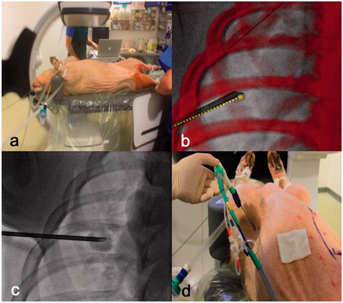
Tumor-mimic lesions (TML) were placed into the lungs of the anesthetized pigs using a technique adapted from Planché et al. [Citation12]. Muscle was extracted from the thigh of the already anesthetized pig and processed into a paste with iodinated contrast (Visipaque 350®, GE HealthCare, US) at a fixed ratio of 3:1. The paste was injected under fluoroscopic guidance (Discovery, IGS 740, GE Healthcare, US) with or without trajectory planning with cone-beam computer tomography (CBCT) into the upper and lower lobes of the lungs bilaterally (4 lesions in total) through a 13 G cementoplasty needle (Vertebroplasty Coaxial Access Set; Cook medical, Bloomington, IN) (). The trajectory planning software used was TrackVision®(GE Healthcare, Chalfont St Giles, UK). TMLs were placed centrally within the lung parenchyma, away from the pleural and heart.
Figure 1. Experiment setting and workflow. (a) This figure shows the installation of the pig under general anesthesia. Tumor mimic lesion injection to create 1, 2 or 3 cm tumor with (b) or without (c) guidance software. Ablation probe was inserted through the same coaxial canula (d) facilitating the accurate targeting of the tumors.
Following initial injection of the TML paste, CBCT acquisition was performed to measure their size. When necessary, adjustments with additional injection of TML paste were made. The TMLs were created to have maximum diameters of 1, 2 or 3 cm. Following TML creation, lesions within each size group were randomized to undergo MWA with either pulsed or continuous energy delivery [Citation13]. If a pneumothorax occurred, a chest tube was placed to minimize the effect of atelectasis on the rest of the procedure. In total, 44 TMLs were created (4 in each pig), though 1 TML was excluded from the study as it was above size criteria (4 cm).
Ablation procedure
MWA was performed immediately after satisfactory creation of TML. For all ablations, a single MWA antenna (APK 14-20, 14 G, 20 cm, Amica®, HS Medical, Aprilia, Italy with an active heating zone of 2.5 cm) was inserted into the TML under fluoroscopic and CBCT guidance, through the existing 13 G needle (used to obtain TML).
The ablation was performed using a microwave generator with a maximum power of 140 W at 2.45Ghz (Amica, HS medical, Aprilia, Italy) through the single antenna. A second ablation was not allowed.
Power settings and ablation time were determined based on the size of the TML, according to the manufacturer’s instructions for use for treatment of liver lesions [Citation14–16]. With respect to energy delivery, continuous-mode (CM) consists of continuous homogenous energy delivery throughout the entire ablation time. With pulse-mode (PM) energy delivery was intermittent with higher peak energy in comparison to with CM. Treatment algorithms were as follows: for TML of 1 cm, 2 cm and 3 cm, the power (Watts) and duration (minutes) were 40 W × 3min, 50 W × 5min and 60 W × 10min for CM and 60 W × 3min, 100 W × 5mins and 125 W × 10mins for PM respectively.
Following ablation, the antennae was gently removed, and either a 6 cm straight suture needle or a piece of 0.35″ hydrophilic guidewire was inserted into the TML under fluoroscopic guidance along the ablation tract, through the existing 13 G needle. This provided a physical marker along the long axis of the ablation for orientation purposes during gross pathological examination (Supplemental data Figure 1). A post-procedure CBCT was then performed to assess the ablation zone and to check for immediate complications. The pigs were euthanized whilst still under general anesthesia shortly after the final post-ablation CBCT and marker insertion (approximately 5 min). The lungs were harvested en-block within 30 min of euthanization.
Imaging and data analysis
The ablation zone was evaluated on multiplanar reconstructions with lung window settings (WW: 1500HU; WL: −500HU) (). Two of the study’s lead researchers (LT/CT) who were blinded to the ablation mode (PM or CM) conducted the measurements independently. Measurements were made using an electronic caliper on Osirix MD, V10 (Pixmeo®, Geneva, Switzerland). For the purposes of measurement, the outer most part of the immediate post-ablation ground-glass lung parenchymal changes (but within the hyperdense rim) visible on CBCT was considered to be the limit of the ablation zone on imaging. TML location, size, surrounding ground glass opacification with dense rim, pleural effusion and air in the pleural cavity or in soft tissues were also analyzed for each ablation.
Figure 2. Imaging evaluation of ablation volumes. This figure shows how measurements on immediate post ablation CBCT imaging were performed by 2 radiologists. The line on the top show the coaxial canula placement before MWA probe insertion. The bottom line shows the measurement on post ablation CBCT imaging on multiplanar reconstructions. D1 (in black) : long axis; D2 (in grey) : orthogonal cranio-caudal measure; D3 (dotted line) : orthogonal lateral measure.
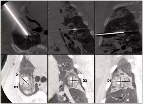
Three orthogonal measurements were obtained: D1 was the length along of the probe axis (marked with the suture needle placed at the end of the ablation), D2 and D3 were perpendicular to D1 in a cranio-caudal and axial plane respectively. The ablation zone considered as an ellipsoid and the volume (V) was calculated with the formula V = 4/3 × π × (R1 × R2× R3) where R1 = D1/2; R2 = D2/2; R3 = D3/2. The sphericity index (SI) of the ablation zone was calculated dividing the longest axis by the shortest axis. Sphericity of 1 corresponds to a perfect sphere. A SI above 1 corresponded to an elongated shape along the MWA probe axis, and a SI below correspond to a lesion elongated perpendicular to the MWA probe axis.
Pathology evaluation
Lung specimens were prepared for macroscopic pathology ensuring it was dissected along the plain of the D1 axis and a perpendicular axis before being were placed in a 10% formalin and sent to the pathologist. The pathologist performed gross assessment of the ablation zones and as well as evaluated for the presence of adjacent pulmonary (i.e., mains vessels and airways) and extrapulmonary (i.e., heart, diaphragm, thoracic wall) structures.
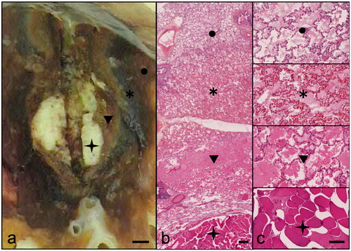
The pathologist was blinded to the energy delivery mode (CM or PM). Due to the method of specimen preparation, i.e., lung and TML cut along the plane of D1 and perpendicular axis, accurate direct measurement of D2 or D3 on pathological specimen was not possible. Therefore, for the purposes of this study, we approximated the length of D2 to be equivalent to D3. Measurements of the ablation margins were determined on macroscopic examination and confirmed on microscopic analysis. Specimens were subject to Hematoxylin Eosin Staining (HES) for microscopic analysis. Areas of necrosis and inflammation were evaluated with on microscopy to confirm the ablation margins ().
Figure 3. Pathological assessment of ablation zones. This figure is a representative example of pathological findings after MWA of tumor mimic lesions. Macroscopic analysis (a: scale bar 2mm) shows concentric layers centered by the TML (star), a clear area (arrowhead) and a dark zone (asterisk) surrounded by edema (circle). Hematoxylin Eosin staining at ×10 (b: scale bar 200μm) and ×100 (c: scale bar 50μm) present coagulation necrosis in the clear zone (arrowhead) and hemorrhagic alterations in the dark zone (asterisk). The surrounding lung tissue shows reactional alveolar edema (circle). The limits of the ablation zone are typically at the internal interface of the dark zone (hemorrhagic rim).
Data and statistical analysis
Data regarding treatment algorithm including energy, delivery mode, duration of treatment and power used were collected.
D1, D2, D3 and volume of the MWA zone measured on both post-ablation CBCT acquisition and pathology were compared using an unpaired Student’s t-test. The diameters D2 and D3 were compared on CBCT measurements using a matched-paired t-test. Coefficient of variation (CV) was used to evaluate the reproducibility of the ablation volume for lesions of the same dimension treated with the same algorithm. Inter-observer reliability of the measures of the ablation zones were assessed using the Bland-Altman method and Cohen’s weighted kappa (wκ).
A 5 mm tumor-free margin being considered as a technical success [Citation17–20]. Procedure-related complications were collected and classified according to the Common Terminology Criteria for Adverse Events (CTCAE version 5.0).
Statistical analysis was performed using GraphPad Prism Version 8.0. A p-value of less than 0.05 was considered significant.
Results
A total of 43 TMLs were successfully created to size criteria. One TML measured 4 cm and was excluded from the study. The number of TMLs (n = CM/PM) according to size (maximum diameter) is as follows: 1 cm (n = 7/7), 2 cm (n = 10/8), 3 cm (n = 6/5). Mean TML size, before ablation, was: D1:19.4 ± 6 .2 mm; D2: 16.3 ± 4.9 mm; and D3: 16.7 mm ± 5.3 mm.
Imaging evaluation of ablation zone
Ablation zone size according to each protocol and TML size are summarized in .
Table 1. Imaging and histopathologic evaluation of lung MWA ablation zones according to treatment algorithms for tumor mimic lesions.
Technical success was obtained for all TML ablations. Inter-observer correlation for measurements of the ablation zone on CBCT was excellent (wκ = 0.91).
Radiology-pathology correlation
The volume of the ablation zone was significantly smaller on pathologic specimens when compared to CBCT (mean percentage difference in length: − 30.4% 0.15%) as expected due to postmortem deflation of the lungs and further contraction by approximately 10%, following formalin fixation. A significant linear correlation between immediate post-operative CBCT acquisition and pathological measurements was found (r = 0.79
0.1, Deming: p < 0.0001).
Continuous versus pulsed mode
Ablation volumes and dimensions as measured on CBCT for PM and CM according the TML size are presented in and . For ablation of 2 and 3 cm TMLs, no statistical difference was found for ablation zone volume (p = 0.38 and p = 0.38) or the sphericity index (p = 0.14 and p = 0.13). For 1 cm TMLs, PM ablation was significantly smaller (p = 0.009).
Figure 4. This figure shows the volume of ablation for tumor-mimic lesions of increasing diameters, performed with continuous and pulsed mode. No significant difference was found in between pulsed and Continuous modes for ablation volume nor for index sphericity, except for 1 cm TMLs: PM ablation was significantly smaller (p = 0.009). p values are calculated using unpaired student’s t test.
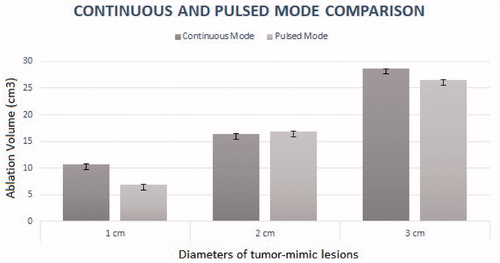
Table 2. Continuous and pulsed mode comparison.
Reproducibility of ablation zone
With CM ablation, CBCT demonstrated a coefficient of variation of 30.5%, 31.5% and 16.2% for ablations performed for 1 cm, 2 cm and 3 cm TMLs respectively. With PM ablation, CBCT demonstrated a coefficient of variation of 19.7%, 46%, 34.5% for lesion of 1 cm, 2 cm and 3 cm respectively. There is a moderate reproducibility rate.
Complications
Complications occurred during 5 ablations, including: 3 pneumothoraxes not immediately life-threatening but requiring chest drain placement to resolve (CTCAE Grade 3); and 2 intra-alveolar hemorrhage events, which did not require further treatment (CTCAE Grade 2). At necropsy, no major injuries of the surroundings organs were observed. No per-operative death occurred.
Discussion
There is a shared consensus that at current there remains a paucity of data to guide the design of energy delivery protocols for MWA in the lung, which is vital to ensure treatment success [Citation1,Citation5]. In addition, much of the available experimental data is derived from ex vivo liver ablation models. However, in vivo and ex vivo ablation performances for human tumors differ significantly because of thermal diffusion or negative heat flux caused by blood perfusion [Citation20]. Different devices can also produce different sphericity indices and ablations zones [Citation20].
In this study, using an in vivo lung TML model, we evaluated MWA ablation protocols derived from manufacturers recommended energy delivery protocols for liver ablation in the lung. We demonstrated that with the specific device and protocols used, MWA produced ablation areas large enough to treat lesions up to 3 cm in diameter within 10 min of ablation time both with CM and PM energy delivery, though the reproducibility of ablation volume was moderate.
Interestingly, previous literature had purported that PM energy delivery in MWA may increase ablation sphericity. However, we found that both CM and PM resulted in ellipsoid ablation patterns along the needle axis with no significant difference in SI. With respect to volume, a significant difference was found only for TMLs of 1 cm, where there was a significantly smaller ablation volume with PM when compared to CM. Whilst no statistical difference was found for the other sized TMLs, we noted a trend toward smaller ablation volumes using pulsed mode for all algorithms. Although the reason for this is not yet ascertained, we postulate that it may be due to thermodynamic mechanisms of the lung parenchyma. Sudden variation of thermal conductivity between the tumor and the surrounding parenchyma may affect heat progression when energy delivery is interrupted in PM. Further laboratory studies including mathematical simulation protocols are on-going to better understand these phenomena. Furthermore, tissue changes caused by thermal delivery, such as charring and desiccation also modify electrical resistance in tissue, thus possibly further hindering the expansion of the ablation zone. The high electrical resistance within ventilated lung parenchyma and the ablation-induced tissue inhomogeneity make the expansion of the ablation zone particularly reliant on thermal conduction, especially at its periphery [Citation10,Citation21,Citation22]. Within current clinical practice of MWA in the liver, to overcome the issue of limited sphericity, multiples antennas have been used to shape the ablation zone to create nearly spherical ablation zones. Further in vivo research is required to determine to optimal approach to ablation in the lung, whether it is by placing more antennae and/or energy delivery [Citation23].
There was a significantly positive correlation between measurements of the ablation zone on immediate post-ablation CBCT and on pathological analysis. This supports the use of immediate post-ablation CBCT to evaluate ablation adequacy, which can guide the operator to perform additional ablation if necessary, to ensure success. We feel this is particularly crucial, given that in this study we found only moderate reproducibility of ablation volume.
Another interesting observation was that regardless of energy delivery protocol and TML size, the cranio-caudal ablation diameter (D2) was always the shortest. Length of D2 was also significantly shorter than D3 (p < 0.001) even though in theory energy deliver should be equivalent in these two axes. Whilst the reasons for this are not clear, we believe the shorter D2 ablation length is likely due to respiratory movement. This may have several implications on clinical practice. First, it suggests that MWA antennae placement in the cranio-caudal plane may need to be particularly accurate to ensure adequate ablation. In addition, adjunctive measures to minimize tidal volume and hence reduce respiratory motion, such as high frequency oscillatory ventilation, may in theory provide some benefits in terms of allowing a better ablation size in the cranio-caudal axis [Citation24].
Future studies to evaluate this would be beneficial.
Regarding complications, our results are similar to those obtained by to others studies previously published [Citation25,Citation26], and the 27.3% CTCAE grade 3 complications are acceptable considering that we performed 4 ablations per animal.
Our study presents some limitations. First, the number of TMLs in each experimental group (according to energy delivery and size) was small. Furthermore, there was some variability in TMLs size and location. To minimize this variability, we tried to create the TML centrally within the lung parenchyma and sufficiently far away from the pleura and from hilum. All TMLs were also created by the same operator, using a standardized technique involving injecting the same quantity of mixture for a given tumor size. With respect to MWA antenna placement, typically, in clinical practice, conventional CT is used. However, due to the setup in this experimentation study, placement was under fluoroscopy with additional CBCT and navigational software to overcome this issue and ensure accurate placement.
Finally, due to the lack of availability of large animal ‘real’ tumor model, we created an in vivo experimental alternative by placing the TML directly into the lung. We acknowledge that the TML does not reflect perfectly real tumor properties in that they do may not share the same biological properties such as vascularity or permittivity. This raises two issues. First, the TML and surrounding lung may not respond to the energy delivered by MWA in the same way as it does for real lung tumors. Second, in our TML, there were no tumor cells in the ablation margin around the main lesion, though there may be in a real tumor. As such it although the ablation zones in our experimental model were sufficient, this may not be the case in on a real patient. Acknowledging this limitation, we aimed to be as conservative as possible when taking measurements of ablation zones, both on radiological imaging, and on pathological specimens.
Conclusion
In conclusion, this study provides additional information that may guide the design of energy delivery protocols for MWA in the lung. The study demonstrated that apart from for small lesions (1 cm), there was no difference in ablation volume and sphericity with CM or PM energy delivery for MWA in the lung. Ablation volumes were only moderately reproducible, suggesting the need to use post-ablation CBCT to ensure ablation adequacy.
Supplemental Material
Download PDF (436.7 KB)Disclosure statement
None of the authors has related conflict of interest. ICMJE will be submitted separately.
Additional information
Funding
References
- Smith SL, Jennings PE. Lung radiofrequency and microwave ablation: a review of indications, techniques and post-procedural imaging appearances. Br J Radiol. 2015;88(1046):20140598.
- de Baère T, Aupérin A, Deschamps F, et al. Radiofrequency ablation is a valid treatment option for lung metastases: experience in 566 patients with 1037 metastases. Ann Oncol. 2015;26(5):987–991.
- Lencioni R, Crocetti L, Cioni R, et al. Response to radiofrequency ablation of pulmonary tumours: a prospective, intention-to-treat, multicentre clinical trial (the RAPTURE study). Lancet Oncol. 2008;9(7):621–628.
- Dupuy DE, Zagoria RJ, Akerley W, et al. Percutaneous radiofrequency ablation of malignancies in the lung. AJR Am J Roentgenol. 2000;174(1):57–59.
- Skinner MG, Iizuka MN, Kolios MC, et al. A theoretical comparison of energy sources–microwave, ultrasound and laser–for interstitial thermal therapy. Phys Med Biol. 1998;43(12):3535–3547.
- Lu DSK, Yu NC, Raman SS, et al. Radiofrequency ablation of hepatocellular carcinoma: treatment success as defined by histologic examination of the explanted liver. Radiology. 2005;234(3):954–960.
- Louis Hinshaw J, Lubner MG, Ziemlewicz TJ, et al. Percutaneous tumor ablation tools: microwave, radiofrequency, or cryoablation – what should you use and why? Radiographics. 2014;34(5):1344–1362.
- Sidoff L, Dupuy DE. Clinical experiences with microwave thermal ablation of lung malignancies. Int J Hyperthermia. 2017;33(1):25–33.
- Shock SA, Meredith K, Warner TF, et al. Microwave ablation with loop antenna: in vivo porcine liver model. Radiology. 2004;231(1):143–149.
- Vogl TJ, Nour-Eldin N-E, Albrecht MH, et al. Thermal ablation of lung tumors: focus on microwave ablation. Rofo. 2017;189(9):828–843.
- Bedoya M, Del Rio AM, Chiang J, et al. Microwave ablation energy delivery: influence of power pulsing on ablation results in an ex vivo and in vivo liver model. Med Phys. 2014;41(12):123301.
- Planché O, Teriitehau C, Boudabous S, et al. In vivo evaluation of lung microwave ablation in a porcine tumor mimic model. Cardiovasc Intervent Radiol. 2013;36(1):221–228.
- Al-Hakim RA, Abtin FG, Genshaft SJ, et al. Defining new metrics in microwave ablation of pulmonary tumors: ablation work and ablation resistance score. J. Vasc. Interv. Radiol. 2016;27(9):1380–1386.
- Hernández JI, Cepeda MFJ, Valdés F, et al. Microwave ablation: state-of-the-art review. Onco Targets Ther. 2015;8:1627–1632.
- Ruiter SJS, Heerink WJ, de Jong KP. Liver microwave ablation: a systematic review of various FDA-approved systems. Eur Radiol. 2019;29(8):4026–4035.
- Vogl TJ, Nour-Eldin N-E, Hammerstingl RM, et al. Microwave ablation (MWA): basics, technique and results in primary and metastatic liver neoplasms – review article. Rofo. 2017;189(11):1055–1066.
- Kurilova I, Gonzalez-Aguirre A, Beets-Tan RG, et al. Microwave ablation in the management of colorectal cancer pulmonary metastases. Cardiovasc Intervent Radiol. 2018;41(10):1530–1544.
- Hoffmann COM, Rosenberg C, Linder A, et al. Residual tumor after laser ablation of human non-small-cell lung cancer demonstrated by ex vivo staining: correlation with invasive temperature measurements. Magn Reson Mater Phy. 2012;25(1):63–74.
- Sofocleous CT, Garg SK, Cohen P, et al. Ki 67 is an independent predictive biomarker of cancer specific and local recurrence-free survival after lung tumor ablation. Ann Surg Oncol. 2013;20 Suppl 3:S676–S683.
- Clasen S, Krober SM, Kosan B, et al. Pathomorphologic evaluation of pulmonary radiofrequency ablation: proof of cell death is characterized by DNA fragmentation and apoptotic bodies. Cancer. 2008;113(11):3121–3129.
- Zhang T-Q, Huang S-M, Gu Y-K, et al. Sequential and simultaneous 4-antenna microwave ablation in an ex vivo bovine liver model. Cardiovasc Intervent Radiol. 2019;42(10):1466–1474.
- Harari CM, Magagna M, Bedoya M, et al. Microwave ablation: comparison of simultaneous and sequential activation of multiple antennas in liver model systems. Radiology. 2016;278(1):95–103.
- Cazzato RL, De Marini P, Leclerc L, et al. Large nearly spherical ablation zones are achieved with simultaneous multi-antenna microwave ablation applied to treat liver tumours. Eur Radiol. 2020;30(2):971–975.
- Galmén K, Harbut P, Freedman J, et al. High frequency jet ventilation for motion management during ablation procedures, a narrative review. Acta Anaesthesiol Scand. 2017;61(9):1066–1074.
- Grieco CA, Simon CJ, Mayo-Smith WW, et al. Percutaneous image-guided thermal ablation and radiation therapy: outcomes of combined treatment for 41 patients with inoperable stage I/II non-small-cell lung cancer. J Vasc Interv Radiol. 2006;17(7):1117–1124.
- Splatt AM, Steinke K. Major complications of high-energy microwave ablation for percutaneous CT-guided treatment of lung malignancies: single-centre experience after 4 years. J Med Imaging Radiat Oncol. 2015;59:609–616.