
 ?Mathematical formulae have been encoded as MathML and are displayed in this HTML version using MathJax in order to improve their display. Uncheck the box to turn MathJax off. This feature requires Javascript. Click on a formula to zoom.
Abstract
Purpose
Stellate ganglion (SG) block by thermal radiofrequency ablation (RFA) is frequently conducted as a therapeutic intervention for sympathetic-maintained and neuropathic pain syndromes. RFA’s partial lack of effectiveness could be partly due to the ablation zone (AZ) not completely covering the SG section and therefore preventing the ‘cutting’ of the afferent pathways. Our objective was to build a theoretical model to conduct computer simulations to assess the effect of the electrode position relative to the SG.
Methods
A three-dimensional model was built including the SG and adjacent tissues (vertebrae C7-T1-T2, trachea, carotid artery and vertebral artery). RFA (90-s, 80 °C) was simulated considering a 22 G-5 mm electrode. The AZ was computed using the 50 °C isotherm.
Results
An electrode displacement of 2 mm in any direction from the optimal position (centered on the SG) meant that the AZ did not fully cover the SG section. Likewise, SG size considerably affected the RFA effectiveness since the AZ fully covered the section of small but not large SGs.
Conclusions
The findings suggest that the currently used SG RFA settings (i.e., 22 G-5 mm electrode, 90-s, 80 °C) may not be appropriate due to their inability to achieve an AZ that fully covers the SG cross section under certain circumstances, such as a large SG and non-optimal positioning of the RF electrode with respect to the SG center.
1. Introduction
The stellate ganglion (SG), also known as the cervico thoracic ganglion, is part of the sympathetic nervous system. The SG is a bilateral structure formed by the fusion of inferior cervical and first thoracic sympathetic ganglia in 80% of cases [Citation1], providing sympathetic supply to the head, neck, and upper limbs [Citation2] (see ). SG blockade by means of local anesthetics has been conducted as a therapeutic intervention for a wide variety of sympathetic-maintained [Citation3] and neuropathic pain syndromes, e.g., for complex regional pain syndrome [Citation1], ventricular arrhythmias [Citation4], cerebral vasoconstriction [Citation5], and cancer pain [Citation6]. Different techniques have been used to block the SG, including local anesthetics, steroids and chemical neurolytic agents (3% phenol in saline, ethanol). Since repeated blocks are sometimes required for patients in whom the effective period is short [Citation3], radiofrequency (RF) ablation (RFA) has been suggested as an alternative to induce irreversible nerve degeneration (i.e., heat-induced neurolysis) and is expected to have a more prolonged effect [Citation7–9]. RFA uses RF power (∼500 kHz) to selectively create a zone of coagulative necrosis in the ablation zone (AZ). In fact, percutaneous RFA of SG may be regarded as a continuous regional sympathetic block with long-term efficiency, improved safety, more precise localization, and less morbidity and mortality than surgical sympathectomy [Citation10].
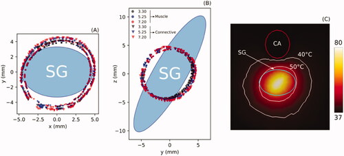
Fgure 1. (A) Overview of anatomy of the right stellate ganglion (SG) and position of the RF needle used to thermally achieve a block. (B) Detail of the RF needle tip positioned in the ganglion area. The objective is that the RF-induced ablation zone causes neurolysis in the section of the ganglionic chain in order to ‘cut’ the neural pathways.
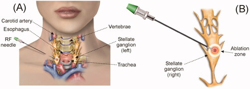
Although there is no scientific consensus on what the AZ should look like in the case of SG ablation, the first studies on sympathetic denervation already pointed to the need to interrupt the pathways [Citation11], i.e., achieve ‘complete cutting’ of the nerve pathway, rather than completely destroying the SG (as in tumor ablation), i.e., to create as large a volume of AZ as possible. In practical terms, ‘complete cutting’ would imply achieving an AZ covering 100% of the SG section, since the nerve fibers that constitute the sympathetic chain run laterally to the vertebral bodies (craneo-caudal direction) [Citation12], and hence transversely to the SG section. This reasoning is surely relevant in the context of assessing the efficacy of RFA for SG blockade. To create the AZ, a needlelike RF electrode is inserted following a step-by-step placement approach until the needle tip is correctly located on the target site, i.e., closest to the SG.
Although multiple imaging tools such as magnetic resonance imaging and computed tomography scans have been used to guide the SG block, ultrasound and fluoroscopy are used more often in clinical practice and in some cases may be combined. While fluoroscopy delineates the C6/C7 bony landmarks, the ultrasound guide is the gold standard for RFA of SG since it also shows non-bony (i.e., soft) structures such as vessels, nerves and muscles. However, it should be noted that SG cannot be consistently visualized by any technique, and in fact although a neural structure can be seen inside the longus colli muscle, and frequently on its anterior fascial surface, its location is calculated by identifying the position of other tissues: the carotid artery and prevertebral fascia (anterior); the longus colli muscle, C7 transverse process, neck of first rib, vascular network of small vessels (posterior); longus colli muscle (medial); and vertebral artery, and the C7 or C8 root (lateral) [Citation13]. Despite this wide range of imaging techniques, the SG percutaneous approach is not free of risks due to neighboring neurovascular structures such as the vertebral artery, subclavian artery, pleura, phrenic nerve, recurrent laryngeal nerve, and C8-T1 anterior divisions.
The frequent lack of effectiveness of some RFA of SG settings could be due in part to the AZ not completely covering the SG section and thus not cutting off the afferent pathways for two reasons: (1) the conventional settings used (power, time, target temperature, electrode size) are not appropriate for ablation of an average-sized SG (i.e., difference between sizes of the SG and the ablation zone), and (2) the electrode is not in the correct position to ablate the SG. Our objective was thus to build a theoretical model including both the ganglion and its adjacent structures and conduct computer simulations to estimate the size of the AZ after RFA of SG. To our knowledge, this is the first computer model for RFA of SG designed to study the effect of SG size and electrode position on the AZ volume, an extremely complex question to answer from the data generated by pre-clinical (or clinical) experiments.
2. Methods
2.1. Model building
A three-dimensional model was built on the basis of files from the Virtual Population V2.0, especially those from a 34-year old male (Duke) (see ) [Citation14]. This human model consists of 22 files in stl format obtained using Whole-body Magnetic Resonance Imaging (WB-MRI) according to a protocol presented in [Citation14]. We used two of the 22 files that detail the non-intersecting surfaces of different tissues and organs: Bone.stl and Respiratory_system.stl. After ‘cutting’ the C7-T1-T2 vertebrae from the Bone.stl file and the corresponding region of the trachea from the Respiratory_system.stl file, we pre-processed the meshes to simplify the model. This procedure of trimming and simplifying was carried out using MeshLab Visual Computing Lab software (http://meshlab.sourceforgel.net) [Citation15]. These two simplified surfaces were imported into the meshing software Gmsh [Citation16] and used to create and remesh the respective volumes with the routines described in [Citation17]. Paraview software was used to plot the results [Citation18].
Figure 2. (A and B) 3D model based on imaging. (C and D) Cylindrical volume including the right stellate ganglion (SG) and the tissues around which were expected to be relevant in the context of the RFA due their proximity.
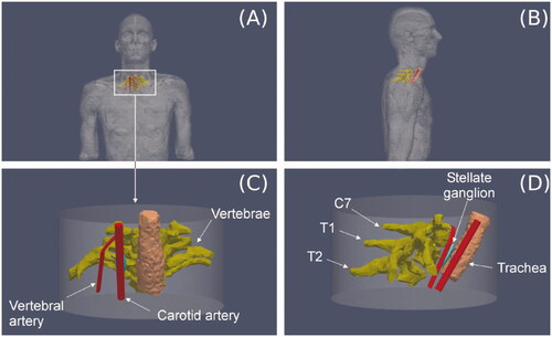
Since the files of the Virtual Population V2.0 do not include vessels, we had to include them in the model as simple geometric volumes (cylinders in this case), which facilitated the parameterization of diameters and distances to the SG, such as to the active electrode and diameter vessel. Finally, a cylinder (80 mm height, 150 mm diameter) representing the neck and encompassing all other structures was also built-in using Gmsh: SG and relevant nearby adjacent tissues, in particular three consecutive vertebrae (C7-T1-T2) and a segment of the trachea, carotid artery and vertebral artery (). The cylinder’s outer size and the mesh size were verified by a convergence test (see Section 2.7). All these structures were assumed to be surrounded by connective or muscular tissue, with a continuity condition based on node sharing. We considered an RF electrode of 22 G (0.72 mm diameter) and 5 mm active tip (including a 2-mm beveled zone). The metal electrode was attached to a 10-mm plastic segment). This electrode diameter is normally used to block the SG in thermal ablation [Citation1,Citation7,Citation8].
The SG was simplified as an ellipsoid with craniocaudal (CC) length of 20.3 mm (i.e., the longest axis), laterolateral (LL) length of 7.6 mm and anteroposterior (AP) length of 4.3 mm. These were the mean values of those reported in Chaudhry et al. [Citation2] which summarizes the values reported in previous anatomical studies. The carotid artery was modeled as a 6.3 mm diameter blood-filled cylindrical structure. This diameter value is within the values measured by Krejza et al. [Citation19] for men (6.52 mm) and women (6.10 mm) just 2 cm below the carotid bifurcation. This position does not correspond with the SG position, but it is a bit closer to the cranium. For this reason, we conducted our own ultrasound-based measurements on 10 patients to assess intra-individual variations of the carotid artery diameter at two different points: (1) just 2 cm below the carotid bifurcation and (2) the C7 level (area of interest in terms of RFA of SG). Since we did not find any variations, we assumed that the carotid diameter near the SG was around those values.
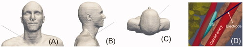
The trachea was considered to be air-filled and its wall was ignored. The distances between the SG center and adjacent tissues were taken from our own ultrasound-based measurements (see ) from 10 patients in the RFA supine position: neck turned to the contralateral position with a pillow under the scapula ipsilateral to the puncture and with the arm outstretched toward the patient's feet. The sample consisted of 5 women and 5 men, 37 ± 12 years, weight 69 ± 15 kg and height 169 ± 8 cm. The values found in relation to the right SG were 4.0 ± 1.2 mm to carotid artery, 4.5 ± 1.3 mm to vertebra, 14.1 ± 3.9 mm to trachea, and 11.6 ± 4.2 mm to vertebral artery. From these reference values, we positioned the SG as shown in . The electrode was considered to be inserted in the SG (see ) in a position equivalent to an approximation in which the electrode reaches the longus colli.
Figure 3. (A and C) Section plane showing the relative distances to stellate ganglion (SG) from the adjacent tissues. These distances were obtained from on ultrasound-based measurements conducted on 10 patients. B: Discretized domain of the area in which the RF applicator tip is inserted into the SG. (D) Example of ultrasound image showing the relevant structures around SG (white arrow). V: vertebral artery; CA: carotid artery; SCM: sternocleidomastoid muscle; LC: longus colli muscle; Thy: thyroid; Tr: trachea; VE: vertebra.
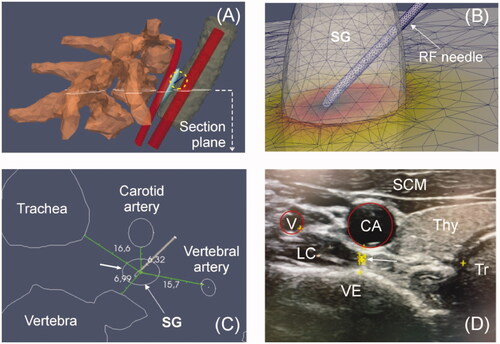
Figure 4. (A–C): Orientation of the RF applicator in the insertion toward the SG. (D): Detail of the RF applicator entering inside the SG.
2.2. Governing equations
The model was based on an electric problem which was solved numerically by the Finite Element Method implemented on FEniCS [Citation20]. The governing equation for the thermal problem was the bioheat equation [Citation21]:
(1)
(1)
where ρ is density (kg/m3), c specific heat (J/kg·K), T temperature (°C), t time (s), k thermal conductivity (W/m·K), q the heat source caused by RF power (W/m3), Qp the heat loss caused by blood perfusion (W/m3) and Qm the metabolic heat generation (W/m3). Qm was not considered because it is negligible in comparison to the other terms [Citation21]. Qp was computed as follows:
(2)
(2)
where ρb is blood density (kg/m3), cb its heat capacity (J/Kg·K), Tb its temperature (37 °C), and ωb the blood perfusion coefficient (s–1). In all cases the value of ωb was set to zero at the points that reached a temperature of 50 °C, which allowed modeling the loss of blood perfusion due to the thermal destruction of the tissue. Since tissue temperatures always remained below 100 °C it was not necessary to implement the phase change phenomenon.
At the RF frequencies (∼500 kHz) used in RF heating, and over the distance of interest, the biological medium can be considered almost totally resistive, since the displacement currents are much less important than the conduction currents. A quasi-static approach to solving the electrical problem was therefore possible [Citation22]. The distributed heat source q is then given by q = σ|E|2, where |E| is the magnitude of the vector electric field (V/m) and σ the electrical conductivity (S/m). E = –∇Ф is calculated from the gradient of the voltage Φ(V), which, in the absence of internal electric sources, satisfies ∇·(σ∇Ф) = 0.
2.3. Model properties
shows the physical characteristics considered for the tissues (obtained from the IT’IS Foundation database [Citation23]) and RF electrode (taken from Pérez et al. [Citation24]). Although no specific data are available on SG, the sensory ganglia are known to comprise the soma of sensory neurons, most of which appear pale and foamy after H&E staining due to the presence of myelinated nerve fibers. We considered that the SG could have homogeneous properties equivalent to brain tissue (specifically white matter) due to the presence of myelin. Since the ganglia are surrounded by a dense connective tissue capsule, we considered a 1 mm thickness connective tissue layer surrounding the SG. The properties for vertebrae were considered to be the mean values between the cortical and trabecular bone.
Table 1. Physical characteristics of tissues and materials employed in computer model [Citation23,Citation24].
Prior to RFA of the SG, a local anesthetic is injected to alleviate pain during thermal ablation (e.g., 1% lidocaine HCl is used in our hospital). This anesthetic also receives the benefit of the vasodilator and neuro-protective effects of lidocaine if unwanted neurovascular contact occurs during needle insertion [Citation7]. We conducted an additional set of simulations to assess the effect of this anesthesic solution could alter SG electrical conductivity and consequently AZ volume. To do this, we assumed an amount of 1 ml of 1% lidocaine HCl (i.e., 10 mg/mL) whose electrical conductivity at 37 °C can be estimated from [Citation25], obtaining a value of 0.4 S/m, which is very similar to the tissues around the SG, but higher than assumed for the SG (∼0.1 S/m). Due to the tiny volume of the SG (∼347 mm3) compared to the volume occupied by 1 ml anesthetic solution (1,000 mm3) we assumed that the injection of the anesthesic solution would change the electrical conductivity to 0.4 S/m.
2.4. Boundary conditions
We simulated a 90-s constant temperature RFA with a target of 80 °C (the temperature sensor was assumed to be exactly in the middle of the bevel) by modifying the applied power in the active electrode step by step as heating progressed. The dispersive electrode was assumed to be placed on the thigh and was modeled as an electrical condition of 0 V at the bottom of the model.
All the outer surfaces were fixed to 37 °C. A thermal condition of forced convection (due to the passage of air) was imposed on the inner surface of the trachea, with a coefficient value h = 8 W/m2·°C, which is around the average values estimated in the upper airway [Citation26]. The temperature inside the carotid artery was set at 37 °C (Dirichlet boundary condition). Although this condition implicitly assumes considerable cooling power from the internal carotid flow and could hence underestimate the AZ volume, computer simulations considering a very short SG–carotid distance only showed an effect on the 40 °C isotherm, but not on the lesion contour (assessed by the 50 °C isotherm, see below). In fact, although the nominal value of the SG-carotid artery distance was 4.02 mm (taken from our ultrasound-based measurements), we conducted a preliminary set of simulations varying this parameter with a slightly lower value (3.3 mm) to another large enough to consider a negligible thermal effect (7.2 mm) and also changing the type of tissue surrounding all the structures (muscular vs. connective).
2.5. Effect of the electrode position
We assessed the effect of positioning the electrode tip ± 2 mm from each axis (x, y and z), which mimics a frequent clinical situation. In this set of simulations we were especially interested in assessing the spatial matching of the AZ with SG volume. We think that this spatial overlapping could be related to the effectiveness of the SG block, since the clinical outcome could be equivalent to achieving an ablation zone capable of cutting off the afferent pathways at the SG level, i.e., an ablation zone occupying the entire SG section.
2.6. Assessment of AZ volume and clinical outcome
The lethal isotherm for tissues subjected to several-minutes of RF heating is assumed to be between 55 and 56 °C [Citation27]. However, for neural tissues, such as the SG, the 45–50 °C isotherm is considered to be critical and to define the heat lesion volume [Citation28], so that the AZ contour was computed using the 50 °C isotherm.
In order to assess the effect of the SG–electrode position on the efficacy of the RFA, we analyzed the cases in which the AZ was able and unable to ‘section’ the entire transverse SG section (which would represent a successful block). We also calculated the ablated SG volume (VA) as a percentage of its total volume (VTotal), which could also be related to the effectiveness of the SG block. Note that currently it is not clear whether the entire SG has to be within the ablation zone to achieve a clinical effect.
In order to assess how different the results would be with respect to the size of the node, we conducted two additional sets of simulations: (1) varying only one of the lengths to its maximum–minimum values reported by Chaudhry et al. [Citation2] (6.3 – 10.0 mm for LL, 18.5 – 25.0 mm for CC and 3.9 – 5.0 mm for AP), and (2) also considering the minimum and maximum lengths to model the smallest and biggest SG, respectively. summarizes the simulations carried out and the specific conditions.
Table 2. Summary of the computer simulations.
3. Results
Firstly, the model was verified in terms of mesh size, outer dimensions and time step. The minimum grid size was around the electrode tip (0.2 mm), the step time was 0.1 s and the outer dimensions of the cylindrical prism comprising the model (see ) were a base of 150 mm and 80 mm high. When we considered smaller values for the grid size and time step the maximum temperature reached in the tissue changed by less than 0.2 °C. As the same occurred when greater outer dimension values were considered, these values were considered to be suitable.
shows the AZ boundaries computed from Sets 1 and 2 (see ) aimed at assessing the effect of SG-carotid artery distance (3.3, 5.25 and 7.2 mm) and type of surrounding tissue (C: connective; M: Muscle). The results show that the AZ is ∼1 mm larger in connective tissue than muscle. The effect of the SG-carotid artery distance was almost negligible, with less than 0.5 mm differences in ablation zone size. In other words, the proximity of the carotid artery seems to have little thermal effect on the AZ boundary, even for the shortest distance (3.3 mm), as shown in . The rest of the simulations were thus with the carotid artery at a distance of 4.02 mm (value suggested from our own US measurements) and muscle.
Figure 5. Boundaries of ablation zone computed at the transverse (A) and sagital planes (B) for three distances between stellate ganglion (SG) and carotid artery (3.3, 5.25 and 7.2 mm) and for two types of tissue around the SG: muscle (M) and connective (C). (C): Temperature distribution (scale in °C) around the SG where it can be seen that the ablation zone boundary (50 °C isotherm) is hardly affected by the proximity of the carotid artery (CA), even for a short SG-carotid artery distance of 3.3 mm.
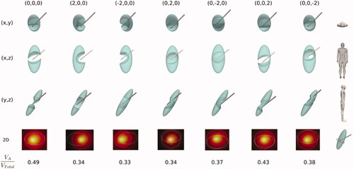
shows the effect of the relative electrode-SG position on the SG ablation volume in the case of SG not affected by the anesthetic solution (i.e., Set 3 in ). While the SG volume is represented by a solid (shown in green), the intersection between the AZ and the SG is represented by subtracting this zone from the SG volume. This facilitates to notice those cases in which the AZ completely occupies the SG cross section can thus be easily seen, suggesting that RFA would be effective. Of the seven cases shown (columns), the first was considered optimal in terms of ‘sectioning’ the entire cross section of the SG (case without relative displacement of the RF electrode, i.e., 0,0,0). In the other six cases, the RF electrode displacement is 2 mm on a single axis in each case (x, y or z). The results show that any of the positions other than the optimal do not achieve ‘thermal section’ of the SG, and therefore would be clinically ineffective. As expected, the ablated/SG volume ratio (VA/VTotal) was maximum for the optimal case (∼50%).
Figure 6. Stellate ganglion volumes (green solid) affected by the ablation volume (subtracted volume) for different cases (columns) of relative position between electrode and SG considering SG unaffected by anesthetic solution. The first column shows the non-displacement case (0,0,0) and represents the optimal case since RFA achieves ‘sectioning’ the entire transverse section of the SG. From there, the following columns show cases where there has been a variation of the electrode position of ± 2 mm in one of the axes. The second last row shows a 2D image of the cross section of the SG (ellipsoidal contour) at the level of the midpoint of the bevel of the electrode tip) where the white line represents the ablation zone. At the bottom the ratio of ablated volume (VA) to SG volume (VTotal) is shown for each case.
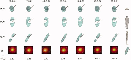
shows the results of Set 4, i.e., the same parameters as in but considering the SG to be affected by the anesthetic solution so that the electrical conductivity is that of the solution itself (see ). These results show how the increased electrical conductivity in the SG area (due to the presence of the anesthetic solution) tends to create a larger AZ, as shown in the values of VA/VTotal, which are all higher than in . This means that in some specific cases, such as when the RF electrode displacement is +2 mm on the z axis, AZ does in fact ‘cut’ the entire SG section, suggesting that a successful ablation is achieved even in these circumstances.
Figure 7. Stellate ganglion volumes (green solid) affected by the ablation volume (subtracted volume) for different cases (columns) of relative position between electrode and SG considering SG affected by anesthetic solution. The first column shows the non-displacement case (0,0,0) and represents the optimal case since RFA is able to ‘section’ the entire transverse SG section. From there, the following columns show cases with a variation of the electrode position of ± 2 mm on one of the axes. The second last row shows a 2D image of the SG cross section (ellipsoidal contour) at the level of the midpoint of the bevel of the electrode tip) where the white line represents the ablation zone. At the bottom the ratio of ablated volume (VA) to SG volume (VTotal) is shown for each case.
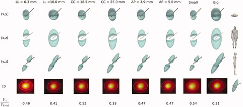
shows the results of Set 5 according to , i.e., the effect of SG size on the ablated volume, with six cases studying variations of one of the lengths (columns) and two additional cases combining the minimum and maximum lengths to mimic the smallest and biggest SG. The results show that LL length is the most critical dimension in terms of the AZ effect on the SG cross section. For instance, the longest LL length (10 mm) is clearly prone to preventing the AZ from covering the entire SG section, while the shortest (6.3 mm) seems to ensure that AZ will ‘cut’ the SG cross section. The other lengths, even when they affect the VA/VTotal ratio, do not seem to greatly influence how the AZ completely ‘cuts’ the cross section of the SG. As expected, the result of combining the minimum and maximum lengths to model the smallest and biggest SG contained an expected accumulated effect, with VA/VTotal ratios of 0.34 and 0.55, respectively, suggesting that ‘cutting’ the SG section is likely in the case of a small SG and highly unlikely with a large SG.
Figure 8. Stellate ganglion volumes (green solid) affected by the ablation volume (subtracted volume) for different cases (columns) of SG size, in particular changing one of the lengths (axes) (LL: laterolateral, CC: craniocaudal, AP: anteroposterior) and combining the minimum and maximum lengths in order to model small and big SG. The second last row shows a 2D image of the SG cross section (ellipsoidal contour) at the level of the midpoint of the bevel of the electrode tip) where the white line represents the ablation zone. At the bottom the ratio of ablated volume (VA) to SG volume (VTotal) is shown for each case.
4. Discussion
This study used a physics-based mechanistic model to assess how AZ adapts to SG volume under different SG sizes and electrode positions. Since this question is too complex to be answered by the data generated through pre-clinical (or clinical) experiments, we conducted an in silico trial based on a 3D model including the relevant tissues and organs around the ablation electrode and computer simulations assuming variable SG size and SG-electrode distance. Although the SG is fusiform and variable in morphology in most cases, and many nerve branches leave-enter at the level of the ganglion itself, it seems reasonable to think that the effectiveness of the technique could be closely related to the ability of the AZ to completely cover the SG cross section. In addition, once this ‘section cut’ has been achieved, the percentage of thermally destroyed SG volume is also possibly related to the effectiveness, assuming that a greater percentage would imply a better outcome. This is possibly due to the fact that in theory a limited or one-sided lesion (e.g., when the SG is only collaterally treated) may only provide a short period of pain relief [Citation29].
The results of Sets 1 and 2 showed that the AZ is ∼1 mm larger in connective tissue than in muscle (see ), which does not seem to be very relevant in the context of the study. Nor does the distance to the carotid artery seem to have much effect, although it must be borne in mind that our model did not solve the fluid dynamics problem in its interior and assumed that its temperature was at 37 °C, which implies a huge ability to evacuate heat from its wall. Future modeling studies to assess the risks of more ‘aggressive’ settings (e.g., larger electrode diameter, higher target temperature, longer duration) should take into account the artery’s internal flow and more realistic modeling of this issue. Despite this limitation, it must be emphasized that this was not our objective, but rather to assess the effect of the relative electrode-SG position on the effectiveness of the procedure.
The results shown in confirm our suspicions that the AZ with the considered settings (22 G, 80 °C, 90 s) could be too small to ensure an effective clinical SG block result, since displacing the electrode by only 2 mm from the optimal position assumes that nerve bundles remain unblocked, despite achieving relatively high ablation/SG volume ratio (> 35%) even when the computer model slightly overestimates the ex vivo model lesions. To be precise, the simulations predicted an overall ablation zone width of ∼8 mm (as estimated on the plane showing the SG cross section in ), which is bigger than that reported by Cosman et al. [Citation30] for ex vivo monopolar RFA experiments (∼5.5 mm) in conditions similar to those in our simulations: 5-mm long and 0.72 mm diameter electrode, temperature target of 80 °C, and slightly longer duration (2 min). As suggested by Cosman et al. [Citation30] larger electrodes, higher target temperatures or longer durations could minimize the effect of poor electrode position on RFA efficiency, which however could put nearby structures like the carotid artery at risk. Future modeling studies should assess how these settings more likely to create large ablation zones could increase the risk to contiguous tissues.
The Set 4 simulations were aimed at studying the effect of the anesthetic solution injected into the SG zone just before RF power application. For this we substituted the electrical conductivity of the SG for that of the anesthetic solution, i.e., we assumed that the target was completely ‘filled’ by the solution. This obviously represents an extreme case and the real situation may be halfway between the results of Sets 3 and 4, i.e., between considering and omitting the presence of the anesthetic solution. Although the difference in electrical conductivity between Sets 3 and 4 was notable (0.1 vs. 0.4 S/m), the conductivity of the anesthetic is really similar to that of the surrounding tissues (see ) and therefore does not represent a substantial improvement as regards focusing RF power on the target, unlike what happens in tumor RFA, when a pretreatment infusion of highly conductive saline (>18% NaCl) increases the AZ volume [Citation31]. The results thus suggest that although the presence of the anesthetic could slightly improve RF power deposition, its effect does not seem decisive in terms of 'cutting' the SG section. Furthermore, considering that the anesthetic solution modifies the SG electrical conductivity may not be entirely realistic if we compare the initial impedance measured in clinical practice with the values computed from the model. Although in clinical practice the values are widely dispersed (we observed a range of 550–1350 Ω), these seem to be much more compatible with the impedance value computed from the model without (584 Ω) than with anesthetic (163 Ω), which suggests that the solution could disperse to contiguous areas without substantially modifying the electrical conductivity in the SG area.
The results given in suggest that SG size could also have a great impact on the effectiveness of the technique, depending especially on LL length, in such a way that the power setting considered could be valid for small but completely ineffective for large SGs.
These results could be transferred to clinical practice insofar as they suggest that the current settings (electrode diameter and target temperature) used in RFA of SG are rather conservative, since the AZ volume is in general much smaller than the SG size, i.e., they are clearly aimed at minimizing the risk of thermal injury to adjacent structures. The ‘spatial window’ of possible effective electrode positions with respect to the SG is therefore quite narrow, possibly less than 2 mm and should be taken into account considering the difficulty in accurately locating the SG. An improved strategy, especially for large SG, would therefore include using multiple needles or overlapping to achieve a larger ablation zone and a potentially more clinically effective outcome by ensuring adequate ablation volume.
4.1. Limitations
We only considered 2 mm displacements between SG and electrode and this could be a possible limitation. Although we recognize that this value is completely subjective, it possibly represents the best case, since SG cannot be consistently visualized by any technique and most likely in many cases the electrode is displaced at least 2 mm from the center of the SG.
Finally, our study focused exclusively on thermal RFA of SG (i.e., continuous RF). Another method of applying RF power is Pulsed RF (PRF), which has also been proposed to block SG [Citation7] and is theoretically a non-thermal technique (<42 – 44 °C) [Citation32]. Future studies on PRF in SG could be conducted using our model simply by adapting the mathematical formulas relating the tissue electrical conductivity and electric field (E-field) to model the phenomenon of electroporation (i.e., E-field induced porous creation).
5. Conclusions
Our findings essentially confirm the technical difficulties associated with a conventional setting (22 G-5 mm electrode with protocol based on 80 °C target and 90 s) to create ablation zones able to entirely cover the SG section and therefore ‘cutting’ the afferent pathways. They also suggest that the conventional setting may not be appropriate for ablating an average-sized SG due not only to the inherently small AZ size but also to the very likely possibility of the non-optimal position of the RF electrode with respect to the SG center. Improvements should therefore be implemented in RFA to create ablation zones that fully cover the SG cross section even under unfavorable conditions (e.g., large SGs).
Disclosure statement
No potential conflict of interest was reported by the author(s).
Additional information
Funding
References
- Kastler A, Aubry S, Sailley N, et al. CT-guided stellate ganglion blockade vs. radiofrequency neurolysis in the management of refractory type I complex regional pain syndrome of the upper limb. Eur Radiol. 2013;23(5):1316–1322.
- Chaudhry A, Kamali A, Herzka DA, et al. Detection of the stellate and thoracic sympathetic chain Ganglia with high-resolution 3D-CISS MR imaging. AJNR Am J Neuroradiol. 2018;39(8):1550–1554. Aug
- Aleanakian R, Chung BY, Feldmann RE, Jr, et al. Effectiveness, safety, and predictive potential in ultrasound-guided stellate ganglion blockades for the treatment of sympathetically maintained pain. Pain Pract. 2020;20(6):626–638.
- Ganesh A, Qadri YJ, Boortz-Marx RL, et al. Stellate ganglion blockade: an intervention for the management of ventricular arrhythmias. Curr Hypertens Rep. 2020;22(12):100.
- Davis J, Ozcan MS, Kamdar JK, et al. Stellate ganglion block used to treat reversible cerebral vasoconstriction syndrome. Reg Anesth Pain Med. 2021;46(8):732–734.
- Sharbel D, Singh P, Blumenthal D, et al. Preoperative stellate ganglion block for perioperative pain in lateralized head and neck cancer: Preliminary Results. Otolaryngol Head Neck Surg. 2020;162(1):87–90.
- Abbas DN, Reyad RM. Thermal versus super voltage pulsed radiofrequency of stellate ganglion in post-mastectomy neuropathic pain syndrome: a prospective randomized trial. Pain Physician. 2018;21(4):351–362.
- Yamaguchi S, Iida H, Sumi K, et al. Preliminary study of the efficacy of radiofrequency lesions of stellate ganglion in chronic pain patients. Pain Med. 2010;11(1):142–144.
- Forouzanfar T, van Kleef M, Weber WE. Radiofrequency lesions of the stellate ganglion in chronic pain syndromes: retrospective analysis of clinical efficacy in 86 patients. Clin J Pain. 200;16(2):164–168.
- Harden N, Oaklander AL, Burton AW, et al. Complex regional pain syndrome: practical diagnostic and treatment guidelines, 4th edition. Pain Med. 2013;14(2):180–223.
- Kirgis HD, Kuntz A. Inconstant sympathetic neural pathwaystheir relation to sympathetic denervation of the upper extremity. Arch Surg. 1942;44(1):95–102.
- Ko LK, Burchiel KJ. Peripheral nerve surgery for pain. Nerve Injuries 2015;2:53–70.
- Gofeld M, Bhatia A, Abbas S, et al. Development and validation of a new technique for ultrasound-guided stellate ganglion block. Reg Anesth Pain Med. 2009;34(5):475–479.
- Gosselin MC, Neufeld E, Moser H, et al. Development of a new generation of high-resolution anatomical models for medical device evaluation: the virtual population 3.0. Phys Med Biol. 2014;59(18):5287–5303.
- Cignoni P, Callieri M, Corsini M, et al. MeshLab: an open-source mesh processing tool. Computing. 2008;1:129–136.
- Geuzaine C, Remacle JF. Gmsh: a three-dimensional finite element mesh generator with built-in pre- and post-processing facilities. Int J Numer Meth Engng. 2009;79(11):1309–1331.
- Marchandise E, Compère G, Willemet M, et al. Quality meshing based on stl triangulations for biomedical simulations. Int J Numer Method Biomed Eng. 2010;26(7):876–889.
- Ayachit U. The ParaView guide: a parallel visualization application. Clifton Park: Kitware Inc. 2015. ISBN 978-1930934306.
- Krejza J, Arkuszewski M, Kasner SE, et al. Carotid artery diameter in men and women and the relation to body and neck size. Stroke. 2006;37(4):1103–1105.
- Alnaes MS, Blechta J, Hake J, et al. The FEniCS project version 1.5. Arch Num Software. 2015;3(100):9–23.
- Berjano EJ. Theoretical modeling for radiofrequency ablation: state-of-the-art and challenges for the future. Biomed Eng Online. 2006;5:24.
- Doss JD. Calculation of electric fields in conductive media. Med Phys. 1982;9(4):566–573.
- Hasgall PA, Di Gennaro F, Baumgartner C, et al. IT’IS Database for thermal and electromagnetic parameters of biological tissues. Version 4.0, May 15, 2018.
- Pérez JJ, Pérez-Cajaraville JJ, Muñoz V, et al. Computer modeling of electrical and thermal performance during bipolar pulsed radiofrequency for pain relief. Med Phys. 2014;41(7):071708.
- Rodriguez Burbabo C. determination of conductivities of lidocaine-HCl and procaine-HCl in aqueous solution as a function of temperature and concentration [BSc Thesis]. Universidad de los Andes (Bogotá, Colombia); [cited 2021 Jun 6]. Available from: https://repositorio.uniandes.edu.co/bitstream/handle/1992/20682/u335944.pdf?sequence=1.
- Phuong NL, Yamashita M, Yoo SJ, et al. Prediction of convective heat transfer coefficient of human upper and lower airway surfaces in steady and unsteady breathing conditions. Build Environ. 2016;100:172–185.
- Haines DE. Letter by Haines regarding article, “Direct measurement of the lethal isotherm for radiofrequency ablation of myocardial tissue”. Circ Arrhythm Electrophysiol. 2011;4(5):e67;author reply e68.
- Cosman ER, Cosman ER. 2009. Radiofrequency lesions. In: Lozano A.M., Gildenberg P.L., Tasker R.R., editors. Textbook of stereotactic and functional neurosurgery. Berlin, Heidelberg: Springer.
- Choi EJ, Choi YM, Jang EJ, et al. Neural ablation and regeneration in pain Practice. Korean J Pain. 2016;29(1):3–11.
- Cosman ER, Jr, Dolensky JR, Hoffman RA. Factors that affect radiofrequency heat lesion size. Pain Med. 2014;15(12):2020–2036.
- Ahmed M, Lobo SM, Weinstein J, et al. Improved coagulation with saline solution pretreatment during radiofrequency tumor ablation in a canine model. J Vasc Interv Radiol. 2002;13(7):717–724.
- Ewertowska E, Mercadal B, Muñoz V, et al. Effect of applied voltage, duration and repetition frequency of RF pulses for pain relief on temperature spikes and electrical field: a computer modelling study. Int J Hyperthermia. 2018;34(1):112–121. Epub 2017 May 16.