
ABSTRACT
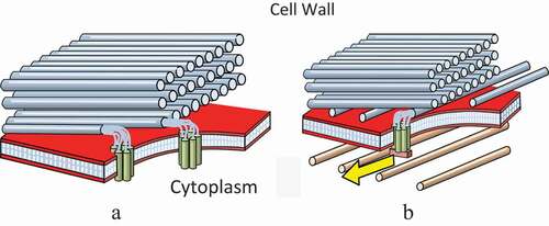
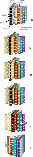
A recent paper by Chan and Coen (March, 2020) proposes a dual mechanism hypothesis for the orientation of cellulose microfibrils in plant cell walls. One of these is an autonomous mechanism, which takes place outside the plasma membrane, within the cell wall itself (a). The other is the more complex microtubule-guided cellulose alignment process, where the orientation of microfibrils is directed by microtubules within the cell, via trans-membrane protein complexes (rosettes) (b). This mechanism can override the autonomous process and, it is argued, can explain how the production of complex detailed multi-layer alignment patterns of secondary walls is orchestrated. This paper concerns the latter process. It pushes the model one stage further back, by proposing a mechanism for the initial alignment of microtubules, in terms of the liquid crystalline state of the cortex. Justification for the hypothesis is given in terms of the in-vitro observations of the liquid crystalline mesophase formed by microtubules, and of the self-ordering properties of liquid crystalline systems in general. As an example, the production of a plant cell wall with a helicoidal array of cellulose microfibrils is pictured in some detail.
GRAPHICAL ABSTRACT
1. Introduction: defining the problem
A recent model for the orientation of microfibrils in the plant cell wall, proposed by Chan and Coen [Citation1] and Lloyd and Chan [Citation2] involves a dual mechanism – an autonomous process which takes place outside the cell membrane and an alternative process where the microfibril orientation is determined by the alignment of microtubules at the inner surface of the membrane. This paper extends their hypothesis by proposing a mechanism for directing the alignment of the microtubules involved.
This paper is in three parts. The first defines the problem of how the architecture of plant secondary cell walls is initially directed. The third part is a hypothesis suggesting what appears to be a plausible answer. The intermediate part is a selected group of observations concerning the relevant properties of liquid crystalline phases which are invoked in support of this hypothesis.
The structure of the cell wall of a higher plant is sketched in [Citation3]. The wall is created from the outside, inwards [Citation4,Citation5]. The first part to be laid down is the primary wall. This is constructed as the cell is elongating and consists in the first place, of a fairly random mesh of microfibrils lying more-or-less equatorially – but there is some degree of realignment as the cell extends. In contrast, the newer, secondary wall is a well-defined structure laid down as strengthening when extension of the cell has ceased. As shown in [Citation6] there are highly ordered layers of parallel microfibrils, usually with some angular offset between one layer and the next. In some cases, there is an alternating pattern of two alignments and in others, (including many hardwoods) a more complex repeating sequence of three.
Figure 1. (Colour online) The structure of typical cell wall of a higher plant. It has two distinct parts. The older, primary wall, which has a fairly random winding of more-or-less equatorially-aligned cellulose microfibrils. The later secondary wall is highly structured, with a sequence of distinct layers of highly parallel microfibrils
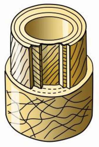
Figure 2. (Colour online) The characteristic appearance of cellulose microfibrils in the secondary wall cell of a higher plant. The microfibrils are about 3–4 nm in diameter. This electron microscope picture shows two well-oriented layers of microfibrils of the secondary wall of Chaetomorpha melagonium viewed from outside the cell. The cell axis runs vertically [Citation5]. Note the accuracy of the long-range alignment, coupled with a level of short-range wandering away from, and then back towards the consensus direction
![Figure 2. (Colour online) The characteristic appearance of cellulose microfibrils in the secondary wall cell of a higher plant. The microfibrils are about 3–4 nm in diameter. This electron microscope picture shows two well-oriented layers of microfibrils of the secondary wall of Chaetomorpha melagonium viewed from outside the cell. The cell axis runs vertically [Citation5]. Note the accuracy of the long-range alignment, coupled with a level of short-range wandering away from, and then back towards the consensus direction](/cms/asset/c14f20f0-9f02-4fed-bd75-6d6a5d4f2eb8/tlct_a_1891476_f0002_b.gif)
Biology textbooks often show pictures similar to , to illustrate the distinction between the primary and secondary walls of plants – and this is perfectly sound. However, it is not always made clear that the figure depicts only a minority of plant cells. In growing herbaceous plants, for example, most cells have no secondary cell wall at all.
The primary wall is laid down by cells that are dividing and growing. The driving force for the expansion during growth, is the turgor pressure (created by the osmotic uptake of water) and, at this stage, the primary walls are thinner and more flexible than those of cells with secondary layers of microfibrils, that have stopped extending.
From a structural viewpoint, a cell with only a primary wall, resembles an inflated balloon held in a string bag – and its rigidity disappears if the pressure is reduced. The role of the primary wall is to prevent the turgor pressure from bursting the cell and to dictate its shape. There is strong evidence that the initial alignment of the microfibrils is the key factor. When the cells are first formed in the meristem, their microfibrils lie in a random mesh. But when they have moved away, and the cell wall begins to thicken with the addition of new interior layers, the older, outer layers become progressively more axially aligned, as shown in .
Figure 3. (Colour online) The development of the primary cell wall as the cell elongates. Each new layer is laid down with a more-or-less equatorial alignment and, as the cell elongates, the alignment becomes progressively more axial as the inter-microfibrilar linkages soften, yield and then re-form. Roelefson termed this process multinet extension [Citation11] but Preston preferred to call it passive growth [Citation6]
![Figure 3. (Colour online) The development of the primary cell wall as the cell elongates. Each new layer is laid down with a more-or-less equatorial alignment and, as the cell elongates, the alignment becomes progressively more axial as the inter-microfibrilar linkages soften, yield and then re-form. Roelefson termed this process multinet extension [Citation11] but Preston preferred to call it passive growth [Citation6]](/cms/asset/5ab13fdf-266a-4159-a669-b20892e5210e/tlct_a_1891476_f0003_oc.jpg)
The secondary wall is laid down after the cell has grown to more-or-less its final length. Its role is to give the cell mechanical strength. This supports the weight of the plant as it grows upwards and it also enables the plant to resist collapse if the turgor pressure falls. In this context, note that plant cells with secondary walls are often dead at maturity with no protoplasmic contents and lack the ability to create turgor pressure.
Electron micrographs of the kind shown in pose a problem. On one hand, it is apparent that well-defined, complex patterns of microfibrils are constant from one plant to another within each species – and the orientation process must therefore be tightly controlled. But on the other hand, there are no obvious overall geometrical features that suggest a common inter-species alignment mechanism extending throughout the higher plants. Nor are there any obvious clues that point towards a straightforward rationalisation. The offset angles between layers are not geometrically significant values of 45°, 60°.or 90° (although they are sometimes close to these values). They range from a few degrees to a right angle. And moreover, although for plants of the same species, corresponding layers of microfibrils have the same orientation with respect to the cell axis, once again they are not at geometrically explicable angles. In structures with alternating, or with three-layer repeating patterns, it is difficult to see any evidence of a general alignment mechanism operating [Citation5].
The cell wall is physically outside the cell. It is isolated from the cytoplasm by the plasma membrane, implying that all materials required for its synthesis, and messages directing its architecture must be channelled through this barrier. Links across the plasma membrane were implied by a crucial discovery in 1974 – where it was noticed that arrays of microtubules in the outer regions of the cortex of the cytoplasm were aligned parallel to the layers of microfibrils on the opposite face of the plasma membrane [Citation6]. This discovery had been delayed for decades, because earlier techniques for preparing samples for electron microscopy had caused microtubules to de-polymerise.
At first there was considerable scepticism about this hypothesis. Transport perpendicularly through the membrane, via a variety of specific channels was becoming a familiar concept to biochemists and botanists – but lateral movement in the plane of the membrane surface was not. It was not generally known how feasible it was to postulate that a sizeable trans-membrane protein complex could link microtubules and microfibrils and be dragged through the membrane parallel to the surface. In addition, for three decades, the fact that there are no centriole-like microtubule-organising centres apparent in the cell cortex was quoted as a reason for questioning the microtubule template model [Citation7] (in spite of the fact that, in plant cells, the machinery of mitosis appears to function successfully without them) [Citation8].
1.1. Primary wall structure
For a brief period (in the1950s and 1960s), attention was focussed on the structures of the cellulose microfibrils in the expectation that this might shed some light on the mechanism of their alignment – and it was found that the biologically-occurring form is not the lowest energy state. The material recovered from a solution in, for example, cuprammonium sulphate, is reconstituted with a different pattern of hydrogen-bonding to that between the native cellulose chains in a cell wall [Citation9]. Microfibrils themselves are highly crystalline and show up very clearly in X-ray diffraction studies but there are significant quantities of other more amorphous components which were not so apparent. The matrix between the microfibrils was found to be a complex mixture of polysaccharides and proteins. The plant cell wall is not simply a suspension of highly crystalline cellulose microfibrils lying in an aqueous mother phase. It soon became clear that the mechanism involved in microfibril orientation must somehow involve the material between the fibrils rather than the molecular structure of the fibrils themselves. In some way, it manages to solve the recurrent problem faced by any living system which has a exoskeleton, and is able to carry out two opposing functions – acting as both a lubricant (allowing microfibrils to realign in the growing cell), and as a glue enabling the wall to resist turgor pressure) [Citation5,Citation10].
Early approaches concerning the architecture of plant cell wall, such as the multinet growth theory of Roelefson and Houwink [Citation11] (later renamed the passive growth theory by Preston [Citation6]) attempted to explain the realignment of cellulose chains which accompanies the extension of the cell. This comes dangerously close to a circular argument, where microfibrils are aligned by asymmetric elongation of the cell and conversely, the asymmetric elongation of the cell is a consequence of the alignment pattern of the microfibrils. The two factors may well be mutually supportive – but a de novo explanation is lacking.
What appears to be the generally accepted picture of microfibril re-alignment during the growth of the primary wall is shown schematically in .
The spherical shape of the unusual single-celled alga shown in would appear to rule out any model involving microfibril alignment caused purely by the asymmetric shape of the cell, in at least this particular case. And, if there if there is a general mechanism for microfibril alignment throughout the plant kingdom, there must be factors of a qualitatively different nature involved.
Figure 4. (Colour online) Stylised drawing of a vesicle of the single-celled marine alga Ventricaria ventricosa (formerly known as Valonia ventricosa) [Citation6]. This alga grows as a sphere up to about 20 mm in diameter. The thick cell wall consists of about 40 layers of cellulose microfibrils in a repeating sequence of three orientations of microfibril layers, as sketched here. They are inclined at angles of approximately (but not precisely) 120° to each other. Redrawn from [Citation6]
![Figure 4. (Colour online) Stylised drawing of a vesicle of the single-celled marine alga Ventricaria ventricosa (formerly known as Valonia ventricosa) [Citation6]. This alga grows as a sphere up to about 20 mm in diameter. The thick cell wall consists of about 40 layers of cellulose microfibrils in a repeating sequence of three orientations of microfibril layers, as sketched here. They are inclined at angles of approximately (but not precisely) 120° to each other. Redrawn from [Citation6]](/cms/asset/8ae395af-1c07-4601-abfb-8e5dc310dfeb/tlct_a_1891476_f0004_oc.jpg)
There is one particular structure which occurs in the secondary wall in a scattering of plant species, which has attracted attention because of its geometrical simplicity – and is discussed below. This is the case where a there is a constant small angular offset which consistently extends across a large number of layers – producing a helicoidal structure. Over the years, this pattern has been seized upon by some workers studying plant cell walls, as being highly significant (– whilst, at the same time, being completely ignored by others proposing alternative theories, and who found it inconvenient).
This paper concerns the orientation of microfibrils as initially laid down in the secondary wall, when the cell growth has largely ceased (and where effects due to elongation of the cell can no longer be a decisive factor). The alignment mechanism postulated below involves the spontaneous formation of a liquid crystalline state in both the outer layer of the cortex of the cytoplasm and the interfibrillar matrix of the existing wall. And it is therefore appropriate to outline the relevant properties of liquid crystalline phases which will be invoked later.
2. The self-ordering properties of liquid crystalline phases
Introductory articles about liquid crystalline phases customarily begin by describing them as being intermediate in molecular ordering between the crystalline solid and the (isotropic) liquid. This statement, whilst being true, is also grossly misleading. It implies that all of the properties will be intermediate – which is far from the case. The combination of structure and fluidity brings with it a number of properties not shared by any other type of phase. For example, the widespread use of liquid crystalline material in display devices stems from the ease with which they can be aligned and realigned by relatively weak electric fields. In contrast, it takes an enormous potential (orders of magnitude greater) to realign a molecule within the phase of either a crystalline solid or an ordinary (isotropic) liquid. Here we are concerned with another such unique property of liquid crystalline materials – that of spontaneous self-aligning.
2.1. Spontaneous alignment of liquid crystalline systems
The liquid crystalline phase has, with considerable justification, been called Nature’s delicate phase of matter [Citation12]. Materials in this state are, in general, sensitive to a wide range of changes of condition – of concentration, temperature, the application of relatively weak electric or magnetic fields, the presence of small amounts of chiral additives, and the boundary conditions at the surfaces. They can position and align solid inclusions [Citation8] and most remarkably, they have the ability to spontaneously align the whole of a sample in response to the shape of the containing vessel and the geometry of the surface alignment, as illustrated in The sum total of all of these factors, makes liquid crystalline phases uniquely versatile as self-ordering systems and (– although you might not find it mentioned in current undergraduate textbooks) biological systems have exploited them to the full.
Figure 5. (Colour online) Examples of alignments spontaneously adopted by nematic liquid crystalline phases when confined in an extended cylindrical container, as determined by the epitaxial interactions at the surface. a) The uniform axial pattern resulting from a ‘planar’ surface alignment. b) The ‘escaped’ radial pattern adopted when the surface alignment is normal. Note that the curvature of the director field varies from zero at the surface to a maximum value at the central axis [Citation8]
![Figure 5. (Colour online) Examples of alignments spontaneously adopted by nematic liquid crystalline phases when confined in an extended cylindrical container, as determined by the epitaxial interactions at the surface. a) The uniform axial pattern resulting from a ‘planar’ surface alignment. b) The ‘escaped’ radial pattern adopted when the surface alignment is normal. Note that the curvature of the director field varies from zero at the surface to a maximum value at the central axis [Citation8]](/cms/asset/fc1dafcd-59c6-4448-a124-a1819c785477/tlct_a_1891476_f0005_oc.jpg)
Dozens of structurally distinct liquid crystalline phases have now been identified – but in this paper we are only concerned with two. These are the nematic phase and its twisted variant, (formed by chiral systems). In older literature, for historical reasons it was termed the cholesteric phase, but now it is conventionally named the twisted nematic. [Note that this should not be confused with the director field pattern in twisted nematic displays, which is created by the orthogonal epitaxial alignment at the two substrate / mesophase interfaces].
The particular nematic phases we are concerned with here are those formed by elongated macromolecular units lying in a parallel array in an aqueous solution or suspension. The origin of the word nematic is interesting (– and relevant to a later section of this paper). It is derived from the Greek word nematos, meaning thread. When the phase was first observed in the 1890s it was noticed that bulk samples appeared to contain fine threads [Citation6,Citation7]. These had the appearance of tangible objects – but any attempt to remove them only created more. Polarising microscopy showed that they were not in fact, solid inclusions, they were actually disclinations, (discontinuities in the alignment pattern) where the molecules had become locked in a shallow local energy minimum). They can remain indefinitely, provided they are not disturbed too much. However, they can be ‘combed out’ by applying electric or magnetic fields or by zone-refining – and can be avoided in liquid crystal displays by using aligning surfaces.
Two examples of the self-ordering properties of liquid crystal phases are shown in . They both depict a sample of nematic liquid crystalline material contained in a cylindrical tube. In (a) there is a uniform axial pattern resulting from a ‘planar’ surface alignment, and (b) shows the ‘escaped’ radial pattern adopted when the surface alignment is normal. The epitaxial alignment of liquid crystal phases is utilised in the majority of commercial liquid crystal displays. It has been extensively studied, and recipes for treatments giving the desired alignment have been accumulated for many commercially-used materials. In at least one well-documented example, a small change of temperature is sufficient to convert planar orientation into perpendicular – a causing drastic changes to the director field (pattern of alignment) of the entire sample [Citation13,Citation14].
Note the spontaneous creation of the axial line of disclination in ). The combination of the fluid state of the material coupled with the non-zero values of the various elastic constants for deformation of the phase (for bend, twist and splay) enables the phase to ‘sense’ the position of the centre line of the container. A purely radial pattern would lead to energetically unacceptable congestion near the centre, with high splay distortion energy. As a consequence, there is a deflection of the director field from radial to axial as the centre line is approached. This feature has been elegantly termed ‘escaping into the third dimension’.
Note that this axial disclination is just a line in space. The entire system is fluid and molecules can drift through it without disturbing the pattern of molecular alignment. Although the sample may be chemically homogeneous, it is not physically uniform. The curvature of the director field, and hence the strain on the sample, varies according to the distance from the wall. Solid inclusions in the system tend to be steered towards positions of lowest energy – as determined by their shape and the nature of their surface interactions with the host phase. For the system shown in 5b, inclusions with a planar surface alignment will accumulate along the centre line. There are other similar patterns of spontaneous microtubule alignment which, I suggest, are similarly involved in biological structure-forming processes. In a previous paper [Citation8], a model was proposed for process of determining the position of cell plate during plant cell mitosis. And it is now suggested here as an explanation of how (and why) microfibril growth (of secondary walls) starts in the equatorial plane and is directed towards the ends of a plant cell.
Liquid crystalline system are the self-ordering phases par excellence – and they would appear to be capable of directing any of the various patterns found in in the wide repertoire of plant cell wall architecture.
2.2. Helicoidal structures
The study of liquid crystals is usually traced back to a chance discovery in 1888 by the Austrian botanist Friedrich Reinitzer, when he was studying derivatives of cholesterol. He was startled by the appearance of a transient iridescent phase formed when he allowed a melt of cholesteryl benzoate (derived from carrots!) to cool [Citation15]. This phase was so intriguing that it demanded attention, and he sent a sample of the material to Otto Lehmann, (Professor of Physics at the University of Paris) for investigation – and the rest is history [Citation16].
The remarkable optical properties of this iridescent phase (i.e. the colour and the selective reflection of circularly polarised light) were found to be the same as those of iridescent insect cuticles, which had been previously studied by Michelson [Citation17] (of Michelson / Morley experiment fame [Citation18] and were identified as being produced by a helicoidal structure as sketched in .
Figure 6. (Colour online) (a) A stylised representation of a helicoidal array of rods, showing the appearance of an obliquely-cut surface. Note the illusion of ‘nested arcs’ (Bouligand patterns) [Citation27] drawn in red. Patterns of this kind have been found in electron micrographs of a wide range of biological structural materials notably the cuticles of iridescent beetles [Citation17–22] – and some plant cell walls [Citation28]. (b) The conventional stylised representation of helicoidal material, (the twisted plywood structure), indicating a single pitch of the structure
![Figure 6. (Colour online) (a) A stylised representation of a helicoidal array of rods, showing the appearance of an obliquely-cut surface. Note the illusion of ‘nested arcs’ (Bouligand patterns) [Citation27] drawn in red. Patterns of this kind have been found in electron micrographs of a wide range of biological structural materials notably the cuticles of iridescent beetles [Citation17–22] – and some plant cell walls [Citation28]. (b) The conventional stylised representation of helicoidal material, (the twisted plywood structure), indicating a single pitch of the structure](/cms/asset/ee42e163-6533-4dd9-8031-c05a2926c2ce/tlct_a_1891476_f0006_oc.jpg)
Since Michelson’s study, iridescent insect cuticle has been intensively studied. By adjusting the pitch at different levels in the structure a collection of selective colours can be reflected simultaneously, and some remarkable effects can be produced. The piece de resistance must surely be the sheen of beautiful metallic gold covering the chrysalids of the South American cream-spotted tigerwing butterfly, Tithoria tarricina.
Helicoidal structures of this kind are common in virtually all biological structural materials – including cellulose, chitin and collagen [Citation19–22]. They also occur spontaneously as liquid crystalline phases, in solutions of nucleic acids, synthetic polypeptides, and polysaccharides [Citation23] and suspensions of virus particles [Citation24,Citation25] – and most significantly with respect to this paper, in in vitro solutions of microtubules [Citation26].
In the classical small-molecule, large-pitch, twisted nematic phase the only order within the structure is orientational and there is no positional regularity in any dimension. The twist angle between adjacent molecules may be a matter of a few seconds of arc, and at close range the structure is more-or-less indistinguishable from that of an untwisted nematic phase. However, for systems with elongated polymeric units, with a short pitch, some degree of layering, perpendicular to the twist axis, becomes inevitable because of packing considerations – as is apparent in
The twisted nematic phase is the only material known which is able to form helicoidal structures spontaneously – and the inference is that all biological materials with this structure are, in some way, dictated by a preceding helicoidal liquid crystalline system. This is not to say that in all cases the processes involved must have been identical – it is merely arguing that somehow, directly or indirectly, the structure has been templated from a twisted nematic phase. The sketch in shows the structure spontaneously adopted by some twisted nematic phases when enclosed in a cylindrical tube.
Figure 7. (Colour online) A stylised representation of the structure spontaneously adopted by twisted nematic phases when enclosed in a cylindrical tube, with planar alignment of molecules at the boundary. The helicoidal structure is indicated in the conventional manner (as shown in ). Well-developed patterns of alignment of this kind have been found in a range of in vitro systems, including suspensions of helical viruses [Citation24,Citation25]
![Figure 7. (Colour online) A stylised representation of the structure spontaneously adopted by twisted nematic phases when enclosed in a cylindrical tube, with planar alignment of molecules at the boundary. The helicoidal structure is indicated in the conventional manner (as shown in Figure 3). Well-developed patterns of alignment of this kind have been found in a range of in vitro systems, including suspensions of helical viruses [Citation24,Citation25]](/cms/asset/ec5521ca-abae-467d-a84c-e1e57e0bbd3f/tlct_a_1891476_f0007_oc.jpg)
The model proposed later, for the creation of helicoidal cell walls, corresponds to the outer shell of this structure.
In , Two specific sites with higher symmetry than the bulk of the phases, are indicated. The green circles mark the cross-section of an annular ring. The brown line marks the plane of disclination separating the two domains. There are similar sites in domain patterns of untwisted nematic phases held in cylindrical tubes – and these have been invoked in explaining the formation of the mitotic spindle and the cell plate [Citation8].
Structures of this kind can form in patterns of closed domains – and the boundary between two of these is shown here. In addition to the central axis, there are positions within this director field pattern which have higher symmetry than the remainder of the phase. They can be sites of local energy minima for inclusions with the appropriate structures and surface properties. In particular, the vertical line, outlined in brown, indicates the boundary plane between the domains and the green circles indicate the position of an annular equatorial ring. Both of these features have been invoked in explaining the geometry of mitosis in plant cells – with the positioning of the cell plate in the first case and of the annular rings formed in both the pre-metaphase and late metaphase stages, in the second [Citation8] .
If their pitches lie outside the visible optical wavelength range, helicoidal materials do not show any visible iridescence and there may not be any obvious indications of the nature of the material. However, electron micrographs of helicoidal material (including those with pitches out of the visible wavelength range) can be recognised from the characteristic appearance of oblique sections. As sketched in , these show images of nested arcs, known as Bouligand patterns [Citation27]. They are very well defined in the microscopy the cuticles of iridescent beetles – and have been observed in the electron micrographs of some plant cell walls also [Citation27].
Before Yves Bouligand’s explanation of this pattern, workers studying insect cuticle and plant cell walls (at least those in Preston’s laboratory at Leeds) had been racking their brains for years trying to think of a plausible mechanism which could produce repeating patterns of nested, curved fibres. When Bouligand’s elegant explanation, first appeared, they were slow to accept it – partly because they had never encountered Michelson’s work and partly because structures with pitches of such dimensions were not familiar concepts to biologists (or X-ray crystallographers, at that time). They were not alone in this. An article by Peter Albersheim in the August edition of the 1975 Scientific American [Citation28] featured an electron micrograph of an oblique section of the cell wall of a ‘marine grass’. This showed an unmistakeable Bouligand pattern of nested arcs, similar to that sketched in . It attracted international attention and some correspondence, since the author had stated that the origin of this pattern was unknown to him. At least six letters were sent to the editor identifying the structure concerned as a characteristic view of an oblique section of a helicoidal structure – but none was published (Personal communication from the editor of Scientific American, at that time. (I wrote one of the six letters and I presume that Yves Bouligand would have written one of the others).).
Although Bouligand patterns of microfibrils have been recognised in plant cell walls since the 1970s, it was surprising that no botanical material had been found with iridescence comparable to that of insect cuticle until 2012 [Citation29]. This belated discovery concerned the shiny fruit of Pollia. A novel explanation was offered for its evolutionary value. The seeds are dispersed by birds and it is important that the fruit should look appetising. However, although the berries have an eye-catching deep purple colour and gleam, making them appear juicy to a hungry bird, they are in fact dried-up husks. Presumably, by the time a bird has swallowed one, it had achieved its purpose. In the same way that insects had presumably acquired iridescence by accident and then acquired the ability to use it for identification or disguise [Citation30], this plant had stumbled upon a potentially beneficial property and had retained and optimised it. [Please excuse the blatant anthropomorphism.]
At first, helicoidal liquid crystalline phases were regarded as rare and complex. However, as more examples were found, they have come to be seen in a different light. Rather than being viewed as exotic, the helicoidal structure has come to be regarded as the natural default state of any soft matter containing a significant concentration of reasonably rigid helical polymers.
The twisted nematic phase is the only known material which is able to form helicoidal structures spontaneously – and the inference is that helicoidal structures found in biological systems have passed through a preceding transient helicoidal liquid crystalline phase. In the case of insect cuticle, the precursor appears to be simply secreted over the surface of the cuticle as a liquid crystalline fluid, and the structure is preserved when the material hardens.
At one stage, in the 1960s, following the identification of helicoidal structures in some plant cell walls, the site of microfibril alignment was presumed to be within the cell wall itself. A similar process was envisaged to that which produces helicoidal ordering in insect cuticle [Citation20,Citation21] and it was considered that the aligning factor must be the matrix between within which the microfibrils were embedded. The idea had some attractive features, bearing in mind that the wall lies outside the plasma membrane. It offered a way in which the cell could control microfibril alignment structure at arm’s length, by extruding material which was self-ordering. However, the chitin cuticle/protein complex of insect cuticle is in no way as highly structured and dynamic as the plant cell wall. A corresponding process would lack the capability for aligning and realigning fibres of virtually infinite length during growth of the cell, without destroying its vital mechanical strength. It was generally accepted that at least some of the features of cell wall architecture would require a far more sophisticated process.
Chan and Coen’s clear formulation of a dual mechanism was long overdue.
Our findings suggest a dual guidance model, in which an autonomous system, involving interaction between cellulose synthases and microfibrils, can maintain aligned cellulose synthase trajectories, while a microtubule guidance system allows alignments to be steered by environmental and developmental cues [Citation1].
This follows a long line of descent from the earlier studies of the effect of the mitotic poison, colchicine, which acts by supressing the production of microtubules by the aggregation of tubulin dimers [Citation30]. It shows that the cellulose synthase trajectories can be maintained in the absence of microtubules and indicates that there must be a separate guidance mechanism.
This does not affect the thrust of this paper (– which is a hypothesis specifically relating to one of the dual mechanisms – the microfibril orientation in the secondary wall by the process of templating from patterns of microtubles in the cortex). It does, however, define its context.
3. The postulated mechanism of microfibril alignment
3.1. Liquid crystalline phases of microtubules
The subgroup of liquid crystal phases of concern here, consists of solutions of biological polymers involved in the cytoskeleton, in particular the liquid crystalline phase formed by microtubules. For most of the cell cycle, the cytoplasm is a reservoir of unpolymerised tubulin dimers. However, on command, these can polymerise giving unbranched linear polymers which, in sufficient concentration, spontaneously producing a liquid crystalline array, whenever required by the cell (as for example during formation of the mitotic spindle) [Citation8]
It would appear that any plausible general mechanism for cell wall architecture must be able to produce a helicoidal arrangement, with a constant angular offset between adjacent microfibril layers (even if other factors can override it). For this reason, the hypothesis proposed below describes the orientation of a helicoidal array of microfibrils.
A major landmark in the long search for the mechanism of microfibril alignment occurred in 1972 when electron microscopy by Robinson et al. showed numbers of large circular objects with diameters of about 40 nm apparently attached to the surface of the plasma membrane [Citation31]. These were identified as the sites of microfibril synthesis and were termed ‘terminal bodies’ since they appeared to be attached to the ends of microfibrils. Later electron microscopy showed them to have internal detail. Each was a hollow cylinder composed of a ring of six subunits and these complexes were subsequently known as a ‘rosettes’ (in spite of the fact that roses only have five (or multiples of 5) petals (as sketched in ).
Figure 8. (Colour online) This stylised sketch depicts the complex structure of a rosette, nested in the lipid bilayer of the plasma membrane. It is shown in the act of producing a cellulose microfibril. Each of the six components is producing six poly-β-D glucose strands – and all 36 of these then ‘crystallise’ by hydrogen bonding to produce a microfibril. The vertical blue arrow indicates the arrival of cellulose precursors from the Golgi
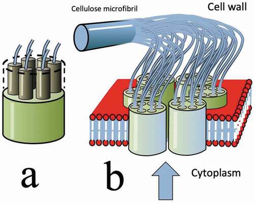
In this, and subsequent stylised sketches (), the component parts (membranes, rosettes, microfibrils, microtubules etc.) have not been drawn to scale – and features not relevant to the synthesis and orientation of microfibrils have been omitted. In particular, no attempt has been made to show the complexity of composition of a real membrane – in terms of its mix of lipid species, or the presence of other transmembrane structures such as the those concerned with the pumping of water and ions into or out of the cell.
Figure 9. (Colour online) Schematic representation of the production of a cellulose microfibril by a rosette
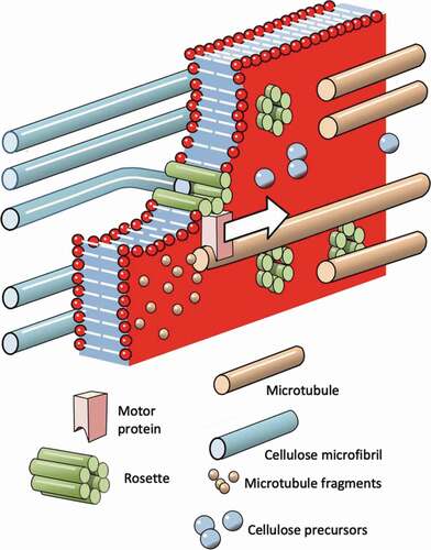
Figure 10. (Colour online) Schematic representation of the way in which a helicoidal pattern of microtubules in the cortex of the cytoplasm directs a corresponding helicoidal pattern of microfibrils in the secondary cell wall. In this figure, the various layers of microtubules and microfibrils have been drawn like pages of an open book. This was to enable the orientations within each layer to be shown. It is intended to show how the sequence of microtubule layers is read, and the corresponding sequence of microfibril layers is created. It is not intended to portray the actual three-dimensional structure of the system at any stage
Microtubules are 23–27 nm in diameter and cellulose microfibrils are about 3 nm in diameter. The lipid bilayer is about 10 nm thick (- allowing for the lyophilic head groups and a few strands of associated polysaccharide.
3.2. The machinery of microfibril orientation
The cellular machinery involved in microfibril alignment of the secondary wall is depicted schematically in . Each rosette is anchored to a microtubule by a motor complex and is drawn laterally through the membrane in a direction parallel to the surface, leaving a microfibril behind – like a vapour trail. As the motor proteins drive the rosettes, the microtubules are dis-assembled behind them (in the same way that the spindle microtubules are dismantled behind chromatids in the later stages of mitosis). And, it is suggested that the layered structure of the cell wall is a consequence of alternating periods of assembly and destruction of the outermost layer of the microtubules.
The stylised shows the way in which a plant cell can lay down a helicoidal plywood pattern of microfibrils in the secondary wall. It is suggested that the cortex of the cell contains a number of helicoidal layers of microtubules and these are ‘read’ in turn, one at a time as depicted. It is argued that a helicoidal shell, with three or four turns of helix, fitting into the highly curved envelope of the plasmalemma would be sufficiently robust to allow the outermost layer to be dismantled without the remainder of the microtubule array being fragmented.
In support of this hypothesis, it is pointed out that there are other biological process involving microtubules on one side of a membrane directing the movement of objects on the other side. For example, in the cell division of yeasts and other primitive organisms which lack a mitotic spindle, where identical halves of the genetic material of the mother cell, are being separated into the daughter cells. The example sketched in , shows the operation of the trans-membrane apparatus that segregates chromatids in the later stages of the ‘closed’ mitosis (where the nuclear membrane remains intact throughout) of some dinoflagellates [Citation32,Citation33].
Figure 11. (Colour online) A stylised diagram of the ‘metaphase stage’ of the ‘closed’ mitosis of some diatoms (where the nuclear membrane remains intact as the chromatids are separated). Note the way in which microtubules (shown in yellow) align in a tunnel through the nucleus and the chromosomes are attached to microtubules via the transmembrane protein complexes (shown in green) and motor proteins (shown in red) [Citation33–35]. Figure redrawn from Mitosis-Wikipedia, en wikipedia.org [Citation31]
![Figure 11. (Colour online) A stylised diagram of the ‘metaphase stage’ of the ‘closed’ mitosis of some diatoms (where the nuclear membrane remains intact as the chromatids are separated). Note the way in which microtubules (shown in yellow) align in a tunnel through the nucleus and the chromosomes are attached to microtubules via the transmembrane protein complexes (shown in green) and motor proteins (shown in red) [Citation33–35]. Figure redrawn from Mitosis-Wikipedia, en wikipedia.org [Citation31]](/cms/asset/051d6b7c-83e4-4c81-b3f0-54771e819e33/tlct_a_1891476_f0011_oc.jpg)
3.3. Production of complex microfibril patterns
Nematic phases of liquid crystalline material are, in general, very sensitive to the addition of chiral dopants and are easily twisted into helicoidally-organised states, and their pitches can be increased or decreased by changing the concentration. Since the vast majority of biological compounds are chiral.it would appear therefore, to be a straightforward matter for the cell to regulate the angle between adjacent microfibril layers by controlling the concentration of chiral solutes present in the cortex (– or alternatively, this could be achieved by changing the effective twisting power of the materials already present, simply by modifying the ionic strength or pH).
Some plants form cell walls with a sufficient number of helicoidal layers of microfibrils to show the characteristic Bouligand pattern of nested arcs. To produce these would require a small angle of twist between adjacent microtubule layers. If however, there is a large twist angle, the removal of each layer after it has been ‘read’ – must cause a significant global reorientation of the remaining multi-layer assembly of microtubules, with respect to the geometry of the whole cell – as it adjusts its orientation within the cell to an accessible minimum energy state. This could explain the presence of strange ‘non-geometrical’ angles. It is suggested that layer-offset angles close to 90° could lead to alternating patterns of alignment and that twist angles close to 60° could lead to the three-layer repeat patterns (found in the cells of hardwood timber).
The sketches in picture the two mechanisms. In the autonomous process (a) new microfibrils take up alignment of the preceding layer. I suggest that the large surface area of the array of parallel fibrils, aligns the matrix material between them – producing a phase with an aligned fluid (i.e. liquid crystalline) state. Chan and Coen mention the trajectories of the previous microfibrils assisting this alignment process [Citation1]. Bearing in mind, that microfibrils are growing through the matrix material, and the property of nematic phases mentioned earlier – to retain a memory of mechanical disturbances in the form of disclination lines – this appears to offer some substance to the concept of a trajectory.
Figure 12. (Colour online) The dual mechanisms of cell wall formation. (a) The autonomous process. This is totally extracellular and takes place outside the plasma membrane. The matrix between the existing microfibrils is aligned in a nematic state, with its director parallel to the existing array of microfibrils – and directs the growth of a new microfibril accordingly. (b) The microtubule alignment process. This is shown overriding the autonomous process and redirecting a new layer of microfibrils
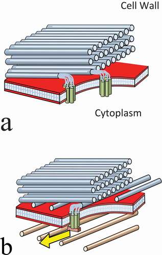
In ) the cortex microtubule alignment process has been switched on. It is overriding the autonomous process and directing the new microfibrils into the alignment of the microtubules. When it is switched off, the autonomous process will take over again, and direct the production of more layers copying the current alignment.
The autonomous mechanism is the default state which can be overridden by the microtubule-guided mechanism when required. Periods of more or less parallel alignment of microfibril deposition can be interrupted by sudden orientation changes when the microtubule alignment is switched on. A simple programme of instructions can be envisaged to account for the observed range of cell wall structures. It would only require three or four parameters to direct the production of alternating patterns – or of the complex three-layer repeating pattern of the cells of hardwood timber :-
An on/off switch for microtubule override.
information giving the orientation of the microfibril layer about to be formed.
The complexity of plant cell wall structure is beginning to look comprehensible.
No doubt it is unwise to predict that the Chan and Coen model is the last major piece in the jigsaw – but it appears to point, at last, towards the big unified picture – a scheme which encompasses all patterns of cell wall architecture. And as one might expect, it gives a hint of the evolutionary game-changing event which took place when the appearance of an alternative mechanism for aligning microfibrils led to the development of load-bearing cell walls – allowing the growth of tall plants, and changing the appearance of the land surface of the Earth for ever.
To return to the quote from Lloyd and Chan given as a preface, to this paper – microtubules involved in plant cell wall synthesis do not require a centriole-like structure to organise them. Their liquid crystalline arrays are sensitive and versatile. Like those involved in plant mitosis, they can be adequately organised in other ways [Citation8]. The hypothesis proposed for the liquid crystalline state of the cortex of the plant cell is capable of directing the component features in the sequence of operations involved in laying down the secondary wall, and when combined with the autonomous alignment process can, in principle, account for the production of complex repeating patterns of microfibrils in plant cell walls
An earlier version of this hypothesis was described in outline in an invited lecture to the joint meeting of the British and German Liquid Crystal Societies in Manchester in 2015 and published in Molecular Crystals and Liquid Crystals 2017 [Citation36]. It did not include the dual mechanism hypothesis or the suggestion made here, that the ‘one layer at a time’ pattern of microfibril deposition involves the progressive destruction of each layer of microtubules as the rosettes are hauled to the end of their journeys.
Acknowledgments
I acknowledge with gratitude, help and advice from my colleagues at The University of Leeds - Professor Paul Knox, without whom I would not have been able to write this paper, for his considerable help concerning the present state of understanding of plant cell wall synthesis, and from Professor Eric Blair, Dr David Pilbeam and Professor Richard Bushby for their assistance and advice on this paper.
I would like to dedicate this paper to Professor R. D. Preston FRS, pioneer of plant cell wall studies – who magnanimously gave me a job, but (quite justifiably) never accepted a word I said, at that time, about the biological roles of liquid crystals.
I am grateful to the Faculty of Biological Sciences, The University of Leeds for appointing me a visiting fellow.
Disclosure statement
No potential conflict of interest was reported by the author.
References
- Chan J, Coen E. Interaction between autonomous and microtubule guidance systems controls cellulose synthase trajectories. Curr Biol. 2020;30:941–947.
- Lloyd C, Chan J. Microtubules and the shape of plants to come. Nat Rev Mol Biol. 2004;5:13–22.
- Picture redrawn from Plomion C. Grégoire Leprovost G. Stokes. Wood formation in trees. 2001. Available from: www.Plantphysiology,plantphysiol.org
- Albersheim P, Darvill A, Roberts K, et al. Plant cell walls. New York: Garland Science, Taylor & Francis; 2010. ISBN-10:0815319967; ISBN-13: 780815319962.
- Cosgrove DJ. Growth of the plant cell wall. Nat Rev Mol Cell Biol. 2005;6(11):850–886. This article is linked to a research highlight by Lyza Maron.
- Preston RD. The physical biology of plant cell walls. London: Chapman and Hall. Springer Science Business Media New York eBook; 1974. ISBN 978-1-5041-2217-7.
- Heath IB. A unified hypothesis for the role of membrane bound enzyme complexes and microtubules in plant cell wall synthesis. J Theor Biol. 1974;48:445–449. PMID: 4459594.
- Lydon JE. A liquid crystal model for cell division - and the enigma of centriole involvement in mitosis in animals but not plants. Liq Cryst Today. 2020;28(4):86–95.
- Gardner KH, Blackwell J. The structure of native cellulose. Biopolymers. 1974;13:1975–2001.
- Zhang HT, Tang H, Vavylonis D, et al. Loosening from softening: insights into primary cell wall structure. Plant J. 2019;100(6):1100–11178.
- Roelofsen PA, Houwink. AL. Architecture and growth of the primary cell wall in some plant hairs and in the phycomyces sporangiophore. Acta Bot Neerl. 1953;2:218–225.
- Collings PJ. Liquid crystals: nature’s delicate phase of matter. 2nd ed. Bristol: Adam Hilger; 1990. ISBN 0‐7503‐0055‐8.
- Lavrentovitch OD, Kleman M. Defects and topology of cholesteric liquid crystals. ScienceDirect; 2018 Oct 1.
- Lavrentovich O. Topological defects in dispersed liquid crystals, or words and worlds around liquid crystal drops. Cambridge: University Press; 2000. (Downloadable).
- Reinitzer F. Monatsh. Wiener Chem Gesell. 1888;9: 421. and see Lehmann O. 1911 Die Flussige Kristalle, Akademische Verlags-gesellshaft M.B.H., Liebzig.
- Dunmur D, Slukin TA. Soap, science, and flat-screen TVs: a history of liquid crystals. Oxford (UK): Oxford University Press; 2010. p. 17–20. ISBN 978-0-19-954940-5.
- Michelson A. On metallic colouring in birds and insects. Philos Mag. 1911;21(554–567):14.
- Michelson A, Morley EW. On the relative motion of the Earth and the luminiferous ether. Am J Sci. 1887;34(203):333–345.
- Vikusic P, Sambles JR. Photonic structures in biology. Nat Rev Art. 2004;424:852–855. Erratum 2004 Nature 429 (6992) 680-680, 429 689.
- Neville AC, Caveney S. Scarabeid beetle exocuticle as an optical analogue of cholesteric liquid crystalsl. Bio Rev. 1969;44:531–562.
- Neville AC. Biology of fibrous composites: development beyond the cell membrane. Cambridge (England); New York: Cambridge University Press; 1993. ISBN 0 521 410517.
- Wilts B-D, Whitney HM, Glover BJ, et al. Natural helicoidal structures: morphology, self-assembly and optical properties. Mater Today: Proc. 2018; 1S:177–185. 2014. Also --- Wilts, B. D. Sheng, X. Stanislav N. Gorb, E Gorb V - - Science.
- Robinson C. Cholesteric phase in polypeptide solutions and biological structures. Mol Cryst. 1966;1(4):467–494.
- Bernal JD, Fankuchen I. X ray and crystallographic studies of plant virus preparations (part 1). J Gene Physiol. 1941 20;25(1):147–165. PMCID:PMC2142030 PMID:19873255.
- Dogic Z, Fraden S. Ordered phases of filamentous viruses. Curr Opin Colloid Interface Sci. 2006;11:47–55.
- Hitt AL, Cross AR, Williams RC. Microtubule solutions display nematic liquid crystalline structure. J Biol Chem. 1989;265:1639–1647.
- Bouligand Y. Sur une disposition fibrillaire torsadée commune à plusieurs structures biologiques. CR Acad Sci Paris. 1965;261:4864–4867.
- Albersheim P. The walls of growing plant cells. Sci Am. 1975 Apr;232(4):80–95.
- Vignolini S, Rudall PJ, Rowland AV, et al. Pointillist structural colour in Pollia fruit. PNAS. 2012;109(39):15712–15715.
- Warrant EJ. Polarisation vision. Curr Biol. 2010;20(14). DOI:https://doi.org/10.1016/j.cub.2010.05.036
- Robinson DG, White RK, Preston RD. Fine structure of swarmers of Cladophora and Chaetomorpha III. Wall synthesis and development. Planta. 1972;141:83–92. 107 131–144.
- Campbell NA, Reece JB. Biology. 8th ed. Berkeley (CA): Pearson; 2008.
- Raikov IB. The diversity of forms of mitosis in protozoa: a comparative review. Eur J Protistol. 1994;30(3):253–269.
- Desalle R, Schierwater B, editors. Key transitions in animal evolution. Boca Raton (FL): CRC Press; 2011. Available from: https://doi.org/https://doi.org/10.1201/b10425
- Sazer S, Lynch M, Needleman D. Deciphering the evolutionary history of open and closed mitosis. Curr Biol. 2014;24(22):2613–2748.
- Lydon JE. Nature’s universal mesogens. Mol Cryst Liq Cryst. 2016;632(1):29–48.