
 ?Mathematical formulae have been encoded as MathML and are displayed in this HTML version using MathJax in order to improve their display. Uncheck the box to turn MathJax off. This feature requires Javascript. Click on a formula to zoom.
ABSTRACT
Responsive functional composite fibre mats that are mechanically stable and impervious to water exposure are produced by coaxial electrospinning of thermotropic liquid crystal (LC) core inside a water-based solution of poly(vinyl alcohol) (PVA) and poly(acrylic acid) (PAA) forming the sheath. Because thermotropic LCs usually cannot be spun inside water-based solutions due to excessive interfacial tension , a n enabling step is the addition of ethanol or dioxane to the LC as a co-solvent compatible with both core and sheath fluids. This reduces
sufficiently that coaxial jet spinning is possible. After spinning, thermal cross-linking of the PVA+PAA sheath yields LC-functionalised fibres that can be manipulated by hand and remain intact even upon full immersion in water. The LC core retains its behaviour, nematics showing well-aligned birefringence and transitioning to isotropic upon heating above the clearing point, and cholesterics showing selective reflection which is even enhanced upon water immersion due to the removal of sheath scattering. Our results pave the way to producing LC-functionalised responsive fibre mats using durable polymer sheaths, thereby enabling numerous innovative applications in wearable technology, and they also open new opportunities to study LCs in confinement, without visible impact of the container walls.
Graphical abstract
1. Introduction
Non-woven mats of thin composite fibres produced by electrospinning, in which a polymeric sheath confines and protects one or several cores of liquid crystal (LC), have the potential to be of significant practical value [Citation1–3], as they can bring the strongly responsive behaviour of LCs into contexts where they were previously inaccessible. Offering flexibility, breathability and extreme light weight, and combining a textile form factor, high surface-to-volume ratio, and the liquid fluidity yet anisotropic functionality of the LC, these mats could be particularly suitable for clothing-integrated sensors of, e.g. temperature [Citation4–6], strain [Citation4], light [Citation7,Citation8] or volatile organic compound exposure [Citation2,Citation9–11], or for textiles with enhanced mechanical properties [Citation12,Citation13].
Two approaches have been followed for electrospinning fibres with LC cores. Single-phase spinning can be used, in which polymer and LC are co-dissolved in a common solvent and a coaxial core–sheath structure arises as a result of in situ phase separation as the solvent evaporates in flight [Citation9,Citation14–16]. Alternatively, the LC and polymer solution are separated from the start, the LC being introduced as one or multiple cores within the flowing polymer solution using a spinneret with nested channels, in a coaxial geometry for the most common case that only one core is targeted [Citation2,Citation4,Citation17]. Several interesting proofs of concept have been demonstrated using both methods, but the transition from experiments in the research lab to production of functional mats that can be conveniently applied in wearable technology has been slow. Two major obstacles – in many ways related – are of particular importance.
First, the range of polymers used for the sheath has been very limited, most successful experiments being performed with polyvinylpyrrolidone (PVP) [Citation2,Citation4,Citation6–8,Citation10,Citation11]. A sheath of PVP is inappropriate for many applications due to its poor mechanical stability, lack of convenient crosslinking means, and strong sensitivity to humidity. The sensitivity to humidity is very much present also at the stage of spinning in case of the popular choice to use -n-pentylbiphenyl-4-carbonitrile (5CB) as core LC and ethanol-dissolved PVP as sheath: water condensing from the air onto the Taylor cone raises the temperature range of a large miscibility gap between two different isotropic phases in the 5CB-ethanol phase diagram to ambient temperatures [Citation18], triggering uncontrolled multi-interface phase separation that disrupts spinning [Citation19].
The low number of polymers explored for the sheath is a direct consequence of the second obstacle, namely that many textile grade polymers are so chemically similar to the LC that the solvents needed to dissolve the polymer also dissolve the LC very well, and after the solvent evaporates, the LC mixes with the polymer as a plasticiser. Whether using single-phase or multi-channel spinnerets, this tends to lead to fibres that have a uniform cross-section rather than the desired core–sheath structure. The problem can also be the opposite, as in the case of water-soluble polymers like poly(vinyl alcohol) (PVA), yielding an excessively high interfacial tension to the LC that prevents spinning. Surfactants cannot be added to reduce the interfacial tension, because they may mix with the LC core, potentially even bringing in micellized water, either process with severe consequences for the LC behaviour [Citation6].
In this paper, we present an exit strategy from these long-standing obstacles, replacing 5CB with LC mixtures that do not exhibit isotropic–isotropic phase separation in ethanol–water mixtures, using PVA as well as poly(acrylic acid) (PAA) as polymer (), and dissolving them in a mixture of water and ethanol. Additionally, either ethanol or dioxane is added to the LC core, yielding a core–sheath interfacial tension sufficiently low to retain the core-sheath geometry defined by our dual-channel spinneret. As PVA and PAA can be crosslinked together after spinning [Citation20,Citation21], the final fibre mats have sufficient mechanical durability to allow manipulation by hand and they can even be immersed into water without dissolving or the LC leaking out.
Figure 1. The chemical structures of poly(acrylic acid) (PAA), top left, and poly(vinyl alcohol) (PVA), bottom left, and the esterification reaction used to crosslink the two with each other (right).
2. Materials and methods
2.1. Polymer solutions and liquid crystals
Poly(acrylic acid) (PAA; , a polymer soluble in both water and ethanol, was purchased from Sigma-Aldrich and dissolved in anhydrous ethanol (purchased from VWR). Poly(vinyl alcohol) (PVA,
, 85–87% hydrolysed, Sigma Aldrich), highly soluble in water but sparingly soluble (at low concentrations) in ethanol, was dissolved in ultrapure deionised water (conductivity 0.055
, Sartorius Arium). To achieve maximum crosslinking, a PVA-PAA solution containing equal number of carboxylate and hydroxyl groups was prepared from two separate stock solutions of PAA in anhydrous ethanol and PVA in water. The two stock solutions were then mixed together to form a solution with 10% w/w of polymer (PVA+PAA) (see the SI for detailed information).
For the core materials, we used the nematic liquid crystal mixture RO-TN 651 (F. Hoffman-La Roche, Basel, Switzerland), both pure and mixed with 25% w/w CB15 ((S)-4-cyano--(2-methylbutyl)biphenyl, 98%, Synthon GmbH), a chiral dopant added to produce a red-reflecting LC mixture (
nm). In order to facilitate the spinning process, we added either anhydrous ethanol or 1,4-dioxane (
%, Sigma Aldrich) to the core. All materials were used as received without further purification.
2.2. Electrospinning parameters
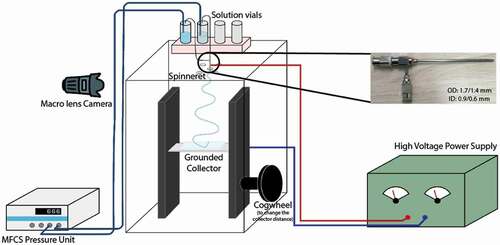
The stainless steel coaxial spinneret (inner diameter: 0.9/0.6 mm; outer diameter: 1.7/1.4 mm) used for electrospinning was purchased from Y-Flow. The outer needle of the spinneret has dents to hold the inner needle in the centre. While not in use, the spinneret was stored in ethanol, and prior to each experiment, the spinneret was carefully cleaned with rinses of 96% w/w ethanol to remove any residues and then thoroughly dried using compressed air at room temperature. The electrospinning setup consisted of a mobile collector wrapped in aluminium foil, placed inside an acrylic box. The spinneret, connected to a microfluidic pressure unit (Fluigent, model MFCS-EZ, maximum pressure 1034 mbar, uncertainty 0.3 mbar) and a high voltage power supply (Gamma High Voltage, model ES30R-5 W/DAM/RS232), was inserted from the top of the box. The Taylor cone (the electrostatically deformed pendant drop from which the fibre-forming jet is ejected in electrospinning) was imaged using a macro lens (Tokina AT-X Pro) mounted on a camera (Pixelink D755). shows a schematic representation of the electrospinning setup.
Figure 2. (Colour online) Schematic representation of the electrospinning setup. The MFCS is the pressure control unit that controls the liquid flow. Inset: The spinneret used for the experiments.
The electrospinning conditions for nematic and cholesteric core are summarised in Table S2 and S3, respectively. Fibres were collected freely hanging on a copper wire frame and on hydrophobized glass microscopy slides to avoid wetting and collapse of the filled fibres [Citation6,Citation22]. These slides were prepared by cleaning 25 mm 75 mm borosilicate glass microscopy slides (Carl Roth) with alternating rinses of isopropanol and deionised water before surface activation with a handheld corona generator for at least 30 s. The plasma-treated slides were then immediately immersed in an aqueous solution of 2% v/v N,N-dimethyl-[N-octadecyl-3-aminopropyl]trimethoxysilyl chloride (DMOAP, 42% in methanol, Sigma Aldrich) and allowed to stand for at least 15 min, with gentle shaking halfway through the soaking procedure to ensure that the solution adequately coated and functionalised the glass slides. The slides were then removed from the treatment solution, rinsed several times with deionised water, and dried under vacuum at 120°C for at least 30 min.
2.3. Optical characterisation
Once collected, the fibres were optically characterised using a polarising microscope (Olympus BX-51) with camera (Olympus DP73) and by scanning electron microscope (SEM). POM characterisation was carried out in transmission mode with the addition of a Linkam heating/cooling stage (T95 series LTS120E, Surrey, UK) to control the temperature of the sample during imaging. SEM imaging of the fibres was performed using a JEOL JSM-6010LA (Akishima, Japan) scanning electron microscope operated at 20 kV with working distance of 11 mm. The fibres were coated with gold ( 5 nm thickness) using a sputter coater (Quorum Q150R ES) for 100 s prior to SEM observation.
2.4. Crosslinking of fibres
After electrospinning, the unfilled and filled fibres were thermally crosslinked through heat-induced esterification by heating under ambient pressure at 130°C for 30 min in an oven (Thermo Scientific Vacutherm). Crosslinking was verified by immersing a fibre mat sample in water; crosslinking was deemed successful when the fibres failed to dissolve after 24 hours immersion.
3. Results and discussion
3.1. Optimisation of the sheath solution
Inspired by the success of Truong et al. in electrospinning mixed PVA–PAA single-phase fibres that could be crosslinked after production [Citation21] by means of an esterification reaction between the two polymers (), we base our sheath solution on this mixture. In this first study, for simplicity, we add PVA and PAA at equimolar carboxyl and hydroxyl group ratio, requiring a slightly higher mole fraction of PVA since it is not fully hydrolysed (see calculation in Supplemental Online Material). An advantage of using PAA as the crosslinking partner to PVA is that PAA – in contrast to PVA – can be dissolved very well in ethanol. This allows us to use a mixture of water and ethanol as sheath solvent, of great benefit to the coaxial electrospinning experiments, as the interfacial tension to the core is lower than with a purely aqueous sheath solution. Preliminary experiments show that 7% w/w of polymer (1:1 mass ratio of PVA and PAA) can be well dissolved in a solvent consisting of 25% w/w ethanol and 75% w/w water, see Supplemental Figure S1.
Before initiating experiments with LC core we spin single-phase fibres from the ethanol–water solution of PVA and PVA and test the effect of crosslinking. We increase the overall polymer content to 10% w/w for the sheath solution to be used for the coaxial spinning. Well-formed fibre mats can easily be spun from the solution and crosslinking by thermal treatment renders them insoluble in water: as shown in Supplemental Figure S2, an uncrosslinked fibre mat dissolves completely within 24 hours when water is poured onto it, while the crosslinked fibre mat, electrospun with identical parameters, shows no sign of dissolution.
3.2. Coaxial electrospinning of composite fibres with nematic core
While the presence of ethanol in the sheath solution significantly reduces the interfacial tension to the LC core compared to the case when pure water is used as sheath solvent,
still appears to be too high if a pure LC core is used, as evidenced by incomplete fibre filling or difficulties to get the LC injected into the jet leaving the Taylor cone, from which the fibres are formed. We therefore add ethanol also to the nematic LC mixture and use the resulting mixture as core. The presence of ethanol in both core and sheath fluids allows fibres that are continuously filled with nematic core to be spun, as shown in ; hence,
has apparently been reduced to an acceptable range.
Figure 3. (Colour online) Taylor cone (a-e) and micrographs of the uncrosslinked (f & g) and crosslinked (h & i) PVA-PAA fibres filled with the nematic LC RO-TN 651, observed with transmission polarising optical microscopy between and without crossed polarisers (crossed double-headed arrows). Scale bars 20 µm. Corresponding movie of the Taylor cone attached as Supplemental Movie 1.
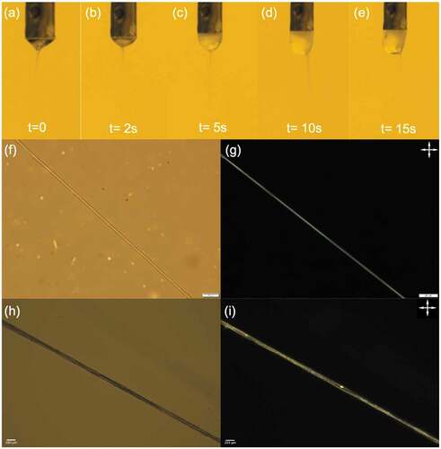
The maximum concentration of ethanol to be added to the core is empirically found to be 30% w/w: a higher ethanol content leads to dilution of the sheath fluid once the two fluids come into contact in the Taylor cone, reducing its stability and even leading to electrospraying rather than spinning. This suggests that the polymer solution becomes insufficiently entangled to prevent the Plateau–Rayleigh instability from breaking up the jet when such a core is used. We attribute this to the reduction of solvent quality for the PVA as the ethanol content in the sheath becomes too high, leading to chain collapse, as well as to the overall reduction of polymer concentration when ethanol flows from core to sheath. This may be further amplified by the ability of a Taylor cone with a high amount of ethanol to condense water from the air, due to the cooling as ethanol evaporates [Citation19]. To avoid these problems while minimising , we add 30% w/w ethanol to the LC unless stated otherwise.
When electrospinning challenging fluid combinations like these, it is imperative to carefully monitor the evolution of the Taylor cone from which the fibres are ejected during spinning. We show representative photos from a successful spinning experiment in ). We start by pumping only the sheath solution and applying the voltage, until a symmetrical and stable Taylor cone has been established. As the core is introduced, we see in ) that the Taylor cone exhibits an overall rather turbid character, rendering the coaxial flow somewhat difficult to see. The core is naturally turbid since it is a bulk nematic phase without uniform orientation of its director field, and the reason for the sheath also becoming turbid is most likely an effect of ethanol diffusing from the core to the sheath. An increase in ethanol content significantly beyond the chosen 25% w/w makes the solvent increasingly poor for PVA, such that it approaches phase separation and becomes turbid. Nevertheless, the spinning situation is stable and the core flow extends all the way from the spinneret to the cone apex, where it injects into the jet to produce coaxial fibres well filled with LC. This is confirmed by studying the as-produced fibres in POM, see ). The fibre is uniformly birefringent ()) with the LC director along the fibre axis. Supplemental Movie 2 shows that the fibre shows good extinction every time the fibre is oriented along either of the polarisers, confirming the excellent uniaxial LC alignment. If the LC flow rate is too high, the Taylor cone is overfilled with LC, growing it into a spherocylindrical shape in which the strong turbidity of the LC is clearly distinguishable from that of the sheath solution, as seen in ). The overfilling also affects the jet ejection, which is shifted to an off-centre location in , most likely because of the reduction in voltage from the charged spinneret to the bottom of the pendant drop. The situation can be stabilised, however, by reducing the core flow rate until the Taylor cone regains appropriate size and the jet returns to its natural position at the cone apex.
After spinning and final solvent evaporation, the PVA and PAA in the fibre sheath are crosslinked using the protocol defined in section 2.4, and then the fibres are again investigated by POM, see ). The LC remains intact in the fibre as confirmed by the birefringence still being present, see ). Supplemental Movie 4 shows that the fibres are still brighter at 45° angle to the polarisers than when they are aligned with the polarisers, but clearly some loss of director alignment has resulted from the crosslinking. To confirm that the birefringence is indeed due to the LC and not due to crystallised sections of the PVA and/or PAA, we heat the fibre above the clearing temperature of the RO-TN 651 LC mixture, where it transitions into an isotropic liquid phase, see . Indeed, the fibres become almost perfectly black at temperatures greater than
()), demonstrating that the original birefringence is solely due to the LC core, which is isotropic and thus not birefringent at high temperature. Importantly, upon cooling back below
, the birefringence recovers and the texture is similar to the original one ()), demonstrating that the LC order recovers as it was prior to taking the core through the phase transition. In these high-magnification images, it is clear that the local texture has changed somewhat as a result of the high-temperature treatment. It appears more compartmentalised, suggesting that the crosslinking of the sheath has partially led to interruptions in the originally continuous core channel. Since many applications of LC-functionalised fibres will use cholesteric rather than nematic liquid crystals, this loss of nematic alignment is not critical, and we will see in the following that the selective reflection of an encapsulated cholesteric core is intact also after crosslinking.
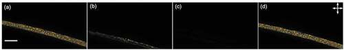
Figure 4. (Colour online) Nematic LC-filled crosslinked PVA-PAA fibres heated above the clearing point () and cooled below it. (a) Before heating; (b) LC clearing as we approach
; (c) the LC appearing dark upon reaching the
; and (d) the colours reappearing on cooling the fibres. Scale bar 20 µm. Images are extracted from Supplemental Movie 3.
3.2.1. Coaxial electrospinning of composite fibres with cholesteric core
The addition of 25% w/w of the chiral dopant CB15 to RO-TN 651 to obtain a red-reflecting cholesteric LC mixture significantly reduces , since CB15 is isotropic at room temperature. Adding ethanol to this mixture led to poor results when attempting coaxial spinning, possibly due to the similarity of CB15 to 5CB, yielding a problematic isotropic–isotropic phase separation in mixtures with ethanol and water [Citation18,Citation19]. For this reason, we searched for an alternative solvent to be added to the cholesteric core which fulfils the need to reduce the effective interfacial tension during spinning, but without inducing phase separation between two isotropic phases. We found 1,4-dioxane to be such a solvent and thus prepared the core fluid by mixing 10% w/w of 1,4-dioxane to the cholesteric LC. When the core fluid comes into contact with the primarily water-based sheath fluid, the dioxane very rapidly mixes with the water in the sheath, while the opposite flow is negligible due to the immiscibility between the LC and water. This dynamic situation produces an extended composition gradient that results in an effective interface with low enough
to allow stable coaxial spinning with the cholesteric LC core and the PVA–PAA solution sheath, see .
Figure 5. (Colour online) Taylor cone at (a) 0 s, (b) 3 s, (c) 10 s, (d) 15 s, and (e) 18 s and micrographs of the uncrosslinked (f & g) and crosslinked (h & i) PVA-PAA fibres filled with cholesteric LC, observed in reflection mode with polarising optical microscopy between and without crossed polarisers. Scale bars 20 µm. Corresponding Taylor cone movie attached as Supplemental Movie 5.
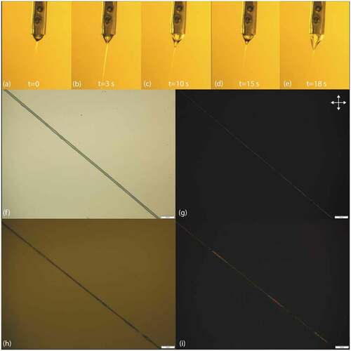
Observation of the Taylor cone during the spinning process () reveals that it changes shape over time, adopting a slightly distorted shape that indicates that some gelation is taking place at the Taylor cone surface. This may be because dioxane is a good solvent neither for PVA nor PAA; hence, the sheath solution gels as the ethanol component evaporates and dioxane takes its place, and composite fibres with continuous cholesteric LC core are obtained, as shown in ). The obtained fibres are rather thin (diameters 1–5 µm) and therefore the selective reflection of the cholesteric core is not observable by the unaided eye. However, using reflection-mode POM confirms the presence of the cholesteric LC in the fibres and the resulting red reflection. As expected for the circularly polarised selective reflection from cholesteric LCs, the colour is constantly visible as the fibre is rotated on the POM stage, irrespective of orientation with respect to the linear polarisers, see Supplemental Movie 6.
As for the nematic core fibres, the mats are crosslinked after all solvent has evaporated, using the same protocol as before, and the fibres are again observed with reflection-mode POM to ascertain the remaining presence of cholesteric LC, see ). There is again some loss of core continuity, but it is not very strong. Most significantly, the red reflection colour is still readily observable. To obtain fibres that do not require microscopy to detect the reflection colour, further optimisation of sheath and core fluid compositions is required in order to allow a greater core flow rate. This will allow the fibre diameter to be increased beyond 5 µm, which is thick enough to allow the reflection colour to be seen by the naked eye, despite scattering from the sheath [Citation4]. However, since the fibres are crosslinked and thus survive immersion in liquids that swell the sheath, we can remove the scattering from the sheath in other ways, as described below.
3.3. Confirmation of resistance to water and test of mechanical durability after crosslinking of the sheath
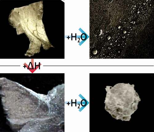
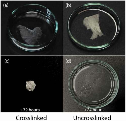
PAA and PVA, being water-soluble polymers, are not particularly suited on their own for making fibre mats that should be used in practical applications. With the two polymers crosslinked to each other in the sheath, however, they become very useful. In particular, crosslinking prevents dissolution, but the hygroscopic nature of both PVA and PAA still allows them to swell significantly in water. To test this, we immerse fibre mats with nematic as well as with cholesteric cores in water and study their behaviour, see for an example with nematic core. As for the preliminary experiments without LC core, the crosslinked samples do not dissolve in water even after immersion for 72 h. The uncrosslinked samples, in contrast, start to dissolve in water within a matter of minutes. After 24 h, the uncrosslinked sample has completely dissolved in water.
Figure 6. (Colour online) Macroscopic samples of mats spun from hybrid PVA/PAA fibres filled with RO-TN 651, both crosslinked (left: a & c) and not crosslinked (right: b & d), viewed without polarisers. While the fibre sample (c) at 72 h after immersion contracted without a supporting frame, it remained intact, especially compared to the fibres without crosslinks in (d) which simply dissolved within 24 h.
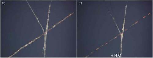
It is particularly interesting to study the cholesteric LC-filled fibres during immersion. Since the PVA-PAA sheath can become highly swollen by water, its refractive index should become much closer to that of the water surrounding the fibres, meaning that the light scattering at the interface between sheath and surrounding water should largely disappear. We confirm this by observing a fibre mat in a Petri dish using reflection-mode POM, as the dish is filled with water, see . Immediately upon immersion, the sheath indeed becomes practically invisible, and the fibres show only the strong red colour due to selective reflection from the cholesteric core ()). The fibres remain fully intact upon water immersion, which further verifies the success of the crosslinking procedure.
Figure 7. (Colour online) Cholesteric LC-filled fibres before (a) and during (b) water immersion, as they appear in reflection POM. The red colour of the cholesteric LC core becomes much more prominent during water immersion, as the scattering from the sheath disappears (b). The fibre running largely vertical in the photo, as well as its diagonal branch, are at slightly higher level and are thus not immersed in water, explaining their remaining scattering. Corresponding movie attached as Supplemental Movie 7.
Finally, we characterise the fibres (both uncrosslinked and crosslinked) at the nanoscopic scale using scanning electron microscopy (SEM), to assess their original surface morphology and how this may change by crosslinking, see . Additionally, a sample of crosslinked fibres that has been immersed in water is dried, and then observed in the SEM to test for any degradation from the water immersion. These investigations show fibres that appear thicker after crosslinking than before ()), which is surprising considering that crosslinking of polymers typically leads to shrinkage. We conjecture that this is due to a certain degree of aggregation of fibres upon crosslinking. Comparing the crosslinked fibres before and after immersion in water, we see surprisingly little change at the individual fibre level in these samples. However, the overall fibre mat was suspended on a frame during this experiment to prevent collapse upon drying due to the capillary forces acting on the fibres as the water evaporates. As shown in ), the capillary forces leads to crumpling together into a dense lump if the fibre mat is not suspended during drying.
Figure 8. (Colour online) SEM micrographs of filled PVA-PAA composite fibres that were (a) uncrosslinked; (b) crosslinked; and (c) crosslinked and dried after immersion in water. Scale bar 50 µm.
We also attempted basic mechanical experiments on the crosslinked fibre mats to test for elongation at break and the maximum tensile stress. Unfortunately, the fibre mats are of a shape that is incompatible with standard mechanical testers and the results were not conclusive. Our general observations are that the fibre mats are significantly more robust than uncrosslinked fibres, such that they can easily be handled with fingers, even with moist skin, in contrast to uncrosslinked fibres of hygroscopic polymers like PAA, PVA or PVP. The degree of crosslinking is high in these fibres with equimolar carboxyl and hydroxyl group content, rendering them rather stiff and brittle. More elastic fibres should be obtainable by changing the PVA:PAA ratio, in turn changing the crosslinking density, and possibly by adding short flexible crosslinker chains, such as hydroxyl-terminated oligoethylenes.
4. Conclusions and outlook
To overcome the long-standing obstacles to making liquid crystal-functionalised electrospun fibre mats that are durable enough for use in wearable technology, we combine PAA and PVA in the sheath such that they can be crosslinked after spinning, resulting in fibres that can be easily manipulated by hand and even fully immersed in water without dissolving and without losing their functional LC core. Since the PVA requires water to be used as sheath solvent, the interfacial tension with the LC core needs to be reduced in order to avoid core break-up due to the Plateau–Rayleigh instability. We achieve this by mixing water and ethanol as sheath solvent and adding either ethanol or dioxane also to the LC core. With ethanol as co-solvent, the two fluids share a common constituent from the start, reducing the interfacial tension. When ethanol is not suitable for the core, dioxane can instead be used, its rapid diffusion into the aqueous sheath phase having a similar beneficial effect on reducing the interfacial tension. While the degree of crosslinking in the sheath of the fibres presented here is higher than optimum, leading to fibres that are rather brittle in their dry state, the same principle can be used to achieve fibres with 10–20% crosslinking in the sheath. With such a modification, we may expect LC-functionalised fibres that are insoluble and mechanically durable, while also being highly flexible and even stretchable, truly opening the path to wearable technology based on electrospun fibres with liquid crystal core.
An interesting side effect of the possibility to immerse the LC-functionalised fibres in water without dissolution, but with the sheath being swelled by the water, is that we achieve index matching between the sheath and the surrounding, removing the scattering from the sheath and thus allowing the liquid crystal optics to appear in full clarity. This opens doors to in-depth studies of the effects of the confinement within the fibre sheath on the LC behaviour, with much higher optical resolution and with less artefacts, since the undistorted LC optics can conveniently be studied. Cylindrical confinement effects can be strong and of unexpected nature, including chiral structures induced from non-chiral LCs, as recently demonstrated for lyotropic nematics in cylindrical glass capillaries [Citation23–25]. Signs of similar effects on thermotropic LCs in the much stronger confinement of electrospun fibres have been reported [Citation26], but were not yet elucidated in detail, in part due to the optical complications of a visible polymer sheath.
Vats_et_al_LiqCryst_Oct2021_ESI.pdf
Download PDF (2.5 MB)SI_Movie7.mp4
Download MP4 Video (2.6 MB)SI_Movie6.mp4
Download MP4 Video (2.8 MB)SI_Movie5.mp4
Download MP4 Video (3.4 MB)SI_Movie4.mp4
Download MP4 Video (466.5 KB)SI_Movie3.mp4
Download MP4 Video (2.6 MB)SI_Movie2.mp4
Download MP4 Video (777.1 KB)SI_Movie1.mp4
Download MP4 Video (2.9 MB)Acknowledgments
The authors thank Mr Nicolas Tournier, Dr Hakam Agha, and Dr Ulrich M. Siegel for assistance in constructing the experimental set-up; Ms Zornitza Tosheva for helping with SEM imaging; and Dr Manos Anyfantakis, Dr V.S.R. Jampani, and Ms Katrin Schelski for fruitful discussions.
Disclosure statement
No potential conflict of interest was reported by the authors.
Supplementary material
Supplemental data for this article can be accessed here.
Additional information
Funding
Related Research Data
References
- Urbanski M, Reyes CG, and Noh J, et al. Liquid crystals in micron-scale droplets, shells and fibers. J Phys Condens Matter. 2017;29(13):133003.
- Kim DK, Hwang M, Lagerwall JPF. Liquid crystal functionalization of electrospun polymer fibers. J Polym Sci B Polym Phys. 2013;51(11):855–867.
- Wang J, Jákli A, Guan Y, et al. Developing liquid-crystal functionalized fabrics for wearable sensors. J Soc Inf Disp. 2017;33(4):16–20.
- Enz E, Lagerwall JPF. Electrospun microfibres with temperature sensitive iridescence from encapsulated cholesteric liquid crystal. J Mater Chem. 2010;20:6866–6872.
- Wang J, Jákli A, West JL. Airbrush formation of liquid crystal/polymer fibers. ChemPhysChem. 2015;16(9):1839–1841.
- Kye Y, Kim C, Lagerwall JPF. Multifunctional responsive fibers produced by dual liquid crystal core electrospinning. J Mater Chem C. 2015;3(34):8979–8985.
- Thum MD, Ratchford DC, Casalini R, et al. Photochemical phase and alignment control of a nematic liquid crystal in core-sheath nanofibers. J Mater Chem C. 2021;9:12859.
- Thum MD, Ratchford DC, and Casalini R, et al. Azobenzene-doped liquid crystals in electrospun nanofibrous mats for photochemical phase control. ACS Appl Nano Mater. 2021;4(1):297–304.
- Agra-Kooijman DM, Robb C, Guan Y, et al. Liquid crystal core polymer fiber mat electronic gas sensors. Liq Cryst. 2021 Apr;48:1–8.
- Pschyklenk L, Wagner T, and Lorenz A, et al. Optical gas sensing with encapsulated chiral-nematic liquid crystals. ACS Appl Polymer Mater. 2020;2(5):1925–1932. DOI: https://doi.org/10.1021/acsapm.0c00142.
- Reyes CG, Sharma A, Lagerwall JPF. Non-electronic gas sensors from electrospun mats of liquid crystal core fibres for detecting volatile organic compounds at room temperature. Liq Cryst. 2016;43(13–15):1986–2001.
- Sharma A, Lagerwall JPF. Electrospun composite liquid crystal elastomer fibers. MDPI Mater. 2018;11(3):393.
- Bertocchi MJ, Simbana RA, Wynne JH, et al. Electrospinning of tough and elastic liquid crystalline polymer–polyurethane composite fibers: mechanical properties and fiber alignment. Macromol Mater Eng. 2019;304(8):1900186.
- Ebru BA, Margaret FW, John WL. Self-assembled, optically responsive nematic liquid crystal/polymer core-shell fibers: formation and characterization. Polymer. 2010;51(21):4823–4830.
- Wang J, Jákli A, West J. Morphology tuning of electrospun liquid crystal/polymer fibers. ChemPhysChem. 2016;17(19):3080–3085.
- Jasiurkowska-Delaporte M, Juszyńska-Galazka E, and Sas W, et al. Soft versus hard confinement effects on the phase transitions, and intra- and intermolecular dynamics of 6bt liquid crystal constrained in electrospun polymer fibers and in nanopores. J Mol Liq. 2021;331:115817.
- Lagerwall JPF, McCann JT, Formo E, et al. Coaxial electrospinning of microfibres with liquid crystal in the core. Chem Commun. 2008;42:5420–5422.
- Reyes CG, Baller J, Araki T, et al. Isotropic–isotropic phase separation and spinodal decomposition in liquid crystal–solvent mixtures. Soft Matter. 2019;15:1–11.
- Reyes CG, Lagerwall JPF. Disruption of electrospinning due to water condensation into the Taylor cone. ACS Appl Mater Interfaces. 2020;12(23):26566–26576. PMID: 32420728.
- Kumeta K, Nagashima I, and Matsui S, et al. Crosslinking reaction of poly (vinyl alcohol) with poly (acrylic acid)(PAA) by heat treatment: effect of neutralization of PAA. J Appl polymersci. 2003;90(9):2420–2427.
- Truong YB, Choi J, Mardel J, et al. Functional cross-linked electrospun polyvinyl alcohol membranes and their potential applications. Macromol Mater Eng. 2017;302(8):1700024.
- Kim DK, Lagerwall JPF. Influence of wetting on morphology and core content in electrospun core-sheath fibers. ACS Appl Mater Interf. 2014;6(18):16441–16447.
- Dietrich CF, Rudquist P, Lorenz K, et al. Chiral structures from achiral micellar lyotropic liquid crystals under capillary confinement. Langmuir. 2017;33(23):5852–5862.
- Nayani K, Chang R, Fu J, et al. Spontaneous emergence of chirality in achiral lyotropic chromonic liquid crystals confined to cylinders. Nat Commun. 2015;6:8067.
- Jeong J, Kang L, Davidson Z, et al. Chiral structures from achiral liquid crystals in cylindrical capillaries. Proc Natl Acad Sci U S A. 2015;112(15):E1837–44.
- Reyes CG. Confined in a fiber: realizing flexible gas sensors by electrospinning liquid crystals [dissertation]. Luxembourg: University of Luxembourg; 2019.