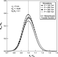
The effect of Brownian diffusive particle trajectory of nanoparticles on the transfer function of the low pressure Differential Mobility Analyzer (LPDMA) was evaluated by a numerical simulation of the Langevin dynamic equation. The results of the simulation were compared with previously reported experimental results (CitationSeto et al. 1997; CitationSeol et al. 2000) and Stolzenburg's transfer function (1988). As the operational pressure decreased, the peak and FWHM (full width of the transfer function at half of its maximum) values of transfer function, as calculated by numerical simulation, were increased, which was not evident from Stolzenburg's transfer function. In comparison with the experiments of Seto et al., discrepancies in the higher electrical mobility regime than from central mobility were found, which could be caused by the incomplete flow control of their LPDMA. However, the transfer function, as calculated by numerical simulation was in good agreement with experimental results reported by Seol et al., performed with the improved LPDMA at well-controlled operation conditions.
1. INTRODUCTION
A Differential Mobility Analyzer (DMA) can be used to measure various aerosol particles that are several orders of nanometers in size. For measurements of ultrafine particles or nanoparticles (particle diameter below 100 nm), the DMA has certain advantages, in that it is able to measure a high number concentrations of particles with high resolution in contrast to other methods.
Most DMAs have been designed and calibrated for aerosol sampling at atmospheric conditions, can also be used at reduced pressure conditions, after appropriate modification. In the semiconductor fabrication industry, nanometer-sized particles formed at low pressure have become a serious problem. The manufacturing of semiconductor devices involves processes that operate over a wide range of operating pressures, from atmospheric to ultra-high vacuum. During processing, particles can be produced by flaking from the walls of the equipment, or by homogenous nucleation resulting from pressure reductions or from gas phase chemical reactions involving gas phase species that produce nonvolatile products. These particles can be deposited on surfaces of semiconductor devices, leading to defects that reduce product yield. Semiconductor manufacturers need to be able to detect nanoparticles at subatmospheric pressures (CitationZiemann et al. 1995). The measurement of atmospheric aerosol particles at high altitudes and on research aircraft also involve reduced pressure conditions. When particle size measurements using DMAs are carried out at altitudes of 10–12 km, ambient pressure may be as low as 200 Torr. However, our understanding of the performance and operation of DMAs at low-pressure conditions is limited (CitationSeifert et al. 2004).
DMA performance in measuring aerosol particles can be described in terms of its transfer function. Measurement of ultra-fine aerosol particles is significantly affected by Brownian random motion that leads to deviations in particle trajectory from the nondiffusive trajectory in DMA, and reduces the resolution of the DMA. Numerous investigators have examined this effect of Brownian diffusion on the performance of a DMA operated at atmospheric pressure conditions by both experimental and numerical methods, leading to improvements that enhance the efficiency of measurement of ultrafine particles. CitationKousaka et al. (1986) studied the effect of Brownian diffusion on the electrical classification of ultrafine particles in a DMA. Particle loss caused by the Brownian diffusive deposition of particles was theoretically evaluated by solving the convective diffusion equation; the calculated results were confirmed by experiments.
Stolzenburg (1998) derived a semi-analytical expression for the DMA transfer function for diffusive particles by considering a Gaussian distribution of particles with distance from their nondiffusive trajectories. The diffusive transfer function was evaluated by integrating the Gaussian distribution over the inlet and outlet flows. Stolzenburg used an empirically determined distortion variant to develop a method that accounts for the broadening of the transfer function that results from flow and field distortions in real instruments. Through a numerical description using the convective diffusion equation, Chen et al. (Citation1997, Citation1998a, Citation1998b) and CitationEichler et al. (1998) modified the inlet slit design to reduce circulation flow inside the inlet slit, and shortened the column length of the DMA, leading to improved resolution in the low nanometer size range. CitationHagwood et al. (1999) evaluated the transfer function of DMA based on particle trajectories using a Monte-Carlo simulation method and compared the findings with Stolzenburg's transfer function. This approach used only random variables in determining the particle displacement to describe the Brownian motion of particles, but did not account for correlations between random variables in velocity and the displacement of particles. CitationFlagan (2004) applied the same method to the development of a new opposed migration aerosol classifier, with the same limitations.
CitationRosell-Llompart et al. (1996) derived an expression for DMA resolution at a high Peclet number (Pe mig ), in terms of flow rates, DMA dimensions, migration Pe mig number, and the slit widths of the inlet and outlet. The expression was experimentally verified using a shortened version of Reischl's DMA. The transfer function was expressed as a Gaussian distribution over the applied voltage, and the value of the DMA resolution was used as a standard deviation of that Gaussian distribution. CitationFlagan (1999) examined the theoretical limits to the resolution of various DMA designs using Stolzenburg's model of the transfer function and showed that the relative contribution of electrophoretic migration to diffusion can be expressed as a function of Pe mig , which can be expressed in terms of particle mobility, DMA dimensions, and flow rate.
CitationSeto et al. (1997) attempted to develop a low-pressure DMA (LPDMA) for the measurement of nanoparticles in the low-pressure range, 65–760 Torr. CitationSeol et al. (2000) improved the performance of LPDMA and extended the pressure range to 200 Pa. They used large radii and short lengths of connecting tubes and designed mass flow meters for use at low pressures to reduce the pressure drop between the DMA and vacuum pumps, which is crucial for low-pressure operation. The LPDMA was also used to investigate an inherently monodisperse standard nanoparticle in the 1-nm diameter range (CitationTanaka and Takeuchi, 2003). To evaluate the performance of LPDMA, it is necessary to have knowledge of the Brownian diffusion effect on particle trajectories. However, our knowledge of the diffusive motion of nanoparticles at low-pressure conditions and its effect on the transfer function of the LPDMA is currently incomplete.
In this study, a numerical evaluation of Brownian diffusion on particle trajectory at low-pressure conditions was carried out, leading to a change in the transfer function of the LPDMA. To obtain Brownian diffusive particle trajectories, we used the Langevin equation based on Brownian dynamic properties. The fluid flow in the classification region of the LPDMA is laminar and continuum at low-pressure condition. The time step that is crucial for the exact calculation of particle trajectories was selected to minimize the inherent numerical error to within tolerable quantities. The results of the simulation were compared with experimental results and Stolzenburg's transfer function.
2. LOW-PRESSURE DMA
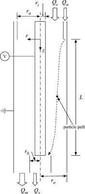
shows a simplified schematic of the DMA used in this study, and the inner and outer radius and the length of the DMA are listed in . The particle trajectory is dependent on the shape of the aerosol inlet slit, since distortions of flow may occur in the vicinity of the inlet slit. In addition, there are other factors that make the transfer function of DMA different from the ideal shape. However, the simplified geometry of the DMA was used, in order to specifically focus on the effect of the diffusive motion of the particle.
TABLE 1 Operating pressure, flow rates, DMA dimensions, and particle diameter used in experiments and numerical simulation, and appropriate Knudsen number of flow and Reynolds number. r i = 25 mm, r o = 33 mm, and Q a = 1 SLM for all cases
The median value for the distribution of electrical mobility of classified particles, Z pc , is a function of the dimensions of the DMA, L, r i , and r o , the applied voltage V, and the flow rate of sheath gas, Q c , given by (CitationKnutson and Whitby 1975)
The electrical mobility, Z p , is also related to the particle diameter, d p , as
2.1 Consideration of Low-Pressure
The dependence of the mean free path of a gas molecule on the pressure, p, is given by
The flow through the classification region is assumed to be fully developed laminar flow. However, if the pressure becomes too low, the flow cannot be assumed to be a continuum. Generally, the continuum assumption of flow can be validated using the value of the flow's Knudsen number. The Knudsen number of flows, Kn f , can be expressed as
2.2 Flow and Electrostatic Field
All DMAs are designed to operate in laminar flow conditions and to avoid turbulent mixing which degrades the performance of the DMA. Further, DMAs are operated at steady and low Mach number flow rates for most applications. Under these conditions, the flow inside the DMA can be assumed to be steady, incompressible and laminar. Based on the principle of the conservation of momentum, the incompressible Navier-Stokes equation (N-S equation) can be applied in this case. In this axisymmetic geometry and with the assumption of fully developed flow, the radial component of the N-S equation vanishes and the axial component can be given by
The electrostatic field for concentric cylinders can be expressed by the Poisson equation. However, the space-charge effect on the electrostatic field can be neglected for low aerosol concentrations that are typically less than 106 particles cm− 3. Thus, the Laplace equation is used in this formulation. In 2-D cylindrical coordinates, the resulting electric field is given by
3. PARTICLE TRAJECTORY
3.1 The Langevin Equation
We used the Langevin equation to calculate the particle trajectory. The ordinary Langevin equation for a Brownian diffusive particle that is in thermodynamic equilibrium with the bath at temperature T and is subject to an external force , is then (CitationErmak and Buckholz 1980)
Using Ermak's method, it is assumed that external forces are constant during the time step. However, the flow velocity and the electrostatic force exerted on particles are dependent on the particle position and are not constant during a given time step. This assumption makes differences in the resulting particle position at the exit of the classification region. Hence, an appropriate decision concerning the size of the time step is important in reducing cumulative errors in the calculation of particle trajectories.
3.2 Transfer Function
The mobility range of particles classified using the DMA, Δ Z p , is given by
4. SIMULATION RESULTS AND DISCUSSION
The flow rates, particle diameter, operational pressure and DMA dimensions used in this simulation are listed in . The assumption that the flow in the DMA is continuum and laminar was confirmed for each condition in advance. In the pressure range tested in this work, the maximum Knudsen number for flow is 4.28 × 10− 3. This value meets the condition, Kn f ≪ 0.1, for the application of continuum assumption. It also meets the criteria for the use of the laminar flow assumption; the maximum value of the Re number is 64.1. Values for Kn f and Re are also listed in .
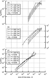
The time step used in solving particle trajectories was selected to minimize the inherent errors of the particle position with respect to deviation due to Brownian motion. Numerically inherent errors in the calculation of particle position are caused by the assumption that the external force is constant during the time step. With the given geometry and operating conditions, the radial exit position of a particle, r e (Δ t), at each time step is calculated using the Langevin equation without the random force term, which specifically accounts for the inherent numerical errors. Without the random force term, differences in particle position as a function of time steps show inherent numerical errors excluding deviations resulting from Brownian motion of the particle. This particle trajectory varies with the size of the time step. The position of the particles becomes accurate with a decrease in the size of the time step. However, there are limits to reducing the size of the time step in applications to real calculations.
The size of time step was selected such that the inherent errors are much less than the deviation produced by Brownian motion. The standard deviation for Brownian motion is
FIG. 2 The deviation ratio of the numerical diffusion to the Brownian diffusion as the time step change for configurations of Seto et al. (a), (b); and Seol et al. (c).
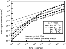
When the observation time of interest is longer than the particle characteristic time, β− 1, particle diffusivity is accurately characterized by continuum techniques using Einstein's particle diffusivity, D, given by
FIG. 3 Comparison of mean-square deviations between the Einstein's relation (lines without circle) and the BDS simulation (lines with circle).
Particle trajectories were obtained by the Langevin equation with BDS. The time step for each condition was taken to satisfy σ N (Δ t)/σ D < 0.01. The particles are assumed to have a single charge and to be spherical in shape. The inlet region of the particles is a concentric cylinder with inner radius r a and outer radius r o . The area π (r o 2 − r a 2), corresponds to the area required for the aerosol flow with the given velocity profile, and the outlet port, r b , is obtained by determining the area needed for the entire aerosol flow to pass between the inner cylinder r i and r b (CitationHagwood et al. 1999). The radial positions to define the inlet and outlet ports were obtained by integrating the flow velocity profile. The values of r a and r b are varied with the flow ratio of aerosol to sheath flow, and listed in . The inlet slit area is divided into 100 concentric rings, and the volume flow of the particles through each ring is calculated. The number of particles starting from each ring is 1000, and the particle is counted if it does not touch either wall and its radial location at the outlet position z = L is smaller than the outlet port, r b . Using the flow fractions of each ring, the number of particles starting from each ring that pass through the outlet is obtained. shows some diffusive trajectories of a particle at the given condition, and all particle trajectories show that particles have random motions caused by collisions with gas molecules. The solid line shows the trajectory of particles that pass the outlet, and are counted. The CPU time needed to calculate one particle trajectory is varied on the time step size, magnitudes and pressure condition. It needed about 24 s in CPU time to run 1000 particle trajectories using a computer has 3 GB RAM and dual 3 Ghz Xeon processors.
FIG. 4 Sample trajectories for 10 nm particles in LPDMA of Seto et al. at Q a /Q c = 0.2 with Q a = 1 SLM and p = 65 Torr. The solid and dotted lines are describing particle trajectory that pass through, or miss the outlet respectively.
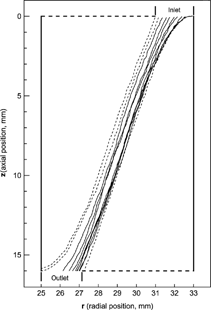
TABLE 2 Values of r a and r b depending on the flow ratio
In this work, we used the dimensionless mobility, [Ztilde] p (= Z p /Z pc ), as an independent variable, because the particle mobility is fixed in this simulation. The central electrical mobility and corresponding applied voltage were obtained from the particle size by Equations (eqEquation1) and (eqEquation2). After calculating the particle trajectory using the Langevin equation and counting the number of particles that penetrated to the outlet, the transfer functions of the 2nd DMA in the tandem DMA system were obtained, and these were compared with previous experimental results (CitationSeto et al. 1997; CitationSeol et al. 2000) and Stolzenburg's transfer function. With the described particle distribution at aerosol inlet, the transfer function of the 1st DMA can be obtained using the particle trajectory simulated with the BDS. The electrical mobility of particles was varied with the applied voltage at the electrode. The rate of penetration of particles was calculated over the ranges of electrical mobility, which changed with the normalized step size (Δ [Ztilde] p = Δ Z p /Z pc = 0.01). The transfer function of the 2nd DMA is calculated by convolution of the transfer function and particle distribution at the inlet of the 2nd DMA with the assumption that the particle distribution at the inlet of the 2nd DMA is kept the same as the distribution at the outlet of the 1st DMA. The transfer function of the 2nd DMA using Stolzenburg's formula is also obtained by the same procedure. For a comparison with experimental findings, a numerical simulation was performed at the same condition as was used in the experiments; flow rates and ratio, i.e., the dimensions of the DMA, operating pressure, and particle sizes used in experiments were also used in the numerical calculation.
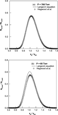
In this simulation, we included an inertial term of particle motion and successions of random force from the force balance, velocity, to position of particle. shows a comparison of the resulting mobility distributions obtained by the Langevin equation and the method used in the report of Hagwood et al. Hagwood et al. provided a validation to neglect the inertia term of particle motion, and there was no significant difference in the resulting mobility distribution at the atmospheric pressure condition. However, there were significant differences in the mobility distributions at the reduced pressure condition. These comparison results showed that the treatment of successions of random force was essential in this kind of simulation as the relaxation time of particle motion is increased with decreases of pressure.
FIG. 5 Comparison of mobility distributions obtained by the Langevin equation and the method used in the report of Hagwood et al. at the pressure was (a) 760 Torr and (b) 65 Torr; Q a = 1 SLM, Q c = 5 SLM, and d p = 5 nm with DMA geometries of Seto et al.
and show a comparison of the transfer function of the 2nd DMA obtained numerically with experimental values reported by Seol et al. and Seto et al. respectively. The transfer functions for the numerical simulation and experimental data for 10 nm particles plotted in were almost identical. The peak values of the transfer function in the numerical simulation were increased with decreasing pressure. Moreover, the peak values for the simulation results became larger than the theoretical maximum value at operational pressures under 400 Pa. With the same flow configuration and particle size, the central electrical mobility where the transfer function has a peak value, was shifted to lower values with decreasing operating pressure. The direction of peak mobility shift in transfer function of the tandem DMA system was opposite to that observed in transfer functions of a single DMA. As we noted, the transfer function of the tandem DMA system consisting of two identical DMAs was obtained by convolution of those transfer functions. As diffusion increases, the transfer function broadens, and the tail of size distribution in the higher mobility regime grows. The convolution of this skewed distribution leads to the shift of value of peak mobility toward to higher mobility. In contrast to the comparison with Seol et al., the experiments of Seto et al. showed a broader transfer function than obtained in the numerical results. In all of the pressure conditions, the numerical and experimental results show a discrepancy in transfer function in the higher electrical mobility regime ([Ztilde] p > 1), and the discrepancies are larger in the case of Seto et al.
FIG. 6 Comparison of the transfer function of the 2nd DMA by numerical simulations (solid line) with the experimental results of Seol et al. at the pressure is 200 (a), 400 (b), 665 (c), and 930 (d) Pa and for the 10 nm size particles only.
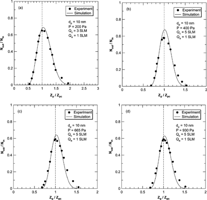
FIG. 7 Comparison of the transfer function of the 2nd DMA by numerical simulations (solid line) with the experimental results of Seto et al. (1998), at the flow ratio is 0.2 (a) and 0.1 for the 5 nm size particles.
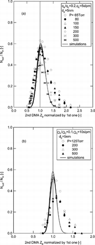
From a comparison of simulation results with the experimental results of Seto et al., some discrepancies were observed in the value of the transfer function in the higher electrical mobility regime. In the experiments of Seto et al., there were lacks in control of pressure drop, leading to destabilize the pressure and flow rate in the vicinity of the sheath outlet. In contrast, Seol et al. developed an experimental system with careful consideration to preventing pressure drop between the DMA and vacuum pumps, which is crucial for a low-pressure operation. Moreover, they used mass flow meters that were specially designed for low pressures, and short lengths of connecting tube with large radii. The large differences in the comparison with the experiments of Seto et al. are caused by pressure instability at the exit of the LPDMA.
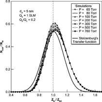
We also performed a comparison of the transfer functions with Stolzenburg's results. , , show the results of the comparison at various experimental conditions. In all cases, Stolzenburg's transfer function remained unchanged with the operational pressure. The shape of Stolzenburg's transfer function was determined by the aerosol flow ratio, the geometrical dimensions of the DMA and the mean-square deviation given by σ2 = G c · [Dtilde]. With the same flow condition and geometry of the DMA, the mean-square deviation due to Brownian diffusion varies with [Dtilde]; G c is fixed at the given flow rate ratio and the geometry of the DMA, the value of G c is unchanged with particle size and operating pressure. The nondimensional diffusion coefficient, [Dtilde] = 2π LD/Q c , used in Stolzenburg's formula varies only slightly with pressure change. The particle diffusivity, D, is inversely proportional to pressure for a particle size range of less than 10 nm and the flow ratio is also inversely proportional to the pressure. As a result, [Dtilde] has almost the same value, and is independent of pressure change. shows the change in the values of D, [Dtilde], and σ with change in operating pressure. As the operational pressure decreased, the value of [Dtilde] converged to a specific value and its maximum difference with the value at atmospheric condition is small compared to its absolute value. Further, since the values of mean-square deviation are determined only by G c and [Dtilde], the values of the mean-square deviation and the resulting transfer functions were almost the same with pressure change. However, the numerical simulations showed changes with pressure change. The peak values for the transfer function from the numerical simulation were higher than those of Stolzenburg's transfer function. Consequently, the half-width of the transfer function was increased as the pressure decreased, although the magnitude of the change was small. As the operational pressure increased to atmospheric pressure, the peak value and shape of the transfer function by numerical simulation appeared to approach Stolzenburg's transfer function.
FIG. 8 Comparison of the transfer function of the 2nd DMA by numerical simulations with the Stolzenburg's transfer function at Q a /Q c = 0.2 and Q a = 1 SLM for 10 nm particles.
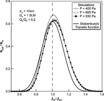
FIG. 9 Comparison of the transfer function of the 2nd DMA by numerical simulations and the Stolzenburg's transfer function at Qa/Qc = 0.2 and Qa = 1 SLM for the 5 nm particles.
5. CONCLUSION
The Brownian diffusive particle trajectory and its effect on the transfer function of the LPDMA were evaluated by means of the Langevin equation. The simulated results were compared with experimental results and Stolzenburg's transfer function. Stolzenburg's transfer function remained constant with pressure change. To the contrary, the transfer function obtained by numerical simulation changed with the operational pressure change. As the pressure decreased, the peak values increased and the corresponding particle mobility changed slightly. The FWHM values for the transfer function also increased with decreasing pressure. Moreover, the simulation results were in good agreement with experimental results reported by Seol et al. performed with an improved LPDMA at well-controlled operating conditions.
The transfer function obtained by numerical simulation was obtained under the assumptions that the particles entering the LPDMA are monodisperse and have a low number concentration, which permits the space charge effect to be neglected. Assessments of polydisperse particle distribution and space charge effects in particle behavior will be needed to describe the behavior of particles more accurately.
NOMENCLATURE
| B 1,B 2 | = |
Random velocity change and displacement |
| C C | = |
Cunningham slip correction factor, dimensionless |
| D | = |
Diffusivity of particles, m2 s− 1 |
| d p | = |
Particle diameter, m or nm |
| e | = |
Elementary electrical charge, C |
| E k | = |
The k-th component of electric field strength, V m− 1 |
| k b | = |
Boltzmann constant, J K− 1 |
| Kn D | = |
Knudsen number for particle, dimensionless |
| Kn f | = |
Knudsen number for flow, dimensionless |
| L | = |
Length of DMA, m |
| l c | = |
Characteristic length scale |
| m p | = |
Particle mass, kg |
| n | = |
Number of elementary charge, dimensionless |
| N k | = |
Particle number concentration at the kth DMA, particles m− 3 |
| p | = |
Pressure, Torr or Pa |
| Q a | = |
Flow rate of aerosol, l min− 1 |
| Q c | = |
Flow rate of sheath gas, l min− 1 |
| r a | = |
Radial position of aerosol flow boundary, m |
| r b | = |
Radial position of sample flow boundary, m |
| r e | = |
Radial exit position of particle, m |
| r i ,r o | = |
Radii of the DMA, m |
| T | = |
Absolute temperature, K |
| t r | = |
Residence time, sec |
| U k | = |
The kth component of gas velocity in the DMA, m s− 1 |
| V | = |
Applied voltage at the center rod, V |
|
| = |
Particle velocity in the DMA, m s− 1 |
| X | = |
Random force exerted on particle |
| Z p | = |
Electrical mobility of particle, m2 s V − 1 |
| [Ztilde] p | = |
Normalized electrical mobility, dimensionless |
| Z pc | = |
The central electrical mobility distribution of particles |
Greek Letters
| α C , β C , γ C | = |
Parameters for Cunningham correction factor |
| β | = |
Friction constant of particle |
| λ | = |
Mean free path of gas molecule, m |
| μ | = |
Gas viscosity, 1.786 × 10− 5 Pa·s for N2 gas |
| ρ f | = |
Density of flow gas, kg m− 3 |
| σ D | = |
Mean square deviation due to the Brownian diffusion, m |
| σ N 2 | = |
Collision diameter of N2 gas molecule (= 0.370 nm at STP) |
Subscripts
| atm | = |
atmospheric conditions |
| r | = |
radial direction |
| z | = |
axial direction |
| 0 | = |
old values of corresponding variable |
| 1 | = |
values of the 1st DMA |
| 2 | = |
values of the 2nd DMA |
| i,o | = |
values for inlet and outlet |
Acknowledgments
The authors thank Dr. Kwang Soo Seol and Dr. Takafumi Seto for discussions and for sharing their experimental results with us. Dr. S. Kim and D. Song express their gratitude from the Brain Korea 21 program of the Ministry of Education for financial support.
REFERENCES
- Allen , M. D. and Raabe , O. G. 1982 . Re-Evaluation of Millikan's Oil Drop Data for the Motion of Small Particles in Air . J. Aerosol Sci. , 13 : 537 – 547 .
- Chen , D. and Pui , D. Y. H. 1997 . Numerical Modeling of the Performance of Differential Mobility Analyzer for Nanometer Aerosol Measurements . J. Aerosol Sci. , 28 : 985 – 1004 . [CROSSREF]
- Chen , D. R. , Pui , D. Y. H. , Hummes , D. , Fissan , H. J. , Quant , F. R. and Sem , G. J. 1998 . Design and Evaluation of a Nanometer Aerosol Differential Analyzer (Nano-DMA) . J. Aerosol Sci. , 29 : 481 – 485 . [CSA]
- Chen , D. R. , Pui , D. Y. H. , Mulholland , G. and Fernandez , M. 1998 . Design and Testing of an Aerosol/Sheath Inlet for High Resolution Measurement with TSI-DMA . J. Aerosol Sci. , 29 : 497 – 509 . [CROSSREF]
- Eichler , T. , de Juan , L. and de la Mora , J. F. 1998 . Improvement of the Resolution of TSI's 3071 DMA via Redesigned Sheath Air and Aerosol Inlets . Aerosol Sci. Technol. , 29 : 39 – 49 . [CROSSREF]
- Ermak , D. L. and Buckholz , H. 1980 . Numerical Integration of the Langevin Equation: Monte Carlo Simulation . J. Comp. Phys. , 35 : 169 – 182 . [CROSSREF]
- Flagan , R. C. 1999 . On Differential Mobility Analyzer Resolution . Aerosol Sci. Technol. , 30 : 556 – 570 . [CROSSREF]
- Flagan , R. C. 2004 . Opposed Migration Aerosol Classifier (OMAC) . Aerosol Sci. Technol. , 38 ( 9 ) : 890 – 899 . [CROSSREF]
- Hagwood , C. , Sivathanu , Y. and Mulholland , G. 1999 . The DMA Transfer Function with Brownian Diffusion Motion a Trajectory/Monte-Carlo Approach . Aerosol Sci. Technol. , 30 : 40 – 61 . [CROSSREF]
- Knutson , E. O. and Whitby , K. T. 1975 . Aerosol Classification by Electric Mobility: Apparatus, Theory, and Applications . J. Aerosol Sci. , 6 : 443 – 451 . [CROSSREF]
- Kousaka , Y. , Okuyama , K. , Adachi , M. and Mimura , T. 1986 . Effect of Brownian Diffusion on Electrical Classification of Ultrafine Aerosol Particles in Differential Mobility Analyzer . J. Chemical Eng. Japan , 19 : 401 – 407 .
- Rosell-Llompart , J. , Loscertales , I. G. , Bingham , D. and Mora , J. F.d. l. 1996 . Sizing Nanoparticles and Ions with a Short Differential Mobility Analyzer . J. Aerosol Sci. , 27 : 695 – 719 . [CROSSREF]
- Seifert , M. , Tiede , R. , Schnaiter , M. , Linke , C. , Möhler , O. , Schurath , U. and Ström , J. 2004 . Operation and Performance of a Differential Mobility Particle Sizer and a TSI 3010 Condensation Particle Counter at Stratospheric Temperature and Pressures . J. Aerosol Sci. , 35 : 981 – 993 . [CROSSREF]
- Seol , K. S. , Tsutatani , Y. , Camata , R. P. , Yabumoto , J. , Isomura , S. , Okada , Y. , Okuyama , K. and Takeuchi , K. 2000 . A Differential Mobility Analyzer and A Faraday Cup Electrometer for Operation at 200-930 Pa Pressure . J. Aerosol Sci. , 31 : 1389 – 1395 . [CSA] [CROSSREF]
- Seto , T. , Nakamoto , T. , Okuyama , K. , Adachi , M. , Kuga , Y. and Takeuchi , K. 1997 . Size Distribution Measurement of Nanometer-Sized Aerosol Particles using DMA under Low-Pressure Conditions . J. Aerosol Sci. , 28 : 193 – 206 . [CROSSREF]
- Stolzenburg , M. R. 1988 . An Ultrafine Aerosol Size Distribution Measurement System , Minneapolis : University of Minnesota . Ph.D. Thesis
- Tanaka , H. and Takeuchi , K. 2003 . Experimental Transfer Function for a Low-Pressure Differential Mobility Analyzer by Use of a Monodisperse C60 Monomer . J. Aerosol Sci. , 34 : 1167 – 1173 . [CROSSREF]
- Zhang , S.-H. and Flagan , R. C. 1996 . Resolution of the Radial Differential Mobility Analyzer for Ultrafine Particles . J. Aerosol Sci. , 27 ( 8 ) : 1179 – 1200 . [CROSSREF]
- Ziemann , P. J. , Liu , P. and Rao , N. P. 1995 . Particle Beam Mass Spectrometer of Submicron Particles Charged to Saturation in An Electron Beam . J. Aerosol Sci. , 26 : 745 – 756 . [CROSSREF]
![FIG. 11 The changes of values of D, [Dtilde], and σ with the operating pressure change at Q a /Q c = 0.2 for the 10 nm particle.](/cms/asset/b5d8fa66-5786-40b8-a7cf-2a7eb61375d8/uast_a_118222_o_f0011.gif)