Aerosol particles formed from the bursting of small gas bubbles emitted from the anode and cathode electrodes during electrolytic chrome plating were measured with a laboratory apparatus. The measured aerosol particle emission factors were about 5.15 mg particles/amp-hour or 3.81 mg Cr+ 6/amp hour. The cathode gases generated more particles on a gas volume basis with 20 mg particles/liter hydrogen gas evolved from the cathode compared to 1 mg particles/liter oxygen gas evolved from the anode. With about 35% more cathode hydrogen gas evolved than anode oxygen gas evolved and with the much greater particle emissions caused by the cathode hydrogen on a gas volumetric basis, the aerosol particle emissions from the cathode bubble bursting were about 97% of the total particle mass emissions. The particle size distributions measured from the cathode had a mass median aerodynamic diameter of about 38 μ m whereas the anode mass median particle diameter was about 8 μ m. The anode particle mass size distribution was bimodal with peaks at about 0.6 and 24 μ m diameter. The cathode particle mass size distribution was trimodal with peaks at 2.5, 9, and about 60 μ m diameter.
INTRODUCTION
The objectives of this article are to present the results of a laboratory chrome plating study which measured the volume of gases generated from the electrodes and the aerosol particle emissions resulting from the bursting of the gas bubbles evolved from the anode and cathode electrodes. This research on the chromic acid plating process has significance towards understanding the aerosol particle formation process and the potential reduction of aerosol particle emissions which contain toxic hexavalent chromium (hexavalent chromium plating). In January 1995 the United States Environmental Protection Agency established air pollutant emission limits for chromium compounds from new and existing sources of chromium electroplating and anodizing sources. CitationKoropchak and Roychowdhury (1990) reported particle size distributions measured with an 8-stage Marple cascade impactor in a small chrome electroplating shop.
Chrome Plating
The chrome plating process electrolytically plates chromium onto a metal using a chromic acid solution of about 20–25% by weight CrO3 in water and voltages in the 10–30 volt dc range. The anode is typically a lead or lead alloy material and the cathode is the substance upon which the chrome is electrolytically deposited. Plating solutions may vary in hexavalent chromium concentration and other additives depending upon the plating operation. CitationCanning (1970) reported that a typical chrome plating solution consists of 250 grams CrO3 per liter and 2.5 grams H2SO4 per liter.
Chromium plating was developed by Geuther in about 1857 in Germany as reported by CitationBlum and Hogaboom (1930). CitationZaki (1990) reported that due to the typically low cathode plating efficiency (10–20%), a large amount of H2 is developed at the cathode part being chrome plated. However, no volumetric measured gas evolution data were found in the literature for chrome plating. van Troostwijk and Deimann (1789) reported on the electrical decomposition of water into H2 and O2. Later CitationFaraday (1834) reported on the quantitative aspects of water electrolysis. Faraday's law states that the quantity of any element liberated at either the anode or cathode during electrolysis is proportional to the quantity of electricity conducted. The electrolysis of aqueous acid solutions with platinum electrodes is related to the oxidation and reduction reactions in water shown below:
Aerosol Formation
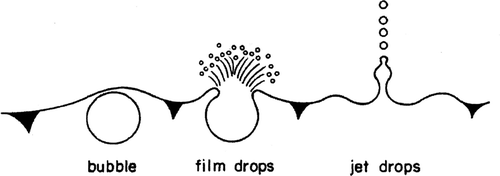
The hydrogen and oxygen gases which are formed during the chrome plating process evolve as small gas bubbles at the metal surfaces of the anode and cathode electrodes. When these small bubbles rise to the liquid solution surface and burst, aerosol droplets are formed. CitationKientzler et al. (1954) and CitationResch et al. (1986) have reported on studies of air bubble bursting experiments conducted using air bubbles released in fresh and salt water. High-speed photographs of the bursting of a single air bubble have shown that the bubble bursting produces film droplets and jet droplets. The film droplets are formed first by the bursting of the bubble as it reaches the solution surface. Upon the collapse of the bubble cavity, jet droplets are produced. This is shown schematically in.
TEST APPARATUS AND PROCEDURES
Gas Evolution Measurements
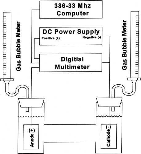
A schematic diagram of the gas evolution laboratory experimental apparatus is presented in and shows that a 56-volt dc 10 amp Kenwood regulated power supply was connected to the all-glass electrolytic cell with two 50 mL modified buret gas bubble meters serving to measure the volumes of gases evolved. The current and voltage were measured by a Fluke multimeter and the readings were recorded with a computer.
Pretest preparations included mixing the aqueous solutions, preparing the electrodes (copper cathode and lead anode), cleaning the glassware, and setting up for the test run. Graduated cylinder liquid volumes, bubble meter readings, temperatures of the room air, and barometric pressure were recorded. A test run was of 4–40 minute time duration and gas volumes, bubble meter readings, temperature, barometric pressure, time, amperage, and voltage were recorded on a data sheet every 15–60 seconds.
Aerosol Particle Emissions Apparatus
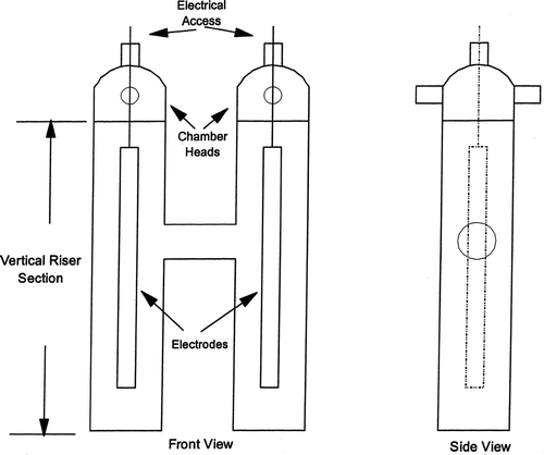
A schematic of the H-cell laboratory chrome plating apparatus used for the measurements of the plating aerosol emissions is shown in. The H-cell design enabled the separation of the anode and cathode gas bubbles (and resultant aerosols) and included two vertical 10 cm diameter cylindrical tube cells (risers) connected by a 6 cm diameter horizontal cylindrical tube. The two vertical cells were constructed from 100 mm OD × 2.4 mm wall glass tubing with flat glass fused to the bottom of each riser. The plating solution level was about 3.5 cm below the top rim of the ground glass outer joints.
Identical chamber heads were fitted into the ground glass fittings at the top of each chamber. The total aerosol mass emissions were collected using open faced 47 mm diameter filter holders with glass fiber filters. The filter holders were attached to the glass tubes which extended from opposite sides of the chamber heads.
The size distributions of the aerosol particles emitting from the cathode and anode sides of the H-Cell apparatus were measured separately using cascade impactors. A 13 jet stage version of the Pilat (University of Washington) Mark 20 cascade impactor and a 15 jet stage version of the Pilat (University of Washington) Mark 10 cascade impactor were used to measure the size distributions of the aerosols from the cathode side of the plating test apparatus. A 7 jet stage Pilat (University of Washington). Mark 3 cascade impactor was used to sample the aerosols from the anode side. Most of the air sampling flow rates were about 5.6 liters/min (0.2 acfm) which is lower than the normal gas sampling flow rate and this lower sampling flow rate was used to reduce turbulent losses of aerosol particles to the walls of the apparatus. The inlet to the cascade impactors (first impaction jet stage) consisted of straight bore nozzles; 2.033 cm (0.8125 inch) diameter on the Mark 20, 1.27 cm (0.5 inch) on the Mark 10 and Mark 3. Gas was sampled from each chamber head for the aerosol particle mass emission measurements (47 mm filter holders) and the aerosol size distribution measurements (cascade impactors) with separate vacuum pumps connected to separate dry gas meters.
A lead strip (15 cm long, 1.9 cm wide, and 0.3 cm thick) was used as the anode. The copper cathodes used for all the tests were cut from a copper sheet (alloy 110, 99.9% Cu) and each cathode was 30.5 cm in length and 2.5 cm in width. Prior to each test, the copper cathodes were cleaned with steel wool and the lead anodes with a damp cloth. The chrome plating tests were conducted at a constant voltage and amperage and were monitored using a Fluke Model 45M dual channel multimeter. A computer program controlled the multimeter settings and recorded the amperage, voltage, and chrome plating time for each test.
Aerosol Particle Emissions Measurements
The plating solution was made in batches by adding 750 grams of CrO3 (Aldrich Chemical 99.9%) and 7.5 g of H2SO4 (Baker Reagent 98%) to 3 liters of deionized water. Reeve Angel 934 A/H glass fiber filters were used as the filter media in each of the 47mm filter holders. The outlet filters (collecting filters) were prepared by heating in an oven at 194°F for 24 hours prior to testing and then desiccating for 1 hour before weighing. All weighing was conducted using an electronic balance with a resolution of 0.002 mg (Mettler Model AT-20). The filter samples were analyzed for Cr+ 6 with NIOSH Method 7600 which involves the use of visible absorption spectrophotometry to measure the absorbance at 540 nm of the Cr+ 6 reacted with a diphenylcarbazide solution. Potassium dichromate solutions were used to make the spectrophotometer calibration curve. Total chromium concentrations were measured using atomic absorption.
Stainless steel foil substrates were used for collecting the aerosols downstream of each jet stage in the University of Washington cascade impactors and Reeve Angel 934 AH glass fiber filters was used for the back up filters. The stainless steel substrates were cleaned, dried, and then desiccated for 24 hours prior to initial weighing. The glass fiber back up filters were also desiccated for 24 hours. The initial and final weighings were conducted using an electronic balance having a resolution of 0.002 mg (Mettler Model AT-20).
RESULTS OF THE PLATING TESTS
Volumes of Gases Emitted
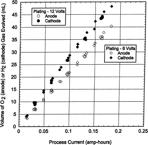
For chrome plating the copper cathode volume of H2 gas evolved was about 35% more than the lead anode volume of O2 gas evolved, as is shown in and this is not in agreement with water electrolysis which shows that the H2 gas volume evolved is twice the O2 gas volume evolved (Equation [Equation3]).
The measured volumes of anode O2 gas versus current usage were about 99% of that theoretically predicted by Equation (Equation5) for oxygen evolution during water electrolysis. The measured cathode H2 gas volumes in were about 61% of the H2 gas evolution volumes theoretically predicted by Equation Equation4.
Particle Emissions Related to Electrical Power Used
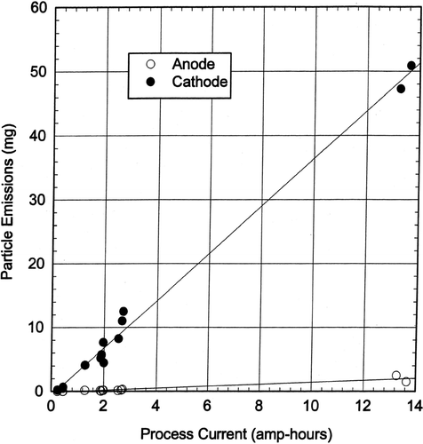
The filter collected aerosol particulate weights from the anode electrode ranged from 0.002 to 2.474 mg and the cathode weights ranged from 0.214 to 50.886 mg. The ratio of the cathode aerosol mass collected to the anode aerosol mass collected had an average of 65.7. presents the chrome plating aerosol particle emissions from the anode and cathode electrodes expressed as milligrams aerosols versus process current (amp-hours). The particle mass emission rate from the cathode was linearly related to the process current at a rate of about 5 mg particles/amp-hour. The particle mass emission rate from the anode was linearly related to the process current at a rate of about 0.15 mg/amp-hour. The aerosol particle generation rate on a weight basis was about 97% from the cathode and 3% from the anode.
Aerosol Particle Emissions Related to Gas Evolution
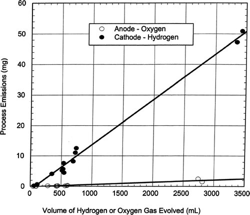
The aerosol particle emission rates from chrome plating are linearly related to the gas evolution rates as is shown in which presents the plating emissions from the anode and cathode electrodes expressed as milligrams particles versus the volume of hydrogen (cathode) or oxygen (anode) gas evolved. The lines in are least squares fit to the data points. The volumes of hydrogen and oxygen gases were calculated from Equations (Equation4) and (Equation5), respectively. The particle emissions from the cathode increased linearly at a rate of about 0.02 mg/mL of hydrogen gas evolved (20 mg/liter H2). The particle emissions from the anode increased at a rate of about 0.001 mg/mL of oxygen gas evolved (1 mg/per liter O2). The cathode H2 gas generated about 20 times as much aerosol particle mass emissions as the anode O2 on a gas volumetric basis.
Plating Aerosol Particle Size Distributions
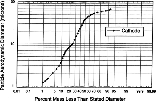
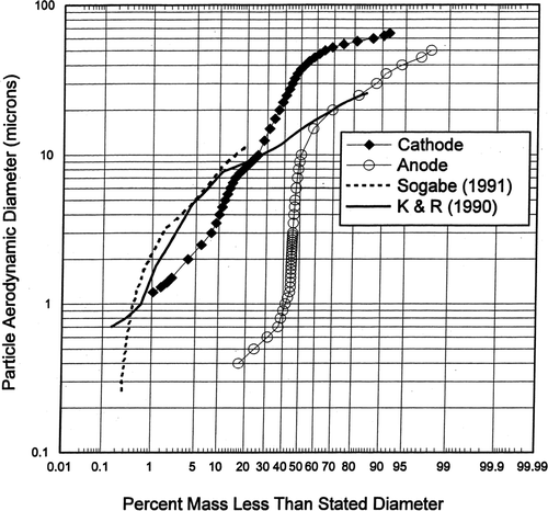
The cascade impactor tests were conducted at similar gas sampling rates which resulted in the jet stage cut diameters or d50s being very similar (for each cascade impactor) and this enabled the resulting size distributions to be combined and averaged for each cascade impactor. More distribution graph plotting points were used than there were cascade impactor jet stage d50s and hence the curves are smoothed. The averaged aerosol particle size distribution from 11 tests of the cathode side (measured with the University of Washington Mark 10 and Mark 20 cascade impactors) had a mass median diameter of about 38 μ m as shown in.
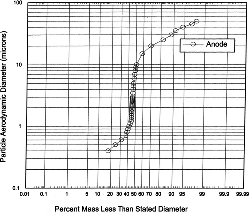
presents the averaged anode particle size distributions of 11 tests (measured with the University of Washington Mark 3 cascade impactor) and shows a mass median diameter of about 8 μ m.
Hexavalent Chromium Content of Filtered Particles
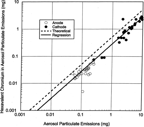
The results of chemical analysis for the amount of hexavalent chromium in the aerosol particles sampled from the anode and cathode using the 47 mm open faced filters are presented in. The data have been plotted as milligrams hexavalent chromium (on the filter) versus total aerosol particulate (on the filter). The weight ratio of Cr+ 6/CrO3 is 52.01/100.01 or about 0.52 and the 45-degree dashed line in shows the case in which 52% by weight of the CrO3 aerosol particles are composed of hexavalent chromium. About 38.5% by weight of the aerosol particles collected on the 47 mm filters were hexavalent chromium and in the solid linear regression line for the analyses data points is about 74% of the theoretical dotted line
DISCUSSION
Particle and Chromium Air Pollutant Emission Factors
The uncontrolled aerosol particle weight and chromium air pollutant emission factors measured during this study are presented in along with emission factors reported in the literature. CitationSogabe (1991) reported a total particulate emission factor of 7.82 mg particles per amp-hour from a hard chrome plating process tank upstream of the emissions control device. This total particulate emission factor of 7.82 mg particles/amp-hour was nearly equal to the sum of the total chrome (2.89 mg/amp-hour) and total hexavalent chrome (4.28 mg/amp-hour). The emission factors presented in a 1989 USEPA document (CitationUSEPA “Locating and Estimating Air Emissions From Sources of Chromium, Supplement,” Research Triangle Park, NC, August 1989) were 9.8 mg total chrome/amp-hour for hard chrome plating operations and 1.6 mg total chrome/amp-hour for decorative chrome plating operations. These USEPA emission factors were average emission factors developed from the emission source tests of various industrial chrome plating operations across the United States. The total particulate and hexavalent chromium emission factors from our laboratory study are within the range of the emission factors reported in the literature.
TABLE 1 Chrome plating emission factors
Size Distributions of Particles Emitted from Chrome Plating
presents a comparison of the averaged aerosol particle size distributions measured from two industrial chrome plating operations with the averaged cathode and averaged anode aerosol size distributions measured in this study. CitationSogabe (1991) reported on measurements of the size distribution of particles emitting from an industrial chrome plating facility using a Pilat (University of Washington) Mark 3 cascade impactor and the curve shown is an average of six tests representing the particle size distributions chemically analyzed by inductively coupled plasma (ICP) as total chromium. CitationKoropchak and Roychowdhury (1990) reported particle size distributions measured in the industrial chrome plating facility's room air using a Marple cascade impactor (Model 298, Andersen Samplers). Their particle size data has a mass median diameter of about 15 μ m and is an average of two tests representing the total chrome size distribution. The data from our study show the average of one Mark 10 and five Mark 20 University of Washington cascade impactor size distributions of cathode plating emissions tests and the average of eleven Mark 3 University of Washington cascade impactor tests for the anode emissions. The mass median diameter of the cathode aerosol was about 38 μ m compared to about 8 μ m for the anode. With the laboratory anode emissions being about 3% by weight of the total particle emissions, the overall size distributions measured in the exhaust ducts from industrial chrome plating operations are probably dominated by the cathode particle emissions. It can be seen in that the two industrial plating particle size distributions are somewhat similar to the laboratory cathode size distributions, especially in the 1–10 μ m diameter range. The larger particles in the 15–60 μ m diameter range measured during our laboratory study resulted from special care being taken to sample and size these larger particles (which are typically removed from the air due to impaction or sedimentation that occurs shortly after these particles are formed by the gas bubble bursting).
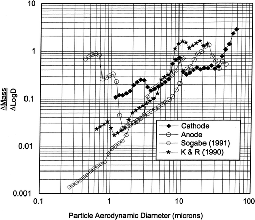
Plotting the particle size distributions in the Δ Mass/Δ logD format in showed that the size distributions have a large particle peak in the 10–24 μ m diameter range. The anode particle size distribution is bimodal with peaks at about 0.6 and 24 μ m. The Koropchak and Roychowdhury size distribution is also bimodal with peaks at about 0.9 and 10–20 μ m. The difference in the particle size distributions between the cathode and anode along with the significantly fewer particles generated by the anode imply a difference in the particle formation and/or generation phenomena. It would appear that the anode-cathode differences observed during our lab experiments were: (1) the diameter of the gas bubbles, (2) the lesser gas volumetric rate evolved from the anode, and (3) the molecular weights of the cathode hydrogen and the anode oxygen. The cathode (hydrogen) bubbles appeared to be smaller in diameter than the anode (oxygen) bubbles. The question remains as to why the cathode hydrogen gas generated about 20 times more particle mass emissions per liter of gas evolved than the anode oxygen gas. Is it because the smaller diameter cathode hydrogen bubbles produce more jet droplets than film droplets and in general these jet droplets are larger than the film droplets, as reported by CitationResch and Afeti (1991) from their seawater studies?
CONCLUSIONS
This research has shown that during the plating of chromium onto copper, the evolution of O2 gas is about as predicted for water electrolysis, but the H2 evolution from the cathode (part being plated) is reduced to about 60% of the volume predicted, probably due to the plating reaction of Cr+ 6 reduction to metallic Cro. The aerosol particle size distributions from the cathode of the laboratory plating apparatus had a mass median diameter of about 38 μ m which was somewhat larger than the total (anode and cathode) size distributions reported in the literature. The particles emitted from the anode were considerably smaller with a mass median diameter of about 8 μ m and the particle mass was bimodal with peaks at about 0.6 and 24 μ m diameter. The aerosol particle mass generated by the cathode hydrogen was about 20 mg/liter hydrogen gas compared to about 1 mg/liter oxygen gas from the anode. The particle process concentrations measured from our laboratory chrome plating apparatus averaged about 5 mg particles/amp-hour which was within the range of 1.9–9.8 mg particles/amp-hour emission factors reported in the literature. This data on the gas evolution and aerosol particle emissions from the chrome plating electrolytic process should improve the understanding of the formation of toxic air pollutants generated by gas bubbles bursting. This information may be useful in the development of methods and equipment to significantly reduce these aerosol particle emissions.
This study was supported in part by the Boeing Company, Seattle.
REFERENCES
- Blum , W. and Hogaboom , G. B. 1930 . Principles of Electroplating and Electroforming, , 2nd Ed. , p. 289 New York : McGraw-Hill .
- Canning , W. 1970 . Canning Handbook on Electroplating, , 21st Ed. , Edited by: Canning , W. England : Birmingham .
- Faraday , M. 1834 . On Electrochemical Decomposition . Philosophical Transactions , 124 : 77 – 111 . [CSA]
- Kientzler , C. , Arons , A. , Blanchard , D. and Woodcock , A. 1954 . Photographic Investigation of the Projection of Droplets by Bubble Bursting at a Water Surface . Tellus , 6 : 1 – 7 . [CSA]
- Koropchak , J. and Roychowdhury , S. 1990 . Evidence for Aerosol Ionic Redistribution Within Aerosols Produced by Chrome Electroplating: . Environ. Sci. & Technol. , 24 : 1861 – 1863 . [INFOTRIEVE] [CSA] [CROSSREF]
- Resch , F. , Darrozes , J. and Afeti , G. 1986 . Marine Liquid Aerosol Production From Bursting of Air Bubbles . J. Geophysical Research , 91 : 1019 – 1029 . [CSA]
- Resch , F. and Darrozes , J. Liquid Aerosol Formation By Air Bubble Bursting, Aerosols: Formation and Reactivity . Proceedings 2nd Int. Aerosol Conf. pp. p. 79 – 82 . Berlin : Pergamon Press .
- Resch , F. and Afeti , J. G. 1991 . Film Drop Distributions from Bubbles Bursting in Seawater . J. Geophys. Res. , 96 : 10681 – 10688 . [CSA]
- Sogabe , M. N. 1991 . Characterization of Airborne Chromium Emissions from Hard Chromium Plating Tanks , Master of Science in Civil Engineering Thesis Department of Civil Engineering, University of Washington .
- USEPA . 1984 . Locating and Estimating Air Emissions From Sources of Chromium: EPA-450/4-84-007g, Research Triangle Park, NC, July 1984[CSA]
- USEPA . 1984 . Health Assessment Document for Chromium. EPA-600/8-83-014F, Research Triangle Park, NC, August 1984[CSA]
- USEPA . 1989 . Locating and Estimating Air Emissions From Sources of Chromium (Supplement). Research Triangle Park, NC, August 1989[CSA]
- USEPA . 1993 . Chromium Emissions from Chromium Electroplating and Chromic Acid Anodizing Operations—Background Information for Proposed Standards. Volume 1, EPA-453/R-93-030a, Research Triangle Park, NC, July 1993[CSA]
- USEPA . 1995 . National Emissions Standards for Chromium Emissions from Hard and Decorative Chromium Electroplating and Chromium Anodizing Tanks . Federal Register , Vol. 60 ( No. 18 ) : pp. 4948 – 4993 . Jan. 25, 1995.[CSA]
- van Troostwijk , P. and Deiman , J. R. 1789 . On a Manner to Decompose Water Into Inflammable Air and Vital Air . J. Phys. , 35 : 369 – 378 . [CSA]
- Zaki , N. 1990 . Risk Reduction in Chromium Emissions . Metal Finishing , 88 : 99 – 102 . [CSA]
