A particle-laden turbulent flow through a square duct was simulated using a direct numerical solution of the Navier-Stokes equations coupled with Langrangian particle tracking. Computations of particle transport were employed to elucidate the mechanisms by which particles with varying inertia deposit to the walls of a square duct. Gravity was neglected and a one-way coupling was assumed between the particles and the fluid. The computational results demonstrate that, although the aerosol penetration through a square duct is not significantly different than through a circular pipe, there exist differences in the transport and deposition mechanisms. Most notably, the off-axis secondary flows unique to the square duct preferentially deposit higher-inertia particles closer to the corners of the duct. By contrast, the same secondary flows act to suppress the deposition of lower-inertia particles to the duct corners by efficiently transporting them back towards the duct core before deposition can occur.
INTRODUCTION
The deposition of particles suspended in a turbulent flow has been widely studied over the last fifty years, beginning with the pioneering work of CitationFriedlander and Johnstone (1957). Historically, the primary motivation for studying deposition in internal flows was to understand the transport of particles through aerosol sampling tubing. Consequently, the bulk of the literature concerns the turbulent flow through ducts having circular or annular cross section. More recently, there has been increasing interest in the turbulent transport of particles through ducts having rectangular cross section due to the relevance of such flows to ventilation systems in buildings (CitationSippola and Nazaroff 2003). Understanding deposition in these more irregularly shaped ducts is critical to evaluating the penetration of outdoor air pollution to indoor environments and the recirculation of pollutants and allergens within buildings. Unfortunately, the flow complexities introduced by corners present in the duct cross section has precluded a rigorous theoretical analysis of deposition in such flows. In the present study, we seek to understand the rates and mechanisms of turbulent deposition in ducts of square cross section, focusing on the role of the turbulence-driven secondary flows that develop in the corners of the duct.
Surprisingly, the turbulent deposition of particles in circular pipes was not thoroughly understood for decades despite extensive experimental data. It was believed that the deposition rate could be fully described by the flow very close to the wall, and that the inertia-dependent response to near-wall coherent structures was completely responsible for the observed inertia dependence of the deposition rate. CitationFriedlander and Johnstone (1957) were the first to point out the importance of inertia to the deposition of particles suspended in turbulent flows. It was postulated that deposition was driven by flow a finite distance away from the wall, where particles acquired enough momentum from turbulent eddies to fly through the viscous sublayer and impact the wall. Over the next few decades, this so-called “free-flight” deposition model was verified through experimental measurements of the input and output concentrations (C in and C out) of a monodisperse aerosol flowing through a pipe. From these measurements, a particle mass flux, J w , to the wall may be defined, from which one may calculate a characteristic velocity associated with deposition:
CitationBrooke et al. (1994) addressed this controversy in a direct numerical simulation of turbulent pipe flow coupled with Lagrangian particle tracking. The authors of that study note that progress in the development of deposition models beyond the free-flight model was hindered by the lack of detailed information provided by existing experiments. Consequently, they used computations to demonstrate that the enhanced wall deposition rate could be attributed to the inertia-dependent transport of particles from the core of the pipe to the near-wall region, where they tended to concentrate. The excessively high concentration of particles near the wall coupled with the lower turbulence intensity present in that region yielded the deposition rates similar to those observed for decades. In the absence of a lateral mean flow, particles migrate from the core to the walls by turbulent diffusion and, in the case of finite-inertia particles, by turbophoresis—the inertia-dependent process by which particles travel down a gradient of turbulence intensity. It is turbophoresis that is responsible for the preferential concentration of higher-inertia particles close to the wall.
A formal theory of particle deposition in a circular pipe including turbophoresis was presented by CitationYoung and Leeming (1997), who assumed a particle phase continuum, and solved the Reynolds-averaged mass and momentum conservation equations. This model represents a valuable progression from conventional free-flight models, because it describes the relative contributions of diffusive and turbophoretic transport throughout the bulk of the flow. Unfortunately, this model cannot be easily applied to deposition in the presence of off-axis secondary mean flows, such as those present in a square duct.
There exist several computational studies focusing on turbulent single phase flow through a square duct including direct numerical simulations (CitationGavrilakis 1992; CitationHuser and Biringen 1993) and large eddy simulations (CitationMadabhushi and Vanka 1991; CitationKajishima and Miyake 1992; CitationVazquez and Metais 2002). All of these demonstrate the turbulence-driven secondary flows that act to transfer fluid momentum from the duct core towards the walls. There exist only two computational studies of particle-laden turbulent flow in a square duct. The first, an LES study reported by Winkler et al. (2004), focuses on the preferential concentration of finite-inertia particles, especially near the walls of the duct. The second, a DNS study recently reported by the authors of this study (CitationSharma and Phares 2006), focuses on longitudinal and lateral single particle-and pair-dispersion statistics. That study demonstrated that the secondary flows act in combination with turbophoresis to transport particles between the duct core and the walls. The present study represents the first computations of particle deposition in a turbulent square duct flow. Here, we focus on the rate of deposition as a function of the location of initial particle release, and the spatial distribution of deposited particles along the duct walls.
NUMERICAL PROCEDURE
Flow Simulation
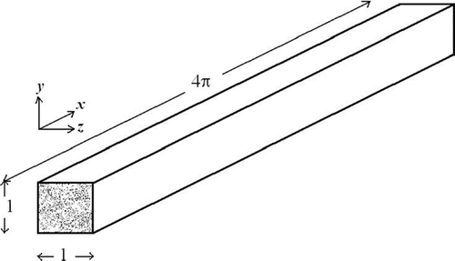
The numerical solution of the Navier-Stokes equations and subsequent flow verification have been detailed in the previous study (CitationSharma and Phares 2006), so only the main points are summarized here. The straight square duct, shown in , is bounded by no-slip walls in the cross-stream directions and the flow is assumed to be periodic in the streamwise direction. The characteristic scales are the duct hydraulic diameter, h, equal to the length of each side of the square duct, and the average friction velocity, u τ a , which is known from the imposed static pressure gradient, Π. With this scaling, the dimensionless equations governing fluid flow may be written
The friction Reynolds number, Reτ = hu τ a /ν, for the simulations presented here is equal to 300 corresponding to a bulk Reynolds number, Re b ∼ 4410. All quantities presented throughout this paper are made dimensionless using the characteristic quantities, h and u τ a , unless denoted with the superscript “+”, which indicates wall units. The dimensions of the square duct are thus 4π × 1 × 1 (see ), or L x + = 3770 and L y + = L z + = 300, in wall units. The discretized governing equations are solved on a uniform Cartesian grid (327 × 195 × 195) totaling 12.43 million computational grid points and the grid resolution is Δ x + = 11.67 in the streamwise direction, and Δ y + = Δ z + = 1.57 in the wall-normal directions. The grid is staggered, so that the first grid point away from the wall is located at Δ y +/2 = Δ z +/2 = 0.79 wall units. The Kolmogorov length scale for this flow based on the volume-averaged dissipation is estimated to be a little over 2 wall units (CitationGavrilakis 1992). The dimensionless integration time step was Δ t = 1.5 × 10− 4 or equivalently Δ t + = 4.5 × 10− 2. The inertial and viscous terms in the momentum equations were approximated in the interior of the flow domain by fourth-order accurate central differences, and all other spatial derivatives in the Eulerian equations of motion are at least second-order accurate. Near the boundaries, all derivatives are second-order accurate with the exception of inertial terms for which a third-order accurate upwind-biased formula was used.
The low Reynolds number turbulent flow was simulated starting from perturbed laminar flow initial conditions. The perturbed flow field was allowed to evolve until the flow became fully developed and statistically stationary. This numerical procedure was verified through comparisons with previous DNS and LES results on similar geometries (see CitationSharma and Phares 2006 for details).
Particle Tracking
Although a number of forces may act on a small particle suspended within a turbulent flow (most notably the Stokes drag force, gravity, and the Saffman lift force), only the Stokes drag is considered here. This approach is similar to that presented by CitationBrooke et al. (1994) for particle tracking in a circular pipe. Gravity is neglected in order to better resolve the role of the secondary flows on deposition. The shear-induced Saffman lift force (CitationSaffman 1965) is also neglected because it only assumes non-trivial magnitudes in the viscous sublayer (CitationMcLaughlin 1989). CitationWang et al. (1997) reported that neglecting the lift force resulted in only a slight reduction in the deposition rate computed from DNS simulations.
The dimensionless force balance equation takes the form
The governing equations of particle motion are integrated using a fourth-order accurate Runge-Kutta method and a small fixed time step equal to the Eulerian flow advancement time step. Eulerian fluid velocities at intermediate points in the computational domain are determined using a tricubic interpolation scheme (CitationRovelstad et al. 1994). Periodicity was assumed in the streamwise direction for particles as well, allowing particle tracking over larger displacements in the x-direction. A particle was considered to deposit when it reached a distance from the wall equal to or less than its radius determined by Equation (Equation5).
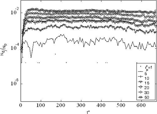
Two types of initial spatial particle distributions were used for the computations, to which we will refer as case A and case B. Case A features the release of 64,000 particles randomly distributed throughout the flow domain. Case B features the release of 120,428 particles uniformly distributed throughout planes located at a specified height, y 0 +, above each of the four duct walls (thus totaling 481,712 particles per simulation). In each case, the initial particle velocity was set equal to the Eulerian fluid velocity at that point and the total simulation time was 675 time wall units. Details of all of the simulations are listed in and for case A and case B, respectively.
TABLE 1 Particle transport simulation parameters for Case A—particles released at random locations throughout the flow domain
TABLE 2 Particle transport simulation parameters for Case B—particles released in planes located at specified heights above the walls
RESULTS
Deposition Rate
In accordance with previous studies of particle deposition, we have computed the deposition velocity, k d +, for a release of particles randomly distributed throughout the duct (case A). For monodisperse particles, the dimensionless deposition velocity may be written
FIG. 3 Computed deposition velocities from case A versus dimensionless particle relaxation time. The dashed line represents the envelope around the circular pipe data compiled by CitationYoung and Leeming (1997).
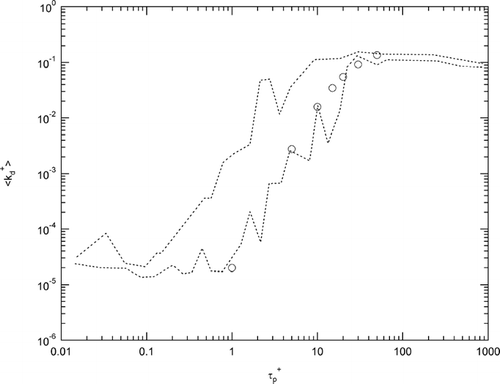
The most notable feature of is that there does not appear to be a significant difference between deposition in a circular pipe and a square duct for the values of particle inertia considered here, all of which lie in the diffusion-impact and inertia-moderated regimes. The data point corresponding to the smallest value of particle inertia (τ p + = 1) is slightly below the data envelope, suggesting that deposition is less likely in a square duct for low-inertia particles than in a circular duct. This is consistent with a previous observation that low-inertia particles are more likely than high-inertia particles to be carried back into the core of the square duct by the mean secondary swirling flow (CitationSharma and Phares 2006). By contrast, higher inertia particles are efficiently carried to the walls where they are more likely to deposit or accumulate near the wall in regions of high strain rate.
Deposition Patterns
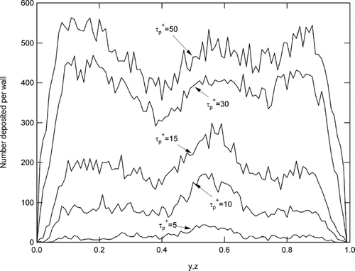
The problem with using deposition velocity to describe particle transport to the walls of ducts having a non-circular cross-section is that local effects are ignored. Whereas deposition along the inner wall of a circular pipe is relatively uniform, the non-uniform deposition patterns along the walls of the square duct suggest deposition mechanisms that differ from a circular pipe, despite the fact that the overall penetration appears to be similar.
displays the deposition patterns computed along the walls of the duct for five values of particle inertia from the case A simulations. The data in are presented as the number of particles deposited within small bins along the wall (Δ y or Δ z), averaged along the total streamwise length of the duct and among all four walls. Thus the abscissa represents the distance along any wall in the direction normal to the streamwise direction, and y,z = 0 or 1 correspond to corners. The plot reveals that there exist definite deposition patterns, and that these patterns are dependent upon particle inertia. For the lower-inertia particles (τ p + ≤ 15), deposition is more efficient closer to the center of the walls, whereas for higher-inertia particles (τ p + ≥ 30), deposition is more efficient towards the corners. This suggests a preferential enhancement of deposition of higher-inertia particles by the secondary flows unique to the square duct, or a suppression of deposition of the lower-inertia particles by the secondary flows, or perhaps both. Deposition suppression of particles having τ p + ≤ 15 is not immediately obvious from , but is consistent with the observation by CitationSharma and Phares (2006) that lower-inertia particles are increasingly more likely to be carried back to the center of the duct by the mean swirling flows. CitationSharma and Phares (2006) noted that centrifuging by the mean swirl is not a valid explanation for this phenomenon, since the Stokes number based on the mean off-axis velocity and the size of the mean circulation is much smaller than unity for all values of particle inertia considered. One explanation for the observations is a combination of the secondary flow and turbophoretic force, which acts in the direction of decreasing turbulence intensity. In a circular pipe, the turbophoretic force peaks at a height above the wall of y + = 50 and is the driving force for deposition of particles in the diffusion-impact and inertia-moderated regimes (CitationYoung and Leeming 1997). In a square duct, one might imagine that, as particles are carried away from the duct center, the turbophoretic force preferentially increases for higher-inertia particles.
Effect of Release Height
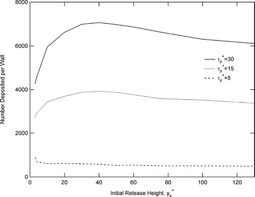
In order to more definitively determine the relative effects of the secondary flows and turbophoresis on deposition, we employ the results from the case B simulations, which involve a release of particles at specified heights above the duct walls. displays the number of particles that deposited per wall during the entire simulation (675 time wall units) as a function of the initial release height and for three different values of particle inertia (τ p + = 5, 15, and 30). The data corresponding to τ p + = 15 and 30 exhibit a peak in the number deposited at an initial release height of y 0 + = 40. This is not an artifact of the finite simulation time, because particles became distributed throughout the duct cross section well before the end of the simulation, as evidenced by the data corresponding to τ p + = 5 which stays relatively flat with y 0 +. Note that the maximum deposition for the particles having τ p + = 5 occurs at the lowest release height of y 0 + = 3. This may be explained in terms of a free-flight mechanism. Initially, each particle is given a velocity equal to that of the fluid at its location. For free-flight to the wall to occur, a particle must be within its stopping distance to the wall, which for a particle having τ p + = 5 and an initial velocity equal to 1 (normalized with u τ) is y stop + = 5.
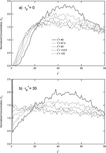
Certainly the free-flight mechanism cannot solely explain the maxima observed at y 0 + = 40 for the higher inertia particles. Rather, the spatial distribution initially centered at y 0 + = 40 gradually broadens, while at the same time becoming skewed towards wall due to turbophoresis. This behavior is evident from , which displays the concentration, C N , normalized with the average concentration in the duct, as a function of height above the wall for particles initially released at y 0 + = 50 at four different snapshots during the simulation between t + = 45 and t + = 135. The top plot () corresponds to passive tracers, and the bottom () corresponds to finite inertia particles (τ p + = 30). For passive tracers, the maximum in the distribution remains close to y + = 50, whereas for the finite inertia particles, the maximum gradually approaches the wall between t + = 45 and t + = 135.
FIG. 6 Plots of instantaneous normalized particle concentration at five times during the simulation for a) passive tracers and b) finite-inertia particles. In both cases, the initial release height is y o + = 50, and the concentration, C N , is normalized with the average concentration throughout the duct cross section.
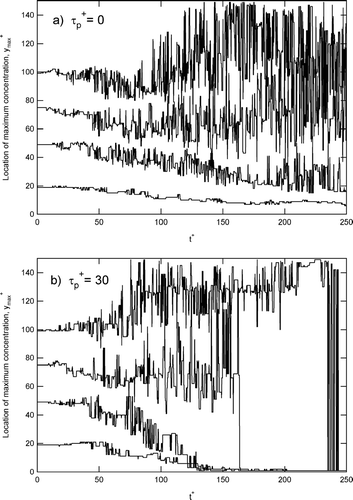
In order to better visualize this effect for different initial release heights, we have tracked the maximum in the spatial distribution as a function time. These data are presented in for passive tracers, and in for particles having τ p + = 30. Each plotted data set corresponds to a different initial release height, y 0 +, which may be determined by the value at t + = 0. For passive tracers, the location of the maximum in the distribution stays relatively constant, until it begins to change chaotically for each subsequent time step, indicating that the particles are uniformly distributed throughout the duct cross section. As expected, the particles become uniformly distributed sooner for particles released farther from the duct walls. By contrast, the maximum in the spatial distribution of particles having τ p + = 30 gradually approaches the wall between t + = 45 and t + = 135 for y 0 + = 20 and y 0 + = 50. This behavior occurs for release heights up to y 0 + = 60, beyond which particles become more uniformly distributed until preferential concentration of the particles in the sublayer quickly shifts the location of the maximum to the near-wall region.
FIG. 7 Location of the maximum concentration as a function of time for y o + = 20, 50, 75, and 100 for a) τ p + = 0, b) τ p + = 30.
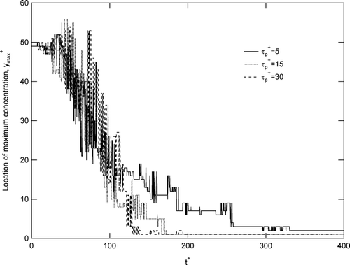
The efficient transport of finite-inertia particles towards the duct wall for initial release heights lower than y 0 + = 60 may be attributed to either turbophoresis or transport by the lateral mean flow. In order to distinguish between these two modes of transport, we note that, for the values of particle inertia considered here, turbophoresis is inertia-dependent, whereas transport by the mean flow is not. , which tracks the location of the maximum as a function of time for three values of particle inertia, suggests that the particles migrate towards the wall embedded within the mean flow. However, unlike passive tracers, which are carried to the wall and then back to the core, finite-inertia particles tend to deposit or accumulate near the wall at an inertia-dependent rate. This inertia-dependent effect is evident from beyond roughly t + = 100.
FIG. 8 Location of the maximum concentration as a function of time for τ p + = 5, 15, and 30. In each case, the initial release height was y o + = 50.
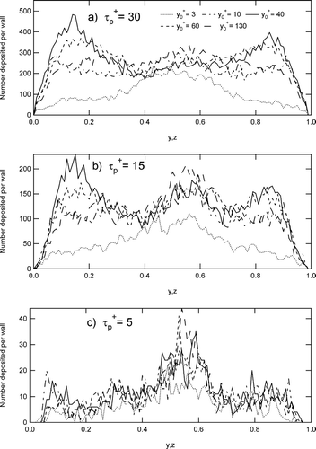
One would expect the effect of the secondary flows to be most prominent for the deposition of particles some distance from the center of the duct wall. For example, the deposition patterns shown in exhibit the off-center deposition peaks located a distance of 0.1 from the corners (i.e., at y,z = 0.1 or 0.9). In light of the discussion in this section, one would expect maximum off-center deposition for particles that are initially released near y 0 + = 40, and a smaller effect of initial release height on deposition close to the center of the wall. This behavior is evident from the deposition patterns plotted for varying initial release heights displayed in for τ p + = 30 (), τ p + = 15 (), and τ p + = 5 (). That figure demonstrates that initial release height only affects the deposition rate for higher inertia particles (τ p + ≥ 15), and only close to the corners. The deposition rate of lower inertia particles is always greater towards the center of the wall, and appears relatively insensitive to y 0 + throughout.
DISCUSSION
From the computations presented here, one may conclude the following about the mechanism governing the deposition of particles in a square duct. The secondary flows carry particles from the duct core to the corners. Higher-inertia particles (τ p + > 10) deposit efficiently close to the corners, gaining momentum towards the wall from the turbulent fluctuations in the outer region of the boundary layer. Lower-inertia particles have smaller stop distances, and thus tend not to deposit close to the corners. Rather, they are carried by the mean secondary flow towards the center of the wall, and then back into the duct core. The mean secondary flow velocity has been previously shown (CitationGavrilakis 1992) to be higher along the walls than along the diagonals of the duct. Thus particles that do not deposit immediately in the corners may be efficiently carried away from the corners and towards the wall midpoints. Since there appears to be a critical value of roughly τ p + = 10, above which corner deposition is more efficient, it is interesting to note that this corresponds to particles that have a stop distance equal to the size of the viscous sublayer, assuming an initial velocity equal to u τ.
The efficient corner deposition of particles having τ p + = 15 and 30 from an initial height of y 0 + = 40 and the corresponding insensitivity to initial height of the deposition along the center of the wall suggest unique transient flow structures in the corner that are conducive to deposition. These are likely related to the high mean streamwise vorticity gradients present in the corners (CitationGavrilakis 1992).
The extension of these deposition mechanisms to higher Reynolds number flows, such as those encountered in ventilation ducts, requires that the relative contributions of turbophoresis and the mean secondary flows to particle transport remain similar. One might imagine that increasing the Reynolds number should not significantly affect the deposition rates, since the turbulence variations close to the wall would not be significantly altered (CitationYoung and Leeming 1997). However, additional work is needed to definitively address the effect of Reynolds number on the secondary flows, turbophoresis, and thus deposition.
CONCLUSIONS
Direct numerical simulation of a turbulent flow through a square duct coupled with Lagrangian particle tracking was used to investigate the mechanisms by which particles deposit to the duct walls. The non-uniform deposition patterns along the walls of the duct indicate that the secondary flows play an important role in the deposition process. Our computations suggest that they tend to transport particles from the core of the duct towards the corners of the duct cross section and that they tend to preferentially recirculate lower inertia particles back into the duct core. Consequently, the secondary flows cause an increase in deposition closer to the corners for the higher-inertia particles and a decrease for the lower-inertia particles. This results in a greater sensitivity of the deposition velocity to particle inertia, compared to a circular pipe. The deposition rate along the wall close to the centerline appears less affected by the presence of the secondary flows.
Acknowledgments
The DNS computations were performed at the Texas A&M Supercomputing Facility and on the NSF Terascale Computing System at the Pittsburgh Supercomputing Center under NSF-NPACI grant no. CTS030005P. Partial financial support from the Comprehensive Test Ban Treaty Organization (CTBTO) through the Lovelace Respiratory Research Institute under contract no. JK020160 is also gratefully acknowledged.
REFERENCES
- Brooke , J. W. , Hanratty , T. J. and McLaughlin , J. B. 1994 . Free-Flight Mixing and Deposition of Aerosols . Phys. Fluids , 6 : 3404 – 3415 . [CSA]
- Botto , L. , Narayanan , C. , Fulgosi , M. and Lakehal , D. 2005 . Effect of Near-Wall Turbulence Enhancement on the Mechanisms of Particle Deposition . Int. J. Multiphase Flow , 31 : 940 – 956 . [CROSSREF] [CSA]
- Davies , C. N. 1966 . “ Deposition from Moving Aerosols ” . In Aerosol Science , Edited by: Davies , C. N. 393 – 446 . New York : Academic Press .
- Fan , F. and Ahmadi , G. 1993 . A sublayer Model for Turbulent Deposition of Particles in Vertical Ducts with Smooth and Rough Surfaces . J. Aerosol Sci. , 24 : 45 – 64 . [CROSSREF] [CSA]
- Friedlander , S. K. and Johnstone , H. F. 1957 . Deposition of Suspended Particles from Turbulent Gas Streams . Ind. Eng. Chem. , 49 : 1151 – 1156 . [CROSSREF] [CSA]
- Gavrilakis , S. 1992 . Numerical Simulation of Low-Reynolds-Number Turbulent Flow Through a Straight Square Duct . J. Fluid Mech. , 244 : 101 – 129 . [CROSSREF] [CSA]
- Huser , A. and Biringen , S. 1993 . Direct Numerical Simulation of Turbulent Flow in a Square Duct . J. Fluid Mech. , 257 : 65 – 95 . [CROSSREF] [CSA]
- Kajishima , T. and Miyake , Y. 1992 . A Discussion on Eddy Viscosity Models on the Basis of the Large Eddy Simulation of Turbulent Flow in a Square Duct . Comput. Fluids , 21 : 151 – 161 . [CROSSREF] [CSA]
- Liu , B. Y. H. and Agarwal , J. K. 1974 . Experimental Observation of Aerosol Deposition in Turbulent Flow . J. Aerosol Sci. , 5 : 145 – 155 . [CROSSREF] [CSA]
- Madabhushi , R. K. and Vanka , S. P. 1991 . Large Eddy Simulation of Turbulence-Driven Secondary Flows in a Square Duct . Phys. Fluids , 3 : 2734 – 2745 . [CROSSREF] [CSA]
- Marchioli , C. , Guisti , A. , Salvetti , M. V. and Soldati , A. 2003 . Direct Numerical Simulation of Particle Wall Transfer and Deposition in Upward Turbulent Pipe Flow . Int. J. Multiphase Flow , 29 : 1017 – 1038 . [CROSSREF] [CSA]
- McLaughlin , J. B. 1989 . Aerosol Particle Deposition in Numerically Simulated Channel Flow . Phys. Fluids A , 1 : 1211 – 1224 . [CROSSREF] [CSA]
- Rovelstad , A. L. , Handler , R. A. and Bernard , P. S. 1994 . The Effect of Interpolation Errors on the Lagrangian Analysis of Simulated Turbulent Channel Flow . J. Comput. Phys. , 110 : 190 – 195 . [CROSSREF] [CSA]
- Saffman , P. G. 1965 . The Lift on a Small Sphere in a Slow Shear Flow . J. Fluid Mech. , 22 : 385 – 400 . [CROSSREF] [CSA]
- Sharma , G. and Phares , D. J. 2006 . Turbulent Transport of Particles in a Straight Square Duct . Int. J. Multiphase Flow , 32 : 823 – 837 . [CROSSREF] [CSA]
- Sippola , M. R. and Nazaroff , W. W. 2003 . Modeling Particle Loss in Ventilation Ducts . Atmos. Environ. , 37 : 5597 – 5609 . [CROSSREF] [CSA]
- Vazquez , M. S. and Metais , O. 2002 . Large-Eddy Simulation of the Turbulent Flow Though a Heated Square Duct . J. Fluid Mech. , 453 : 201 – 238 . [CROSSREF] [CSA]
- Wang , Q. , Squires , K. D. , Chen , M. and McLaughlin , J. B. 1997 . On the Role of Lift Force in Turbulence Simulations of Particle Deposition . Int. J. Multiphase Flow , 23 : 749 – 763 . [CROSSREF] [CSA]
- Young , J. and Leeming , A. 1997 . A theory of Particle Deposition in Turbulent Pipe Flow . J. Fluid Mech. , 340 : 129 – 159 . [CROSSREF] [CSA]
