Abstract
This study designed and calibrated a novel three-stage personal dust sampler for sampling inhalable, thoracic, and respirable dust fractions simultaneously. The sampler has an annular inlet as the first stage for inhalable dust sampling, two impactors in the second and third stages to classify thoracic and respirable dusts, respectively, and a final filter. Laboratory calibration tests using monodisperse liquid and solid particles showed that with 100 ppi (pores per inch) PUF (porous polyurethane foam) substrates and at the flow rate of 3.2 L/min, the sampling efficiency curves of both impactor stages matched with the ISO/CEN/ACGIH thoracic and respirable sampling criteria, respectively. The sampler also agreed with the inhalable criterion for particles smaller than 17 μ m while the deviation increases with increasing particle diameter with a maximum of 28% for 27 μ m particles. It was also found that collection efficiency curve for solid particles was similar to that of liquid particles, indicating that there was no solid particle bounce from the PUF substrates for both impactors.
This study also compared inhalable, thoracic, and respirable dust concentrations measured by the present three-stage personal dust samplers with those of the Respicon samplers at three different workplaces. Without using a correction factor of 1.5 for the extrathoracic dusts of the Respicon, field results showed that the present three-stage sampler measured three dust fractions comparable to those of the Respicon samplers. The inhalable dust concentrations of the two samplers differed within 5% while the thoracic and respirable concentration differed by less than 22%.
INTRODUCTION
Particle size-selective sampling in the workplaces is performed to measure the worker's exposure to particles at different regions of the human respiratory system, and to find out if the Threshold Limit Values (TLVs) are exceeded. The ISO (International Organization for Standardization)/CEN (Comité Européen de Normalisation)/ACGIH (American Conference of Government Industrial Hygienists) proposed three criteria for dust sampling, including the inhalable fraction (IF, the efficiency of entry of particles into the nose or mouth), the thoracic fraction (TF, the fraction of particles that will pass beyond the larynx and reach the thorax or chest) and the respirable fraction (RF, the fraction of particles which can reach the gas exchange region of the lung). The size ranges of the IF, TF, and RF are defined in the range from 0 to 100 μ m (cutoff diameter = 80–100 μ m), 0 to 30 μ m (cutoff diameter = 10 μ m) and 0 to 10 μ m (cutoff diameter = 4 μ m), respectively.
Many dust samplers were developed for matching the criterion of one of the dust fractions only. Samplers such as the 10 mm nylon cyclone (CitationSeltzer et al. 1971), the SKC Aluminum cyclone (SKC Inc., Eighty Four, PA, USA), the IOSH cyclone (CitationTsai et al. 1997), and the single nozzle impactor with polyurethane foam substrate (CitationHuang et al. 2005) were developed for respirable dust sampling. Among them, the IOSH cyclone was designed with a larger inner diameter of 18 mm than the 10 mm nylon cyclone to reduce the effect of deposited particles in the cyclone on particle collection efficiency. The GK2.69 cyclone (CitationKenny and Gussman 1997; CitationMaynard 1999) and IOM thoracic samplers (CitationAitken et al. 1995) are used for thoracic dust sampling, in which the latter was designed to separate out the extrathoracic fraction using a foam pre-separator, allowing the thoracic fraction to be collected onto a 37 mm diameter after filter. For inhalable dust sampling, the IOM sampler (SKC Inc., Eighty Four, PA, USA) designed by CitationMark and Vincent (1986) and the Button sampler (SKC Inc., Eighty Four, PA, USA) designed by CitationKalatoor et al. (1995) are widely adopted.
However, all of the above samplers can sample one dust fraction only. There are few samplers that have been developed to measure the inhalable, thoracic, and respirable fractions simultaneously. TSI Respicon originally developed by CitationDunkhorst et al. (1995) and commercialized by TSI (Model 8522, TSI Inc., St. Paul, MN, USA) and Helmut Hund GmbH (Wetzlar, Germany) is one of them. This sampler has two virtual impactors in the first and second stages with cutoffs at 4 and 10 μ m, respectively, and an after filter in the third stage to collect particles larger than 10 μ m. The operating total flow rate of the Respicon is recommended to be 3.11 ± 2% L/min. For the internal flow rates, it is 2.66 ± 3% L/min through stage 1, 0.33 ± 5% L/min through stage 2, and 0.11 ± 5% L/min through stage 3. The aerosols collected on the stage 1 filter represent the respirable dust, those collected on the stage 1 plus stage 2 represent the thoracic dust, and the sum of all three stages represents the inhalable dust. In order to match the inhalable criterion, TSI reported that a correction factor of 1.5 has to be used for the mass of the third stage sample (extrathoracic dust concentration, C exth ) as
CitationLi et al. (2000) tested six inhalable dust samplers in a small wind tunnel at wind speeds of 0.55 and 1.1 m/s using monodisperse solid particles with aerodynamic diameter ranging from 5 to 68 μ m. The six samplers were the Respicon, IOM, a seven-hole, a conical inhalable sampler, a prototype button sampler and a closed-face 37-mm cassette. They found that with the annular slit inlet of the Respicon, the effect of orientations on collection efficiency did not occur. The sampler was found to match with the definition curve of the inhalable fraction quite accurately without applying the factor of 1.5. According to these results, TSI recommended that Respicon users discontinue applying the correction factor of 1.5 when calculating the inhalable fraction (CitationTSI 2001). However, under calm wind condition, the Respicon showed sampling deficiency with increasing diameter for particles greater than 6.0 μ m in CitationFeather and Chen (2003) (wind speed < 0.015 m/sec), and for particles greater than 30 μ m in CitationKoch et al. (1999) (wind speed < 0.2 m/sec).
Traditionally, cyclones were used for respirable or thoracic dusts sampling such as the SKC aluminum cyclone and the GK 2.69 cyclone (BGI Inc., Waltham, Mass.), respectively. Their penetration curves are less sharp than those of impactors and can match with the respirable criterion. Cyclones are usually designed for only one cut size while impactors are easily designed as a cascade impactor for size-classified particle sampling (CitationHuang et al. 2005). CitationMarple (1978) designed a single stage impactor with multiple round nozzles of different sizes. They found that the impactor penetration curve could approximate the respirable curve of ACGIH when three different nozzle sizes were used in the impactor design. CitationKavouras and Koutrakis (2001) used porous polyurethane foams (PUFs) as the impaction substrates in the inertial impactors. They found the use of PUFs resulted in significant changes in the collection efficiency curves, which were shifted to the left of the curves of the flat-plate impactors. The curves were less sharp than those of the flat-plate impactors. CitationHuang et al. (2005) further demonstrated that using the PUF (Foamex Inc., Pennsylvania, USA) as the impaction substrate, a single round nozzle impactor could be used for respirable dust sampling. As an extension of this work on the single stage impactor, it is therefore desirable to design a cascade impactor which uses PUF as impaction substrates to classify the three dust fractions simultaneously.
In this study, a three-stage impactor was designed and tested for sampling three dust fractions simultaneously. Monodisperse liquid and solid particles were used to evaluate the sampler in a calm air chamber in the laboratory. Field sampling was conducted in three different workplaces to compare the three dust concentrations of the three-stage sampler and the Respicon. In addition, the IOSH cyclone was used for the comparison of respirable concentration with that of the Respicon and the present sampler.
The Novel Three-Stage Sampler
The novel three-stage sampler uses a fixed sampling flow rate of 3.2 L/min throughout the three stages. As shown in , the sampler has an annular inlet as the first stage, a thoracic impactor as the second stage and a respirable impactor as the third stage followed by an after filter. The outer diameter and total weight of the sampler are 5.0 cm and 183 g, respectively.
FIG. 1 Schematic diagram of the novel personal 3-stage dust sampler. (a) Top view of the inlet top disc. (b) Schematic diagram of the present 3-stage sampler, PUF1, PUF2, and PUF3.
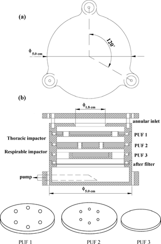
shows the top view of the top disc of the annular inlet which has a diameter of 5.0 cm. The disc has three ears used for the purpose of assembling the sampler. In the downstream of the annular inlet, an impaction substrate (PUF1) following a large round nozzle of 1.8 cm in diameter is used to collect part of extrathoracic particles. Inlet of this annular form was found to have high sampling efficiency up to 15 μ m and 15 km/hr windspeed for an atmospheric PM-10 sampling inlet (CitationLiu and Pui 1981). also shows the schematic diagram of PUF1, PUF2 and PUF3, in which the six holes in each of PUF1 and PUF2 are used to accommodate the nozzles of the thoracic and respirable impactors, respectively.
The thoracic impactor has a cutoff aerodynamic diameter of 10 μ m and the second PUF (PUF2) as the impaction substrate. The respirable impactor has a cutoff aerodynamic diameter of 4 μ m and the third PUF (PUF3) as the substrate. The after filter (AF) was used to collect respirable particles. The impactors of the sampler were designed with the square root of the cutoff Stokes number,√Stk 50, of 0.39, which was determined according to CitationHuang et al. (2005). Stk 50 is defined as
Particles collected on the AF represent the respirable dust. The sum of particles collected on the PUF3 and the AF represents the thoracic dust while the sum of all three PUFs and the AF represents the inhalable dust. That is, the mass concentration of the respirable (C R ), thoracic (C T ), and inhalable (C I ) dusts of the present three-stage sampler can be calculated as
METHODS
Calibration in the Laboratory
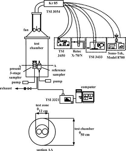
In this study, both monodisperse liquid oleic acid (OA) particles tagged with uranine dye and standard fluorescent polymer microspheres (Duke Scientific, Palo Alto, CA) between 1.8–20.2 and 1.9–27.7 μ m, respectively, were used to calibrate the present three-stage sampler at a calm air chamber (wind speed < 0.01 m/sec). As shown in , the chamber has an inner diameter of 50 cm and a small fan was used for particle mixing. Before calibrating the three-stage sampler, the concentration uniformity of the generated particles in the chamber was examined first by five reference samplers, each consisted of a vertical tube and a filter holder designed based on the criterion of CitationAgarwal and Liu (1980). The five reference samplers were located uniformly in the central part of the chamber to cover the test zone, which is a circular region of 12 cm in diameter. OA particles of 20.2 μ m and fluorescent polymer microspheres at 27 μ m in aerodynamic diameter were generated by a vibrating orifice monodisperse aerosol generator (VOMAG, TSI Model 3450) and a small scale powder disperser (TSI Model 3433), respectively, to conduct the uniformity test. The sampling flow rate was 2 L/min through each sampler and the sampling time for OA particles and fluorescent microspheres was 0.5 and 5 hours, respectively. After sampling, the glass fiber filters were soaked in 0.001 N NaOH (for OA particles) or xylene (for fluorescent microspheres) (CitationGlenny et al. 1993) and were ultra-sonicated for 30 minutes, allowing the fluorescence material to dissolve in the solutions. The uranine mass of particles collected on the filters was measured by a fluorometer (Turner Designs Model 10-AU-005, Cincinnati, OH, USA). Results showed that the sampled particle concentrations of the five samplers differed within 10%. That is, the chamber is uniform across the test zone of the chamber.
Calibration of the three-stage sampler was conducted inside the test zone in which a reference sampler was collocated with a three-stage sampler as shown in . An Aerodynamic Particle Sizer (APS, TSI Model 3321) was used for checking the size of particles produced by the VOMAG. OA particles from 1.8–20.2 μ m in aerodynamic diameter were generated by the VOMAG; ammonium sulfate ((NH4)2SO4) particles from 0.8-7.2 were generated by an atomizer (Sono-Tek 8700, Sono-Tek Inc., N.Y.); fluorescent microspheres from 1.9–5 μ m and 6.2–27.7 μ m in aerodynamic diameter were generated by another atomizer (Retec X-70/N, Cavitron Corp., Portland, OR) and a powder disperser, respectively. After sampling, particle uranine mass on the three PUFs and the after filter of the three-stage sampler was determined in the same way as that conducted in the chamber uniformity test. To determine particle wall loss, cotton swabs were used to recover deposited particles at the inner surfaces, which were also dissolved in 0.001 N NaOH (for OA particles) or xylene (for fluorescent microspheres) for further determination of fluorescence concentration. It was found that most particle loss occurred at the bottom of the annular slot mainly due to gravitational settling, while wall loss was negligible at other parts of the sampler (< 0.5% for all sizes particles tested).
The RF, TF, and IF of the present three-stage sampler are related to the aspiration efficiencies, η asp , which is defined as
The theoretical transmission efficiency, η trans, theo , due to gravitational settling was also calculated in the present study, which is equal to 1 minus theoretical settling efficiency, η s, theo . As a particle enters the annular inlet of the present sampler, it starts to settle toward the bottom plate of the annular inlet with its terminal settling velocity, V ts (m/s). η s, theo can be calculated as
Combining Equations [11–13], the following equation for dh can be obtained:
The RF, TF, and IF of the present three-stage sampler were determined experimentally as
Field Sampling
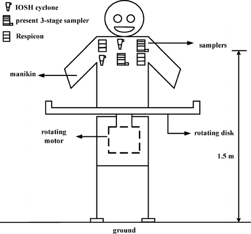
In field sampling study, two three-stage samplers, two IOSH cyclones and two Respicons were mounted on a life-sized rotating mannequin simultaneously as shown in to conduct the tests in three factories, including a lead powder, a lead-acid battery, and a casting factory. The height of the samplers was 1.5 m from the ground. The sampling locations were near a ball mill in the lead powder factory, the plate cutting area of the lead-acid battery plant, and the pouring area of the casting factory. The wind speed in all three sampling sites was below 0.1 m/s. To ensure uniform particle concentration, the mannequin was rotated at the speed of 1 turn per 10 minutes. Sampling lasted for 4–6 hours and at least six effective samples were obtained in each workplace. Equations [4–6] were used to determine the three dust concentrations measured by the three-stage sampler.
It was found that the environmental condition in the weighing room and the condition chamber (24-h conditioning before and after sampling) must be controlled carefully to obtain accurate weighing data for PUFs since they absorb water vapor readily. In this study, temperature was controlled between 22 ± 0.4°C, and relative humidity (RH) was kept at 35 ± 3% in the weighing room and condition chamber. The precision of weighing was determined to be 5 μ g by repeated weighing for at least 5 times.
RESULTS AND DISCUSSION
Laboratory Test
shows the Inhalable fraction (or inlet efficiency) of the present three-stage sampler for particles from 0.8 to 27 μ m. The current sampler agrees with the inhalable criterion (solid curve) very well for particles from 0.8 to 17 μ m with a maximum deviation of 8%. The deviation increases with increasing particle diameter with a maximum of 28% for 27 μ m particles. This difference is mainly caused by low transmission efficiency due to gravitational settling in the inlet. Similar inhalable fraction for liquid and solid particles indicates there is no solid particle bounce in the present sampler.
FIG. 4 Comparison of the inhalable fraction between the experimental data of the 3-stage sampler and the criteria.
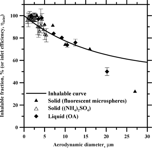
Under calm wind condition, the inhalable fraction of the present sampler shows a similar decreasing trend with increasing diameter as that of the Respicon in CitationFeather and Chen (2003) (wind speed < 0.015 m/sec), and CitationKoch et al. (1999) (wind speed < 0.2 m/sec).
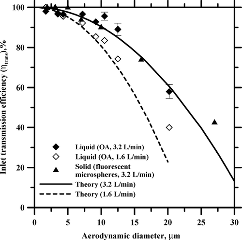
The experimental transmission efficiency is shown in , together with the theoretical transmission efficiency. Good agreement in for both flow rates of 1.6 and 3.2 L/min indicates the deposition efficiency of the annular inlet can be predicted theoretically. According to Equation [Equation15], η trans can be increased when the flow rate or R 2 (inner radius of the bottom plate) is increased or R 1 (the radius of the top plate) is decreased. That is, Equation [Equation15] can be used to design a better annular inlet which can increase the η trans as well as the IF for large particles to match with the inhalable, curve better in the future.
FIG. 5 Comparison of the theoretical and experimental inlet transmission efficiencies of the 3-stage sampler.
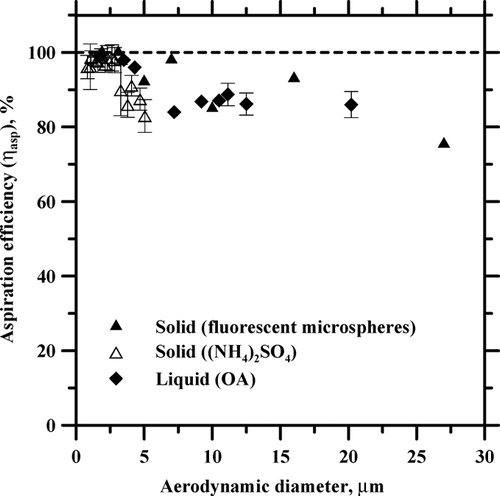
The experimental aspiration efficiency, η asp , versus aerodynamic diameter is calculated from Equation [Equation7] and shown in . It is seen the η asp is close to 100% for particles smaller than 3 μ m while η asp is about 80–90% for particles greater than 3 μ m. There are no significant differences for η asp between liquid and solid particles.
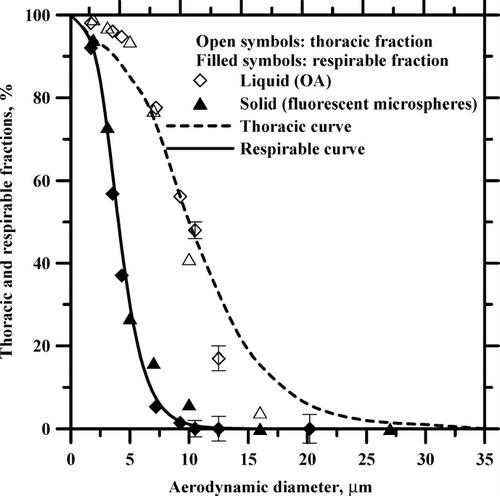
shows the comparison of the respirable and thoracic fractions between the experimental data of the three-stage sampler and the criteria of the ISO/CEN/ACGIH (shown as curves). The experimental respirable and thoracic dust fractions were calculated by Equations [Equation16] and [Equation17], respectively. For thoracic dust, the present sampler oversamples slightly with a maximum deviation of 8% for particles smaller than 5 μ m while it undersamples the dust with a maximum deviation of 10% when particles are larger than 10 μ m. The thoracic cutoff size of the sampler is 9.6 μ m in aerodynamic diameter, which is close to criterion value of 10 μ m. For respirable dust, the present data almost fall on the respirable curve with the cutoff aerodynamic diameter of 4 μ m. In addition, there are no significant differences of sampling efficiencies between solid and liquid particles. That is, the present sampler using PUFs as the impaction substrates matches both thoracic and respirable criteria simultaneously very well.
Field Sampling
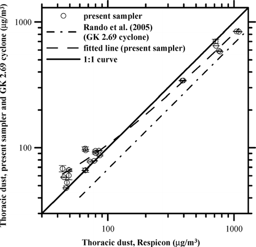
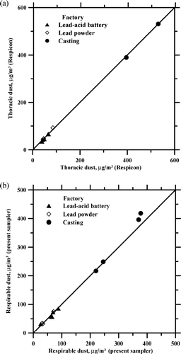
Before comparing particle concentrations between the Respicon, three-stage sampler and the IOSH cyclone, two collocated identical samplers were compared first to show the precision of the tests. shows the comparison of the thoracic dust concentrations sampled by the two collocated Respicons. It is seen all data at the three workplaces are almost fall on the 1:1 line. Similar results are observed in which shows the respirable dust concentrations sampled by two collocated three-stage samplers. Concentrations of other dust fractions for any of two identical samplers show similar agreement. Furthermore, linear regression analysis of the data for all three workplaces showed no significant difference (p > 0.05) between the two collocated samplers for all three dusts. That is, the precision of the present field comparison study is very good.
FIG. 8 Comparison of two collocated samplers: (a) the thoracic dust concentrations sampled by the Respicon, (b) the respirable dust concentrations sampled by the present 3-stage sampler.
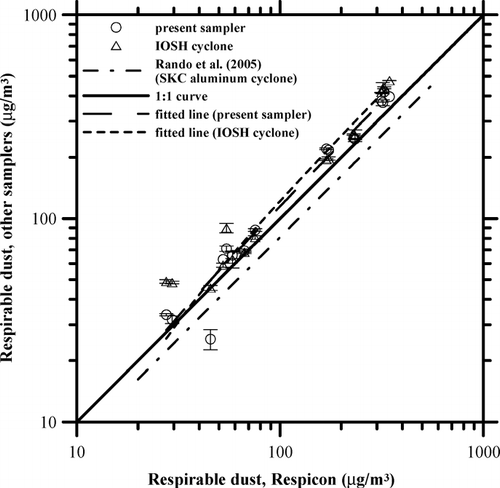
shows the comparison of respirable dust concentrations sampled by the IOSH cyclone, the present three-stage sampler and the Respicon. The three-stage sampler and IOSH cyclone collected similar respirable dust concentrations with less than 10 % difference, but they were 20 and 31% higher than the Respicon, respectively. For comparison, the study of CitationRando et al. (2005) showed the SKC cyclone had 19% lower respirable dust concentration of the Respicon.
FIG. 9 Comparison of the respirable dust concentration between the 3-stage sampler, the IOSH cyclone, and the Respicon.
The comparison of the thoracic dust concentrations between the present three-stage sampler and the Respicon is shown in . It shows the three-stage sampler sampled lower thoracic concentrations than the Respicon with a difference of about 22%. For comparison, the study of CitationRando et al. (2005) showed the GK 2.69 cyclone sampled 32% lower thoracic dust than the Respicon.
While the differences between the reference samplers and the Respicon in CitationRando et al. (2005) need further explanation, the reason why the present sampler undersampled the thoracic dust by 22% compared to the Respicon maybe due to higher thoracic sampling efficiency of the Respicon as shown in of CitationFeather and Chen (2003) or of CitationKoch et al. (1999). Furthermore, shows the current sampler having a slightly sharper and lower thoracic sampling efficiency than the criterion curve may also lead to undersampling than Respicon.
The 20% oversampling of the respirable dust by the present sampler compared to that of the Respicon perhaps is due to slightly lower respirable sampling efficiency of the Respicon shown in of CitationKoch et al. (1999).
With and without applying the extrathoracic correction factor of 1.5 for the Respicon, the comparison of the inhalable dust concentration between the three-stage sampler and the Respicon is shown in . It is seen the three-stage sampler sampled slightly lower (within 5% difference) inhalable dust concentration than the uncorrected Respicon. However, the difference increased to about 24% compared to the corrected Respicon.
FIG. 11 Comparison of the inhalable dust concentration between the 3-stage sampler and the Respicon.
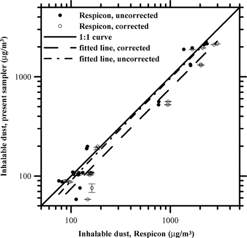
Although the present data show good agreement with the uncorrected Respicon for the inhalable dust under calm wind condition (< 0.1 m/sec), CitationKoch et al. (2002) found that an increase in sampling deficiency of the Respicon with increasing coarseness of the dust. It was suggested to correct the Respicon's extrathoracic dust by a factor of 1.8 to match with the CALTOOL reference sampler. Similarly, a correction factor of 1.5 for Respicon's extrathoracic dust was also found to be necessary for accurate inhalable sampling in CitationTatum et al. (2002) using CIS inhalable sampler as a reference sampler, and CitationRando et al. (2005) using IOM as a reference sampler in field studies. That is, the present three-stage sampler may also undersample inhalable fraction due to similar sampling deficiency for large particles. Further improvement can be made in the future to design a better inlet which reduces this discrepancy in the inhalable efficiency.
CONCLUSIONS
This study designed and calibrated a novel three-stage sampler using monodisperse liquid and solid particles in the laboratory at a calm air chamber. The sampler used a single fixed sampling flow rate of 3.2 L/min. Results showed that using PUFs as the substrates to design the two impactors in this sampler, it is able to match with the respirable and thoracic sampling criteria simultaneously. For the inhalable fraction, the present sampler showed a reasonable agreement with the inhalable convention, although an increase of sampling deficiency exists with increasing aerodynamic diameter for particles greater than 15 μ m. Similar inhalable, thoracic, and respirable fractions for liquid and solid particles indicated there was no solid particle bounce in the present sampler.
In field studies, two three-stage samplers, two IOSH cyclones, and two Respicons were mounted on a life-sized rotating mannequin simultaneously to conduct the sampling in three factories. The three-stage sampler was found to sample similar respirable dust concentration as the IOSH cyclone while it oversampled the respirable dust than the Respicon. The three-stage sampler sampled lower thoracic concentrations than the Respicon, which maybe due to higher thoracic sampling efficiency of the Respicon. For the inhalable dust, the present data showed good agreement with the uncorrected Respicon and the three-stage sampler. However, according to CitationFeather and Chen (2003), the present three-stage sampler may also undersample inhalable fraction due to similar deficiency of the inhalable curve for large particles. Further improvement can be made in the future to design a better inlet which reduces this discrepancy in the inhalable efficiency.
Acknowledgments
The authors would like to thank for the financial support of this project the Taiwan Institute of Occupational Safety and Health (IOSH94-A102).
REFERENCES
- Agarwal , J. K. and Liu , B. Y. H. 1980 . A Criterion for Accurate Aerosol Sampling in Calm Air . Am. Ind. Hyg. Assoc. J. , 41 : 191 – 197 .
- Aitken , R. J. and Donaldson , R. Development and Testing of Size-selective Personal Aerosol Sampling Devices based on Porous Foam Selectors . Abstract of Am. Ind. Hyg. Conf. May 1995 , Kansas, MO.
- Dunkhorst , W. , Lödding , H. and Koch , W. 1995 . A New Personal Monitor for Real-Time Measurement of the Inspirable, the Thoracic, and the Respirable Fraction of the Airborne Dust . J. Aerosol Sci. , 26 : S107 – S108 .
- Feather , G. A. and Chen , B. T. 2003 . Design and Use of a Setting Chamber for Sampler Evaluation under Calm-Air Conditions . Aerosol Sci. Technol. , 37 : 261 – 270 .
- Glenny , R. W. , Bernard , S. and Brinkley , M. 1993 . Validation of Fluorescent-Labeled Microspheres for Measurement of Regional Organ Perfusion . J. Applied Physiol. , 74 : 2585 – 2597 .
- Huang , C. H. , Chang , C. S. , Chang , S. H. , Tsai , C. J. , Shih , T. S. and Tang , D. T. 2005 . Use of Porous Foam as a Substrate of an Impactor for Respirable Aerosol Sampling . J. Aerosol Sci. , 36 : 1373 – 1386 .
- Kalatoor , S. , Grinshpun , S. A. , Willeke , K. and Baron , P. 1995 . New Aerosol Sampler with Low Wind Sensitivity and Good Filter Collection Uniformity . Atmos. Environ. , 29 : 1105 – 1112 .
- Kavouras , I. G. and Koutrakis , P. 2001 . Use of Polyurethane Foam as the Impaction Substrate/Collection Medium in Conventional Inertial Impactors . Aerosol Sci. Technol. , 34 : 46 – 56 .
- Kenny , L. C. and Gussman , R. A. 1997 . Characterization and Modeling of a Family of Cyclone Aerosol Preseparators . J. Aerosol Sci. , 28 : 677 – 688 .
- Koch , W. , Dunkhorst , W. L. and Lödding , H. 1999 . Design and Performance of a New Personal Aerosol Monitor . Aerosol Sci. Technol. , 31 : 231 – 246 .
- Koch , W. , Dunkhorst , W. , Lödding , H. , Thomassen , Y. , Skaugset , N. P. , Nikanov , A. and Vincent , J. 2002 . Evaluation of the Respicon as a Personal Inhalable Sampler in Industrial Environments . J. Environ. Monit. , 4 : 657 – 662 .
- Li , S. N. , Lundgren , D. A. and Rovell-Rixx , D. 2000 . Evaluation of Six Inhalable Aerosol Sampler . Am. Ind. Hyg. Assoc. J. , 61 : 506 – 516 .
- Liu , B. Y. H. and Pui , D. Y. H. 1981 . Aerosol Sampling Inlets and Inhalable Particles . Atmos. Environ. , 15 : 589 – 600 .
- Mark , D. and Vincent , J. H. 1986 . A New Personal Sampler for Airborne Total Dust in Workplaces . Ann. Occup. Hyg. , 30 : 89 – 102 .
- Marple , V. A. 1978 . Simulation of Respirable Penetration Characteristics by Inertial Impaction . J. Aerosol Sci. , 9 : 125 – 134 .
- Maynard , A. D. 1999 . Measurement of Aerosol Penetration through Six Personal Thoracic Samplers under Calm Air Conditions . J. Aerosol Sci. , 30 : 1227 – 1242 .
- Rando , R. , Poovey , H. , Mokadam , D. , Brisolara , J. and Glindmeyer , H. 2005 . Field Performance of Industrial Wood Processing Dust . J. Occup. Environ. Hyg. , 2 : 219 – 226 .
- Seltzer , D. F. , Bernaski , W. J. and Lynch , J. R. 1971 . Evaluation of Size-Selective Presamplers II. Efficiency of 10-mm Nylon Cyclone . Am. Ind. Hyg. Assoc. J. , 32 : 441 – 446 .
- Tsai , C. J. , Shih , T. S. and Sheu , R. N. 1997 . Characteristics of Lead Aerosols in Different Work Environments . Am. Ind. Hyg. Assoc. J. , 58 : 650 – 656 .
- Tatum , V. , Ray , A. E. and Rovell-Rixx , D. 2002 . Performance of the RespiCon (TM) Personal Aerosol Sampler in Forest Products Industry Workplaces . Am. Ind. Hyg. Assoc. J. , 63 : 311 – 316 .
- TSI . 2001 . St. Paul, MN, , USA : TSI Incorporated . http://www.tsi.com/documents/iti_078.pdf. Application Note ITI–078
- Witschger , O. , Fabries , J. F. and Gorner , P. 1997 . Particle Entry Efficiency of an Annular Slot Aerosol Sampler . J. Aerosol Sci. , 28 : S679 – S680 .
