Abstract
An In-line Virtual Impactor is presented, which has an application as a pre-separator for sampling inlets, where the device scalps large particles from the aerosol size distribution. Numerical simulation was the principal tool employed in the design process, with physical experiments used to verify computational predictions. Performance investigations were primarily carried out for a configuration that provides a nominal cutpoint particle size of 10 μ m aerodynamic diameter at an inlet flow of 111 L/min and a major flow exhaust of 100 L/min; however, the concept is scalable in terms of both flow rates and cutpoint sizes. An inverted dual cone configuration contained within a tube provides a characteristic circumferential slot of width 2.54 mm (0.100 inches) and a slot length of 239 mm (9.42 inches) at the critical zone. The upper cone causes the flow to accelerate to an average throat velocity of 3.15 m/s, while the lower cone directs the major flow toward the exit port and minimizes recirculation zones that could cause flow instabilities in the major flow region. The cutpoint Stokes number is 0.73; however, the cutpoint can be adjusted by changing the geometrical spacing between the acceleration nozzle exit plane and a flow divider. When the system is operated at the major exhaust flow rate of 100 L/min, the pressure drop is 45 Pa. Good agreement is obtained between numerically predicted and experimentally observed performance.
INTRODUCTION
A typical ambient aerosol sampling system includes a pre-separator that is designed to exclude large particles. In some applications, the performance of the pre-separator is intended to mimic the human respiratory system in excluding large particles from the thoracic region of the human lung system (CitationU.S. EPA 1987), while in other applications the pre-separator is used to strip particles that could confound analyses or could foul near-real time detection systems (CitationU.S. NRC 2005). In the context of near-real-time bioaerosol sampling, it is generally necessary to strip large pollen particles from the distribution if the aerosol is to be analyzed for fluorescent characteristics. The majority of large particle fractionators are inertial separation devices with the simplest being the classical inertial impactor. As an example, CitationMcFarland et al. (1984) developed an 1130 L/min all-weather PM-10 sampler multi-jet impactor inlet with a pre-separator that scalped large particles from the distribution prior to filter collection of particles with sizes ≤ 10 μ m aerodynamic diameter (AD). To minimize the problem of solid particle carryover in the pre-separator, the impaction surface was coated with a layer of high viscosity oil; however, the use of an oiled surface may not provide adequate large particle retention if the concentration of large particles is very high, as might be the case for some bioaerosol sampling scenarios. Particle trap impactors have been developed to reduce solid particle carryover by collecting the heavier particles in a cup or well instead of a flat plate (CitationBiswas and Flagan 1988; CitationKim et al. 2002).
Virtual impactors, which eliminate solid particle carryover, were developed as an alternative to classical impactors by CitationConner (1966). CitationPeterson (1975) and CitationDzubay and Stevens (1975) developed a dichotomous sampler, which operated on the principle of virtual impaction, to characterize ambient aerosols. Typically, the fractional efficiency curve of a virtual impactor is not as steep as that of a real impactor. Further, virtual impactor geometry is complex and its performance is critical to misalignments (CitationLoo and Cork 1988). Hence, most large particle fractionators used in inlets are still some form of a real impactor (CitationChow 1995); however, CitationRomay et al. (2002) have developed a circular jet virtual impactor pre-separator for bioaerosol sampling.
A circumferential-slot virtual impactor has certain inherent advantages relative to a circular jet virtual impactor in that a narrow slot can be easily fabricated and, provided the flow is stable, aerosol fractionation can be achieved with a low expenditure of pressure, CitationHaglund and McFarland (2004). Herein, we present the design, development, and characterization of a dual-cone circumferential-slot In-Line Virtual Impactor (IVI). Computational fluid dynamics techniques were used as an optimization tool to determine the appropriate combination of the critical geometrical parameters for the IVI.
PROTOTYPE DESCRIPTION
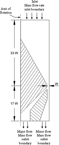
The dual cone IVI is shown schematically in and optimized design values are given in . For this rendition, a flow rate of 111 L/min of air is drawn into the IVI where it is accelerated in the nozzle formed by the gap between the waistline of the upper cone and the tube wall. As the accelerated jet issues from the nozzle, it is split into two parts (), where typically the major flow comprises 90% of the total flow and the minor flow comprises the remaining 10%. The major flow, which contains the aerosol fine fraction, is transported into the region between the inverted lower cone and the flow divider (). The lower cone is used to minimize the presence of recirculation zones in the major flow region and help ensure flow stability. The apex angles of the lower and upper cones are 90 and 60 degrees, respectively.
FIG. 1 Schematic diagram of the IVI. Nominal inlet air flow rate = 111 L/min and nominal major air flow rate = 100 L/min.
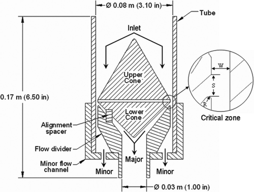
TABLE 1 Optimized design parameters for an IVI with a cutpoint of 10 μm AD and a major flow rate of 100 L/min
As the aerosol enters the critical zone, the larger particles are concentrated into the minor flow stream while the smaller aerosol particles, which are the particles of interest, are transported with the major flow. Because the particles in the minor flow are not of consequence when the IVI is operated as a pre-separator, they were not characterized in detail.
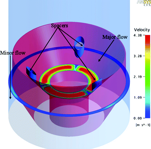
With reference to , alignment spacers are used to position the cones and to maintain the alignment of the cones with respect to the flow divider. The concentricity of the whole inner assembly with the outer casing is achieved by mating the flow divider concentrically with the minor flow channel. It will be demonstrated that the presence of three alignment spacers in the flow field does not significantly affect the performance of the IVI.
The IVI considered in this study is intended to be used as a pre-separator for bioaerosol concentrators and collectors that operate at flow rates of approximately 100 L/min. However, the device can be scaled to accommodate other flow rates and cutpoints.
NUMERICAL MODELING
CFX™ computational fluid dynamics software (Ver. 10.0, ANSYS, Canonsburg, PA) was used for modeling the performance of the IVI. CFX uses a coupled algebraic multi-grid solver that solves the hydrodynamic system of equations across all grid nodes. Initial geometric design and optimization studies were performed using 2D simulations; however, once the appropriate combination of parameters was determined, a 3D simulation was performed on the final design to ensure that the 2D predictions were representative of the fluid flow and particle physics in the IVI.
Geometry and Meshing
shows the geometry used in our simulations along with the boundary conditions. As the flow in the IVI can be considered to be axi-symmetric, a computational model representative of the IVI geometry was created by revolving the 2D profile by an angle of 3–5 degrees about the central axis, as suggested by CFX (CitationANSYS, 2005). A block structured body fitted mesh was generated over the entire domain using ICEMCFD™ (Ver. 10.0, ANSYS, Cannonsburg, PA).
Flow Field and Particle Tracking
Fluid and particle transport in the IVI was modeled with an Eulerian-Lagrangian framework. The bulk fluid (continuous phase) flow field was solved using the Eulerian approach and then the particle trajectories were calculated using Lagrangian tracking, with the assumption that the particles neither influence the flow field nor each other.
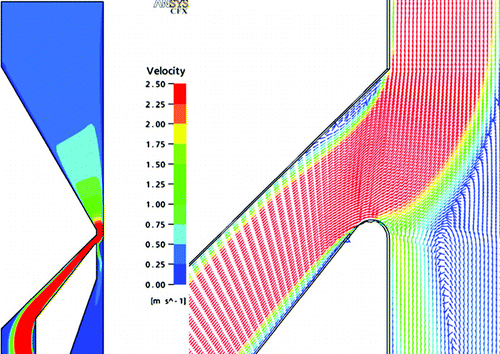
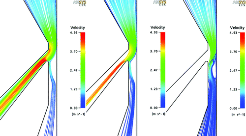
Two-dimensional simulation results of the air velocity contours in the IVI and velocity vectors in the critical zone are shown in . Velocity vectors in the minor flow region near the critical zone show the presence of a small recirculation bubble. Although it was not possible to completely eliminate the recirculation because the accelerated flow impinges into a relatively static void, it was minimized by adjusting the geometry.
FIG. 3 (a) Velocity contours in the flow field. (b) Velocity vectors in the critical zone where the flow separates into the major and minor flow streams.
Examples of particle trajectories computed for the 2D geometry are shown in . illustrates the behavior of 1 μ m AD aerosol particles, which are well below the cutpoint size of 10 μ m AD, and consequently follow the flow streamlines. In contrast, shows the trajectories of 25 μ m AD particles, which are well above the cutpoint size. They deviate from the flow streamlines in the critical zone and are inertially driven into the minor flow region. Trajectories of cutpoint size (10 μ m AD) particles are shown in where one-half of the particles enter the major flow region. Particles of this size are prone to impacting on the flow divider tip. However, by observing the particle trajectories and performing suitable modifications to the critical zone geometry it is possible to reduce the wall losses for the desired cutpoint size.
FIG. 4 Aerosol particle trajectories with color coding to show local velocities. (a) 1 μ m AD particles (b) 10 μ m AD particles (c) 25 μ m AD particles.
CitationHari et al. (2005) determined that tracking of 500 particles of each size was sufficient to ensure the independence of the obtained results from the number of particles. In this study, 1000 particles of each size were tracked to determine the fractionation characteristics of the IVI. Each particle was tracked from the injection point to its final destination (either a flow boundary or an internal wall). Particles that contacted an internal wall were considered to adhere to the wall. Penetration (major-flow transmission efficiency) for each size was obtained as the ratio of the number of particles in the major flow exit to the number of particles that were originally injected at the inlet boundary.
EXPERIMENTAL METHODOLOGY
The IVI was experimentally tested to characterize the major-flow transmission efficiency for a range of monodisperse liquid aerosol particle sizes from 4.0 to 15.0 μ m AD. Here, the major-flow transmission efficiency for a given particle size is defined as:
A schematic of the test setup is shown in . Aerosol, output from a vibrating orifice aerosol generator (VOAG, TSI Inc, Shoreview, MN), was passed through a flow duct where 111 L/min was extracted and drawn through the IVI. Aerosol sampling filters (47 mm, Type A/D glass fiber, Pall Corp., East Hills, NY) were used to collect particles from the major and minor flows. Reference samples, used to provide information for the denominator in Equation (Equation1) (inlet flow), were acquired by replacing the IVI in the setup of with a filter sampler. For a given set of experimental conditions, the reference filter and IVI were alternated to obtain at least three replicate samples.
FIG. 5 Setup used for experimental testing of IVI. Reference samples were obtained by replacing IVI with a filter operated at the same (111 L/min) flow rate.
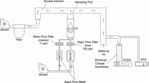
The aerosol particles were liquid droplets formed from atomization of an alcohol solution of oleic acid tagged with a fluorescent tracer (sodium fluorescein). The consistency of the aerosol being generated by the VOAG was monitored with an aerodynamic particle sizer (APS, TSI Inc, Shoreview, MN); however, the true size of the aerosol particles was determined microscopically as larger liquid droplets are known to distort when accelerated in the APS measurement section (CitationChen et al. 1990). Droplet size was calculated from the microscopically measured size adjusted for flattening of the droplets on a microscope slide according to the method described by CitationOlan-Figueroa et al. (1982), but with a flattening factor of 1.29 (CitationThien 2006) to take into account a different oil-phobic coating on the slides than that used by Olan-Figueroa.
Relative concentrations of aerosol in the test and reference samples were obtained by eluting the fluorescent dye from the test filters and analyzing the solutions fluorometrically (Turner Model FM109515, Quantech Barnstead International, Dubuque, IA). The filters were placed in a solution of 50% isopropyl alcohol and 50% distilled water (v/v) for at least four hours. For selected tests, wall losses were obtained by opening the IVI unit and extracting the deposited particles using a cotton swab moistened with isopropyl alcohol (CitationLoo and Jaklevic 1974).
RESULTS AND DISCUSSION
Transmission Efficiency
The major-flow transmission efficiency curves, T maj , obtained for the IVI operated at an inlet flow rate of 111 L/min and a major flow rate of 100 L/min, are shown in . Here, T maj is plotted as a function of Stokes number, Stk, where the latter is defined as:
FIG. 6 Major-flow transmission efficiency of IVI as a function of Stokes number. Effect of aspect ratio is shown for S/W values of 1.03, 1.35, and 1.75. Error bars on experimental results are ±1 standard deviation about the mean value.
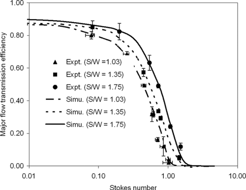
As shown in , the numerically predicted Stk 50 value of the IVI is 0.73 when the S/W ratio is 1.75. The results of the experimental tests verify this prediction. At an inlet flow rate of 111 L/min, the cutpoint particle aerodynamic diameter corresponding to these conditions is 10.0 μ m AD. The effect of the aspect ratio, S/W, was investigated both numerically and experimentally for S/W values of 1.03, 1.35, and 1.75. shows the cutpoint Stokes number to increase with increasing values of the S/W ratio. This could allow users some flexibility in adjusting the cutpoint for an application where the flow rate is specified.
The steepness of the transmission efficiency curve can be represented by the geometric standard deviation, s g , of the transmission efficiency values, which for discretized data is (CitationMcFarland et al. 1984):
For seven equally spaced intervals in the curve for S/W = 1.75, Equation (Equation3) yields a value of 1.51 for s g of the IVI. By comparison, CitationHaglund and McFarland (2004) presented minor flow transmission efficiency results for a slot virtual impactor, and the steepness of their curve, calculated from Equation (Equation3), was 2.1. As a reference, the value of s g would be unity for an ideal fractionator with a step-type fractionation curve, with increasing values of the steepness value associated with poorer fractionation characteristics.
TABLE 2 Comparison of steepness of IVI performance curve with those of selected real and virtual impactors
gives a summary of the steepness parameters for several real and virtual impactors. The steepness parameter of the linear slot virtual impactor of CitationDing et al. (2001) is 1.3. In comparison, the steepness parameters for the fractionation curves of the selected slot-type and round jet real impactors range from 1.1 to 1.3. This indicates the steepness parameter for the fractionation curve of the IVI is comparable to other virtual impactors; however, there are real impactors with lower values of the sharpness parameter.
Analyses were also conducted with the IVI scaled up to be operated at a major flow rate of 350 L/min, which results in an acceleration nozzle Reynolds number, Re, of 1730 as compared with the value of 545 for the major flow rate of 100 L/min. The Reynolds number is defined as:
Internal Wall Losses
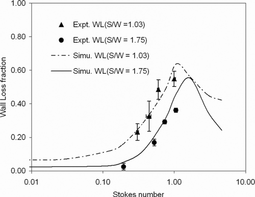
The transmission efficiency curves presented in take into account the internal wall losses. shows the experimental and predicted wall loss characteristics as a function of Stokes number. Here, wall losses for a given particle size are defined as ratio of the amount of aerosol deposited on the internal walls to the amount of material that entered the IVI. Losses at the cutpoint Stokes numbers are about 30%, and are predicted to peak at about 60%. It is important to note that these losses are primarily associated with the coarse particle fraction (minor flow). For example, the peak predicted losses occur at a particle size of 15 μ m AD; and, inspection of the trajectories of those particles show the wall impacts occur almost exclusively on the minor flow side of the flow divider. About 7% of the losses for S/W = 1.75 and 11% of the losses for S/W = 1.03 occur in a recirculation zone in the minor flow region downstream the flow divider tip (). The higher losses calculated for the smaller value of S/W, are due to greater impaction on the flow divider tip for the latter case.
FIG. 7 Internal wall loss characteristics of the IVI. The losses are essentially associated with the minor flow.
While the presence of wall losses tends to shift the cutpoint to lower Stokes number values, wall losses do not interfere with the operation of the IVI as a pre-separator, where only the fine fraction is of interest. Tests were conducted with aerosolized dry Arizona Fine Road Dust (ISO 12103–1, A2 Fine Test Dust, Powder Technology Inc., Burnsville, MN), which has a mass median diameter of about 10 μ m. A total of 145 mg of dust was sampled by the IVI over a period of 10 minutes and there was no buildup of dust in the critical zone. While the experiments with liquid droplets show wall losses of almost 30% near the cutpoint size, the dry dust exhibits solid particle carryover and is transported away from the critical zone.
The prediction of wall losses also partially explains why the cutpoint tends to shift to lower values while using smaller S/W ratios. In those cases, the particles that travel close to the tube wall get collected on the flow divider. With larger S/W ratios, these particles will be transported by the major flow.
Minor Flow Transmission Efficiency
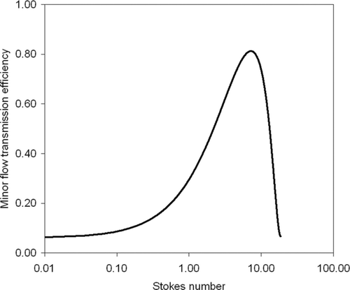
presents the numerically predicted minor flow transmission efficiency curve for S/W ratio of 1.75. The particle sizes represented by the Stokes numbers of the curve are as large as 50 μ m AD. A small percentage of the particles (7% for a size of 10 μ m AD) that enter the minor flow region get entrained in the recirculation region and are lost on the walls of the flow divider. Thus, if the IVI were to be considered for use as a coarse particle concentrator, it is likely that significant modifications to the critical zone geometry would be necessary to reduce the wall losses.
Pressure Loss
The experimentally measured pressure drop across the IVI inlet for the flow rate of 111 L/min and the S/W value of 1.75 was 45 Pa (0.18 inches of water). The corresponding numerical prediction is 46.1 Pa.
Effect of Alignment Spacers on Major Flow Transmission Efficiency
Particle deposition on the alignment spacers in the major flow channel was experimentally quantified to determine the impact of those losses on the performance of the device. For particles near the cutpoint size, only about 0.01% of the incoming aerosol was collected on the spacers. Deposition was also insignificant for particles beyond the cutpoint size as few of these particles are carried with the major flow. Thus it can be assumed that the presence of the alignment spacers does not significantly influence the transmission efficiency. The transmission efficiency curve generated using numerical simulation (presented in ) was obtained from a 3D model that included the spacers in the domain. illustrates the effect of the alignment spacers on the flow field in the annular plane located downstream of the spacers toward the major flow exit. It can be seen that the disturbances are localized and do not affect the global flow.
Effect of Minor Flow Ratio on Major Flow Transmission Efficiency
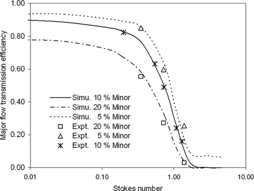
Virtual impactors typically operate at a 10% minor flow rate ratio, which was also selected as the nominal design flow split for the IVI. However, it is of interest to consider the performance changes that would result from the use of different flow ratios, as that might allow a user to either vary the cutpoints without the need to modify any hardware, or to accommodate prescribed flow rates that do not result in the 10% minor flow rate ratio. shows a comparison of major flow transmission efficiencies, for 5%, 10%, and 20% minor flow rate ratios. Results of both numerical simulations and physical experiments are shown in , with good agreement between the two approaches. With an increasing minor flow fraction, the cutpoint shifts to lower particle sizes because of an increase in the fraction of smaller particles inherently present in the minor flow. For particles with sizes larger than the cutpoint, the transmission efficiency curves tend to meld because inertial effects dominate. However, when just 5% of the flow is extracted through the minor flow, particles tend to lose their momentum and move back to the strong major flow. This results in heavy wall losses on the flow divider.
Comparison Between 2D and 3D Numerical Simulations
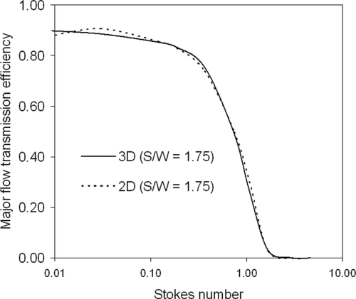
Initial optimization studies on the IVI design were performed on a 2D domain as shown in . It is important that the cutpoints predicted by 2D and 3D simulations match to justify the reliance placed on the 2D results. shows the comparison between the major flow transmission efficiency curves obtained using 2D and 3D simulation for S/W = 1.75. The cutpoint predicted by both simulations was 0.73. There are minor deviations, which are likely due to the manner in which a 2D axi-symmetric simulation is performed in CFX. When revolving the 2D profile along the axis, the profile is displaced by a small “δ” in order to avoid a singularity along the axis, while in 3D the entire domain is simulated and no such displacement is necessary.
SUMMARY AND CONCLUSIONS
A dual-cone in-line circumferential-slot virtual impactor (IVI) has been designed and tested using both numerical and experimental techniques. For the nominal design and operational conditions (S/W = 1.75 and Reynolds number = 545) the major flow cutpoint Stokes number is 0.73. In terms of particle size, when the major exhaust flow rate is 100 L/min in the prototype unit, the cutpoint size is 10 μ m AD. Experimental and numerical evaluations produced results that are in good agreement. Also, 2D simulations were initially used to design and optimize the geometry and the predicted cutpoints are in good agreement with the full domain 3D simulations.
The steepness of the major flow transmission efficiency curve, expressed as a geometric standard deviation, is 1.51, which is comparable to the values for other virtual impactors; however, it is less than some real impactors that have very sharp cuts (i.e., s g = 1.1).
An interesting feature of the IVI is that the nominal cutpoint could be somewhat varied by adjusting the alignment spacer height, which will change the S/W ratio. However, the principal control of the cutpoint is either variation of flow rate for a given geometry, or modification of the gap width between the bases of the cones and the inner wall of the tubing for a given inlet flow rate.
The acceleration nozzle Reynolds number has a slight effect on the cutpoint Stokes number. The Reynolds number of 545 yields a Stk 50 value of 0.73 while a Reynolds number of 1730 results in a cutpoint Stokes number of 0.80.
Wall losses of about 30% are experimentally measured near the cutpoint size, however, those losses are essentially associated with the coarse fraction (minor flow), and do not have a significant impact on the desired aerosol fraction (the fine fraction). In a test with dry dust there was no buildup of deposits even with severe exposure (145 mg of particulate matter with a mass median particle size of about 10 μ m AD).
Operation of the IVI at 5% and 20% minor flow rate ratios, in addition to the nominal 10% ratio, shows that the Stk 50 decreases as the minor flow rate fraction increases. However, the behavior of larger particles (sizes beyond the cutpoint) show relatively small variations with flow rate ratio as compared with the effect noted for particles smaller than the cutpoint.
APPENDIX. MASS SIZE DISTRIBUTION DELIVERED BY A PRE-SEPARATOR
The major flow particle transmission efficiency curve of an IVI is asymptotic to (1 – f) at small Stokes numbers. Because this is unusual for a powder fractionator or aerosol pre-separator (although it is appropriate to a virtual impactor), an example is given on determining the cumulative mass size distribution of the fine fraction output aerosol. Assume that the IVI is used as a pre-separator for an inlet aerosol with a cumulative mass size distribution G(D a ), where G(D a ) is the fraction of aerosol mass associated with sizes ≤ D a . During a time interval Δ t, the mass of aerosol, Δ m i , in the ith particle size interval of the discretized cumulative size distribution, which enters the IVI, is:
During that same time interval, Δ t, the aerosol mass in the i th size interval that leaves the IVI through the major flow exhaust port, Δ m maj,i , is:
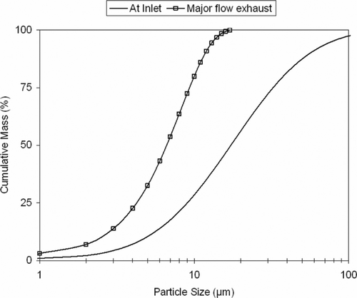
As an example, suppose an IVI with an S/W ratio of 1.75, having the major flow transmission efficiency shown in , is designed to fractionate at a cutpoint size of 10 μ m AD. The intake flow rate is 111 L/min and the major flow is 100 L/min, i.e., the minor flow rate ratio, f, is 10%. Assume the intake aerosol particles are log-normally distributed with a mass median diameter of 18 μ m AD and a geometric standard deviation of 2.5, and further assume the mass concentration at the inlet of the IVI is 100 μ g/m3.
For this example, the cumulative size distributions of aerosol particles at the IVI inlet and at the major flow exhaust port are shown in . Mass median diameter for the particles in the major flow outlet is 7 μ m AD. The rates at which aerosol particles enter and leave the inlet and major flow outlet are 0.185 μ g/s and 0.042 μ g/s, respectively.
Acknowledgments
Funding for this study was partially provided by the Edgewood Chemical Biological Center of the U.S. Army Research, Development, and Engineering Command under Contract DAAD13-03-C-0050. We thank Drs. Edward W. Stuebing and Jerold R. Bottiger of the Army for this support and for their technical guidance. Additional funding was provided by the Aerosol Technology Laboratory of the Texas Engineering Experiment Station and by Accelerator Technology Corporation (ATC), College Station, TX under Contract 06-0997. We wish to express our appreciation for the technical and financial contributions of Dr. Peter M. McIntyre of ATC.
REFERENCES
- ANSYS . 2005 . CFX Release 10: User Manual Cannonsburg, PA, , USA
- Biswas , P. and Flagan , R. C. 1988 . The Particle Trap Impactor . J. Aerosol Sci. , 19 : 113 – 121 .
- Chen , B. T. , Cheng , Y. S. and Yeh , H. C. 1990 . A Study of Density Effect and Droplet Deformation in the TSI Aerodynamic Particle Sizer . Aerosol Sci. Technol. , 12 : 278 – 285 .
- Chow , J. 1995 . Measurement Methods to Determine Compliance with Ambient Air Quality Standards for Suspended Particles . J. Air & Waste Manage. Assoc. , 45 : 320 – 382 .
- Conner , W. D. 1966 . An Inertial-Type Particle Separator for Collecting Large Samples . J. Air Pollut. Control Assoc. , 16 : 35 – 38 .
- Ding , Y. , Ferguson , S. T. , Wolfson , J. M. and Koutrakis , P. 2001 . Development of a High Volume Slit Nozzle Virtual Impactor to Concentrate Coarse Particles . Aerosol Sci. Technol. , 34 : 274 – 283 .
- Dzubay , T. G. and Stevens , R. K. 1975 . Ambient Air Analysis with Dichotomous Sampler and X-ray Fluorescence . Environ. Sci. Technol. , 9 : 663 – 668 .
- Haglund , J. S. and McFarland , A. R. 2004 . A Circumferential Slot Virtual Impactor . Aerosol Sci. Technol. , 38 : 664 – 674 .
- Hari , S. , Hassan , Y. A. and McFarland , A. R. 2005 . Computational fluid dynamics simulation of a rectangular slit real impactor's performance . Nuclear Engineering and Design , 235 : 1045 – 1028 .
- Hering , S. , Gundel , L. and Daisey , J. M. 1997 . A Microslot Impactor for Organic Aerosol Sampling . J. Aerosol Sci. , 28 : 1283 – 1290 .
- Kim , H. T. , Han , Y. T. , Kim , Y. J. , Lee , K. W. and Chun , K. J. 2002 . Design and Test of 2.5 μ m Cutoff Size Inlet Based on a Particle Cup Impactor Configuration . Aerosol Sci. Technol. , 36 : 136 – 144 .
- Lee , S. A. 2001 . A Slit Impactor Utilizing a Transpirated Impaction Surface for Collection of Bioaerosols , M.S. Thesis College Station, TX : Department of Mechanical Engineering, Texas A&M University .
- Loo , B. W. and Cork , C. P. 1988 . Development of High efficiency Virtual Impactors . Aerosol Sci. Technol. , 9 : 167 – 176 .
- Loo , B. W. and Jaklevic , J. M. 1974 . An Evaluation of the ERC Virtual Impactor , Berkeley, CA : Lawrence Berkeley National Laboratory . Report: LBL-2468
- Marple , V. A. , Rubow , K. L. and Behm , S. M. 1991 . A Micro-Orifice Uniform Deposit Impactor (MOUDI) . Aerosol Sci, Technol. , 14 : 434 – 446 .
- McFarland , A. R. , Ortiz , C. A. and Bertch , R. W. J. 1984 . A 10 μ m Cutpoint Size Selective Inlet for Hi-Vol Samplers . J. Air Pollut. Contr. Assoc. , 34 : 544 – 547 .
- Olan-Figueroa , E. , McFarland , A. R. and Ortiz , C. A. 1982 . Flattening Coefficients for DOP and Oleic Acid Droplets Deposited on Treated Glass Slides . Amer. Ind. Hyg. Assoc. J. , 43 : 628 – 639 .
- Peterson , C. M. Aerosol Concentrator and Classifier . U.S. Patent 3,901,798 . 1975 . Filed November 21, 1973, and Issued August 26, 1975
- Romay , F. J. , Roberts , D. L. , Marple , V. A. , Liu , B. Y. H. and Olson , B. 2002 . A High Performance Aerosol Concentrator for Bioaerosol Agent Detection . Aerosol Sci. Technol. , 36 : 217 – 226 .
- Thien , B. F. 2006 . College Station, TX : Aerosol Technology Laboratory, Department of Mechanical Engineering, Texas A&M University . Personal communications
- Thompson , M. W. , Donelly , J. , Grinshpun , S. A. , Juozaitis , A. and Willike , K. 1994 . Method and Test System for Evaluation of Bioaerosol Samplers . J. Aerosol Sci. , 25 : 1579 – 1593 .
- TSI Inc . 2001 . Model 3306 Impactor Inlet Specification Sheet St. Paul, MN, , USA
- U.S. EPA . 1987 . Revisions to the Ambient Air Quality Standards for Particulate Matter . Federal Register , 52 : 24,634 – 24,669 .
- U.S. NRC . 2005 . Sensor Systems for Biological Agent Attacks: Protecting Buildings and Military Bases , Washington, DC : U.S. National Research Council. National Academies Press . Committee on Materials and Manufacturing Processes for Advanced Sensors
