Abstract
Flow instabilities in a virtual impactor designed for bioaerosol concentration (size range about 2 to 10 μ m AD) can seriously degrade performance. When the flow in a 100 L/min circumferential slot virtual impactor (CSVI) was unstable, the transmission efficiency was 30% for 7.2 μ m AD aerosol particles, but when the instability problems were corrected, the transmission efficiency was increased to above 90%. Three-dimensional CFD simulations have been used to examine flows in two CSVIs, a nominal 10 L/min device in which the flow was stable, and the 100 L/min device in which the flow was initially unstable. From the CFD flow patterns in the 100 L/min device, the principal instability was in the minor flow region and was caused by overly rapid flow deceleration, too large of a volume, and too low of a jet velocity in that region. Changes were made to the geometry of the CSVI, and CFD was used as the diagnostic tool to determine when stable flow was achieved. Also, for the 100 L/min unit, wake effects from alignment posts that hold together the two halves of the CSVI propagated into the receiver section, and CFD analyses were used to modify the post locations to optimize the transmission efficiencies for the stable units. Numerical and experimental results show the dynamic ranges (ratio of the largest Stokes number for which the transmission efficiency is 50% to the cutpoint Stokes number) are about 100 for both devices. The peak value of the transmission efficiency for the 100 L/min unit is 95% and that for the 10 L/min device is 97%.
NOMENCLATURE AND ABBREVIATIONS
| AD | = |
Particle aerodynamic diameter |
| C c | = |
Cunningham's slip correction |
| C D | = |
Drag coefficient |
| D p | = |
Particle diameter |
| D 0.5 | = |
Cutpoint particle size, which is the aerodynamic diameter of particle for which the minor flow transmission efficiency is 50% |
| f | = |
Minor flow ratio, represented as: |
| L | = |
Width of air pathway |
| L 1 | = |
Distance to critical zone |
|
| = |
Air flow rate |
|
| = |
Minor flow rate |
|
| = |
Total flow rate |
| R | = |
Radial distance measured from axis of CSVI |
| R c | = |
Critical zone radius, which is the distance from the center of the critical zone (gap between acceleration nozzle and receiver nozzle) to the axis of rotation of the slot |
| R o | = |
Radius of exhaust tube that transports the minor flow |
| Re | = |
Jet Reynolds number based on acceleration jet width and mean velocity |
| Re p | = |
Particle Reynolds number |
| Stk | = |
Stokes number |
| Stk0.5 | = |
Cutpoint Stokes number |
| U | = |
Average air velocity |
|
| = |
Undisturbed fluid velocity at the location of a particle |
| U 1 | = |
Average air velocity at the throat of the acceleration nozzle |
|
| = |
Particle velocity |
| Vol | = |
Volume of the minor flow region |
| W 1 | = |
Acceleration nozzle throat width |
| W 2 | = |
Receiver nozzle throat width |
| φ p | = |
Particle drag force parameter |
| μ | = |
Dynamic viscosity of air |
| ρ a | = |
Air density |
| ρ p | = |
Particle density |
| τ | = |
Time constant of air jet |
1. INTRODUCTION
Virtual impactors are used to concentrate bioaerosol particles, particularly those in the size range of 2 to 10 μ m aerodynamic diameter (AD) (CitationNational Academies Press 2005), because the efficacy of a near-real-time detection and identification concepts can usually be improved by increasing the ambient concentration. The focus of bioaerosol concentration has been on the 2–10 μ m range because of two considerations. First, bioaerosol particles comprised of cells and viruses with sizes less than 2 micrometers are difficult to generate. As a consequence the organisms of interest are generally in the form of clusters, imbedded in matrices, or attached to other particles. However, a virtual impactor concentrator does transmit particles smaller than the lower end of its stated operational range, but it does not concentrate the smallest sizes. Second, particles larger than 10 μ m do not effectively penetrate into the extra-thoracic region of the respiratory system (CitationU.S. EPA 1982), so their potential challenge to human health is smaller than that of the less than 10 μ m AD fraction.
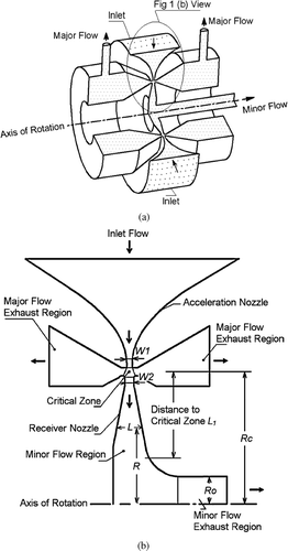
A circumferential-slot virtual impactor (CSVI), , is basically a linear slot wrapped about an axis of rotation to form the equivalent of an endless slot. The plane of symmetry of the slot (acceleration nozzle) is perpendicular to the axis of rotation, . Nomenclature used for the various flow regions of a CSVI is identified in .
FIG 1 Circumferential slot virtual impactor showing geometrical features. The CSVI is symmetrical about the axis of rotation. (a) Cut-away view of device. (b) Schematic diagram showing flow passages and identification of components, regions, and dimensions.
There have been many experimental, theoretical, and numerical studies related to design and characterization of circular-jet and linear-slot virtual impactors (CitationConner 1966; CitationHounam and Sherwood 1965; CitationDzubay and Stevens 1975; CitationMcFarland et al. 1978; Marple and Chien 1980; CitationChen and Yeh 1987; CitationLoo and Cork 1988; CitationSioutas et al. 1994; CitationDing and Koutrakis 2000; CitationMisra et al. 2002; CitationRomay et al. 2002; CitationBergman et al. 2005; CitationMiddhal and Wexler 2006). However, there is little information on the CSVI. CitationHaglund and McFarland (2004) designed and tested a large CSVI unit with a 0.50 mm slot width formed on a 150 mm diameter circle. The overall dimensions of the unit were 269 mm diameter by 78 mm high, and its weight was 3.34 kg. When the unit was operated at 122 L/min, its jet velocity was 8.6 m/s, the major flow pressure drop was 63 Pa, the cut-point was 2.2 μ m AD, and the minor flow transmission efficiency was ≥ 72% over the particle size range of 4.4 to 10 μ m AD. However, when the unit was operated at a flow rate higher than about 140 L/min, acoustical noise was generated and the unit behaved more like an aerosol mixer than a concentrator, i.e., the concentration of aerosol particles with Stokes numbers greater than unity was approximately equal in the major and minor flow paths.
The noise noted by Haglund and McFarland was a constant tone, which suggests the source of the mixing effect in the CSVI was likely acoustic resonance. It was later demonstrated the flow rate associated with the onset of noise could be significantly increased through use of sound-absorbing material at critical locations in the external flow system, particularly the minor flow exhaust tubing (CitationConerly 2005). CitationHan and Moss (1997) visualized water streamlines within a physical model of a virtual impactor and observed the flow was stable in a Reynolds number range of 2,000 to about 7,000, where the Reynolds number (see Nomenclature and Abbreviations section) was based on the acceleration nozzle (slot) characteristics. An interesting observation in their experiments was the flow tended to be unstable when Re was less than 2,000, especially when it was less than 1,000. Gotoh and Masuda (2000, 2001) reported an unstable three-dimensional flow structure in their experiments with rectangular and circular jet virtual impactors and described the unstable flow patterns in the minor region. They focused on instability as an adverse pressure gradient phenomenon and modified the geometry in the minor region to accelerate the flow, and correspondingly to decrease the downstream pressure. The impactor performance was improved by these modifications; however, the instability phenomenon was not quantified.
In this study, numerical simulations were used to simulate the flows in two CSVI units to determine whether they were stable. CFD was also used as a tool to predict the aerosol transmission of the two units, one of which has a nominal inlet flow rate of 10 L/min and the other has a nominal inlet flow rate of 100 L/min. These two devices will be referred to herein as CSVI-10 and CSVI-100. Both devices are much smaller than that of CitationHaglund and McFarland (2004); with the dimensions of CSVI-10 being 41 mm diameter by 58 mm high, and its weight being 150 g. For the CSVI-100 device, the dimensions are 73 mm diameter by 91 mm high and its weight is 586 g.
The flow in the 10 L/min unit (CSVI-10) was stable; however, CFD was used as a tool for upgrading the unit geometry to improve the coarse particle (minor flow) transmission efficiency and the range of particle sizes over which high transmission could be achieved. Experimental testing was used to validate the predicted sampling characteristics. For the 100 L/min system, experimental operation of an early version of the unit (CSVI-100A) produced a pulsing noise, and the minor flow transmission efficiency for high-inertia particles was significantly lower than anticipated. Simulations were used to find possible reasons and solutions for this instability problem. In a subsequent upgraded unit, CSVI-100B, simulations showed the flow was stable, no noise was observed during experimental operation, and the coarse particle transmission efficiency was significantly improved; however, there was deposition (about 25% loss for 10 μ m AD particles) caused by wakes from the posts that support and align the two halves of the CSVI unit. CFD was used to calculate the flow field and analyze the influence of the wakes on particle deposition. A new unit, CSVI-100C, with an improved post design, was fabricated and tested. Computational and physical experiments were performed on this unit, and good agreement was obtained for the two approaches. gives a summary of the major features of the two CSVI devices and their various renditions.
TABLE 1 Summary of the CSVI units
2. CSVI: OPERATIONAL PRINCIPLE AND DESIGN OBJECTIVES
The CSVIs of this study have axisymmetric geometries, , and when the flow is stable, they have flow fields similar to that shown in . From the viewpoint of the fluid, the air flow accelerates in the inlet region and enters the critical zone where about 90% of the flow turns and is exhausted as the major flow, while the remaining 10% of the mass flow is exhausted as the minor flow. In general, low-inertia particles are transported with the major flow and high-inertia particles are exhausted with the minor flow, where the distinction between low- and high- inertia is based on the Stokes number, Stk:
FIG 2 A cross-section of a 3-D simulation showing stable flow in a CSVI. (a) Velocity contours. (b) Path-lines in the critical zone. The color coding is used to show the velocity magnitude in (a) and initial location of a line source of fluid particles in the acceleration nozzle in (b).
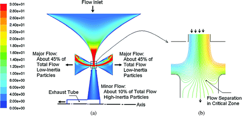
When the minor flow enters the receiver nozzle, which generally has a larger width than the acceleration nozzle, the flow expands rapidly, . In turn, the average velocity, U, undergoes a significant decrease, where the average velocity is:
The average air velocity and, correspondingly, the static pressure in the receiver nozzle and minor flow region will depend on the geometrical parameters R and L (). After the initial deceleration, as the minor flow approaches toward the axis of rotation of the CSVI, the typical design will have an expanding channel width, L. As the radius R decreases, the velocity may either increase or decrease depending on the change in L with respect to R.
The flow Reynolds numbers, Re, of the CSVIs used in this study were between 460 and 1040, which are assumed to be in the laminar range. Here, the Reynolds number is defined as:
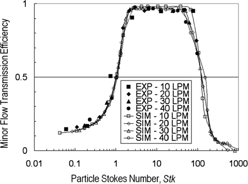
The devices in this study are intended to have cutpoints of about 2.2 μ m AD; however, they also need to collect particles with sizes of at least 10 μ m AD. A single 10 μ m bioaerosol particle cluster may contain on the order of a thousand 1 μ m cells, and because devices that detect or identify the concentrated bioaerosol samples are typically sensitive to the total number of cells (mass concentration of bioaerosol particles), better detection or identification can generally be accomplished if the larger particles (e.g., 10 μ m AD) are efficiently concentrated (CitationNational Academies Press 2005). This implies a wide dynamic range is required for the CSVI units, where the dynamic range is the ratio of the upper limit of Stokes number for which the minor flow transmission efficiency is at least 50% to the cutpoint Stokes number. The upper limit is imposed by deposition of high-inertia particles on the internal surfaces of a virtual impactor. The dynamic range can be illustrated by reference to , which shows the performance of a typical CSVI in this study, where the minor flow transmission efficiency curve has an inverted “U” shape. In this particular case (), the cutpoint Stokes number is about 1 and the upper Stokes number is about 100, giving a dynamic range of about 100.
3. THREE-DIMENSIONAL NUMERICAL SIMULATION
Fluent 6.2.14 (Fluent Inc., Lebanon, NH, USA) was used to perform 3-D simulations using the appropriate models to calculate the air flow fields and particle trajectories. The laminar model together with higher-order discretization schemes was used to obtain the air flow fields and check flow stability. For situations where particle trajectories were involved, after calculating the flow field, a Lagrangian Discrete Phase Model was used to characterize the trajectories so the minor flow particle transmission efficiency could be determined. About 4,000 particles were released from the inlet area of the CSVI in each particle size trajectory analysis. The minor flow transmission efficiency for a given particle size was calculated from ratio of the number of particles exhausted from the minor flow tube to the total number of particles (4,000) that enter the CSVI unit. The particle concentration was assumed to be dilute so the particles have no influence on the continuous phase (air), i.e., it is a one-way coupling simulation.
With respect to the solver and solution control, a second-order upwind scheme was selected for discretization of variables such as momentum. SIMPLEC (CitationVandoormaal and Raithby, 1984) was used for pressure-velocity coupling because it provides a rapid convergence for the solution. A velocity boundary was set for the inlet based on flow rate and inlet surface area. Mass flow ratio boundaries were set for the minor and major outflows.
The only external force considered in the equations used to calculate the motion of particle trajectories was the fluid drag force:
A CSVI unit has axisymmetric geometry and a 2-D axisymmetric approach could be used to study its performance if the flow were stable and there were no 3-D features, i.e., if the flow developed only in the radial direction and there were no circumferential variations of any parameter (e.g., velocity). However, if the flow is unstable or if angular-direction flow features are present, 3-D simulation is required. The benefit of a 3-D simulation is its ability to capture an instantaneous 3-D flow pattern, which allows a stable flow to be easily distinguished from an unstable flow, as illustrated in .
FIG 4 Velocity contours at cross sections of CSVI units. (a) CSVI-100A illustrating unstable flow. (b) CSVI-10A illustrating stable flow.
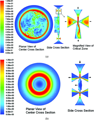
Slots of the CSVI units in this study have a large ratio of circumferential length to slot width. For example, CSVI-100A has a critical-zone radius of about 35.6 mm (1.4 inches) and a slot width of 0.508 mm (0.020 inches), which is equivalent to a long narrow slot with an aspect ratio of about 440. When Gambit 2.2.30 (Fluent Inc., Lebanon, NH, USA) is used to create a structured mesh, the aspect ratio of the cells should not be larger than about 20. The aspect ratio of the CSVI unit required a mixed mesh to limit the cell numbers in a reasonable range because unsteady flow analysis was necessary. Meshes with about 1.2 M mixed cells were used for the 3-D simulations.
4. EXPERIMENTAL METHODS
The CSVI units were experimentally tested to validate the numerical predictions of sampling performance. A six-jet Collison nebulizer (Model CN311, BGI Inc., Waltham, MA) was used to aerosolize monodisperse fluorescent polystyrene particles, PSL (Duke Scientific, Palo Alto, CA), with sizes in the range of 0.5 to 2.0 μ m. A vibrating orifice aerosol generator (VOAG) (Model 3450, TSI Inc., Shoreview, MN) was used to generate monodisperse liquid droplets, with larger sizes, from solutions containing ethanol, oleic acid, and a fluorescent tracer. The constancy and quality of aerosol output from the generators were monitored with an aerodynamic particle sizer, APS (Model 3321, TSI Inc, Shoreview, MN).
Minor flow transmission efficiency is calculated from a comparison of the amount of particulate matter that enters a CSVI to the amount that is exhausted in the minor flow. Aerosol samples were alternately collected on a reference filter, which sampled the aerosol in lieu of the CSVI, and then on filters placed at the outlets of the minor flow of the CSVI during its operation. Glass fiber filters (Type A/D, Pall Corp., East Hills, NY) were used to collect the aerosol particles. For tests with PSL particles, the filters were submerged in ethyl acetate for 4–5 hours to dissolve the particles and elute the fluorescent tracer, while the filters containing liquid particles produced by the VOAG were soaked in an isopropyl and water solution to elute the fluorescent tracer. The solutions were analyzed with a fluorometer (Model FM109535, Quantech Barnstead International, Dubuque, IA) and the minor flow transmission efficiency, η mf , for the particle size being tested, was calculated from:
5. RESULTS AND DISCUSSION
5.1. CSVI-10 Performance
3-D simulations of the flow in the first version of the 10 L/min CSVI (CSVI-10A) showed the flow was stable, . However, in physical experiments it was found the minor flow transmission efficiency dropped precipitously for particle sizes somewhat larger than about four times the cutpoint size, resulting in a smaller dynamic range than desired. Simulations showed this was caused by particle losses at the entry of the minor flow exhaust region where particles with high inertia would strike the opposite-side of the exhaust tube. The unit was re-designed to reduce the air velocity at the critical zone by increasing the critical zone radius (R c in ), and by enlarging the diameter of the exhaust tube (R o ). The revised unit (CSVI-10B) was tested and shown to have robust performance. It has both a wide dynamic range (about 100) and it can operate at flow rates up to 40 L/min. Increasing the flow rate can be considered to be a means of reducing the cutpoint size, which is about 2.2 μ m AD at the flow rate of 10 L/min, and is therefore about 1.1 μ m at the flow rate of 40L/min.
Experimental results and numerical predictions are shown in . The numerical and experimental methods agree well at the four different flow rates that range from 10 to 40 L/min. All tests were conducted at a minor flow ratio (minor air flow rate/inlet air flow rate) of 10%. For all flow rates, the cutpoint Stokes number, Stk 0.5, is about 1.0.
The numerical simulations provide accurate predictions for the different regimes of the minor flow transmission efficiency curve including the increasing, flat, and dropping regions. The increasing region shows a typical efficiency curve of an inertia-based fractionator, where the efficiency increases as the Stokes number increases. The flat region is where the collection is maintained at high values for large-inertia particles. The drop of the transmission efficiency for high-inertia particles is caused by the crossing-trajectory phenomenon (CitationHari et al. 2007).
Because the efficiency data for all flow rates fit well onto one curve, it implies that the transmission efficiency for this geometrical configuration is primarily a function of the particle Stokes number and is almost independent of the flow Reynolds number over the range of 460 to 1840.
5.2. CSVI-100A Performance
5.2.1. CSVI-100A Operational Characteristics
In physical experiments with CSVI-100A, the unit generated a pulsing noise and its minor flow transmission efficiency was only about 30% for 7.2 μ m AD (Stk = 9.2) particles, a size for which the transmission efficiency should be much higher. Irregular patterns of particle deposition were observed on internal surfaces. The pulsing noise was different than the constant tone observed by CitationHaglund and McFarland (2004) with their apparatus, indicating the source of the noise was of a different nature. Design features (nozzle shapes, critical dimensions, and, inlet and exhaust flow patterns) are different in the unit of Haglund and McFarland and the CSVI-100A device, so identical noise problems should not be expected.
A 3-D simulation was conducted to analyze the flow field in CSVI-100A and unusual features were observed in the velocity contours, . The CSVI unit has an axisymmetric geometry and the flow should be axisymmetric. Also, when the jet from the acceleration nozzle enters the receiver nozzle, the flow should develop symmetrically in the center of the receiver region, which is the type of stability found in the CSVI-10 units, . However, in the receiver region of CSVI-100A, the jet is non-symmetrical.
The velocity contours shown by the simulation in represent steady simulation results. Movies created from time-sequenced simulations show there is a strong flow in the circumferential direction and unsteady behavior of the jet entering the receiver section. The latter phenomenon is illustrated in , where a time-sequenced set of simulation results shows an unstable jet in the receiver section of CSVI-100A, which leads to the jet striking the left wall. Further time sequenced velocity profiles would show the jet does not remain attached to the wall, but fluctuates across the receiver section.
FIG 5 A time sequence of velocity contours at one cross-section of CSVI-100A. Simulations represent snapshots in time.
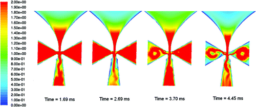
This type of jet causes the actual velocity in the critical zone to be much higher than the calculated average velocity at the acceleration slot, U 1, based on the flow rate and width of the acceleration nozzle (W 1). When the flow is stable, as in the CSVI-10A, the maximum velocity in the critical zone, just above the receiver nozzle, is about 18 m/s (1.2 U 1). However, when the flow is unstable, it also has a strong component in the angular direction which results in a much higher velocity magnitude than when the flow is stable and only in the radial direction. The average velocities in the entrance slots of CSVI-10A and CSVI-100A are both 14.6 m/s, but, the maximum velocity in the critical zone of CSVI-100A is about 32 m/s (2.2 U 1), which appears in a few local elements in the circumferential direction.
5.2.2. Causes of Flow Instabilities in CSVI-100
There are several potential causes for the instabilities, including resonance of pressure pulsations from a blower. The flow through CSVI-10A and CSVI-10B were stable, and in experiments the same test blowers were used with all devices. Also, the noise was pulsating rather than a constant tone as would be expected if the source of the noise was resonance of blower-induced pressure pulses, so it was assumed unlikely the blowers were the source of the instability problem with CSVI-100A. Because the designs of the critical regions are similar for the CSVI-10A and the CSVI-100A units, we assumed it was the geometrical features and the behavior of the ensuing jet that caused the unstable flow. This assumption was borne out by development of the CSVI-100C device (discussed later), in which stability was achieved by design modifications to the receiver section.
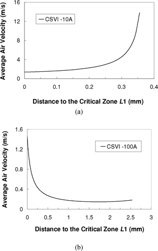
Average air velocities in the minor-flow regions of CSVI-10A and CSVI-100A are shown in . Here the abscissas show the distance from the critical zone (identified as L 1 in ). When the flow is approaching the axis from the minor region of CSVI-10A, it is accelerating, which results from the radius R decreasing faster than the expansion of the channel width, L. This implies the static pressure gradient (dP/dL) tends to be negative in the direction of flow. In contrast, for CSVI-100A, the average velocity is decreasing and the air is decelerating because the radius decreases slower than the width expansion, which produces a positive pressure gradient in the flow direction in the minor flow region. A negative pressure gradient tends to assist flow stability, while a positive gradient could make the flow unstable.
FIG 6 Average air velocity as a function of L1, the distance from a selected location in the receiver nozzle to the center of the critical zone. (a) CSVI-10A. (b) CSVI-100A.
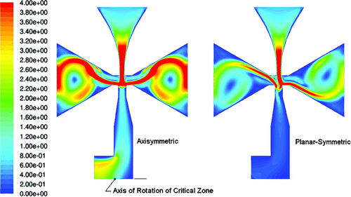
To verify the importance of the pressure gradient, two cases were simulated using axi-symmetric (CSVI) and planar-symmetric (linear slot virtual impactor, LSVI) geometries with the same cross section configuration as the CSVI-10B unit, . In the axisymmetric unit, the flow accelerates significantly in the minor flow region due to the decreasing radius and there is a negative pressure gradient towards the axis. The simulation shows that the flow in this case is stable and that the jet enters the receiver symmetrically and develops smoothly. However, in the planar-symmetric case, the cross-sectional area of the flow is controlled only by the expansion of the diffuser, so the pressure gradient in the flow direction is positive. This causes flow asymmetry in the major and minor flow regions, with the jet momentarily striking one wall of the receiver section. The two different flows suggest that the pressure gradient is an important factor in the stability of the flow in virtual impactors, and that the CSVI should be inherently more stable than an LSVI.
FIG 7 Different flow behaviors in axisymmetric (CSVI) and planar-symmetric (Linear Slot Virtual Impactor) slots. Slot velocities and cross-section dimensions are the same; however the flow in the CSVI converges towards the axis of rotation of the slot, which renders it more stable.
Another possible reason for flow instability in the CSVI-100A unit is it has a relatively large volume downstream of the receiver nozzle, where it is desired to produce a uniform velocity profile. The jet entering the receiver nozzle has an initial velocity of about 14.6 m/s, but it comprises only 10% of the total mass flow. The receiver nozzle is wider than the acceleration nozzle, so the jet would ideally decelerate to about 1.2 m/s in the straight section of the receiver nozzle. The jet enters the minor flow region and travels toward the axis of the CSVI, where it may break up. There is a timescale, τ, based on the initial jet velocity, which can be used to indicate the decay of the jet. A parameter defined as ![]() τ/Vol, where
τ/Vol, where ![]() is flow rate, Vol is minor region volume, and τ is a jet time scale, can be considered as the ratio of the dynamic jet momentum to the inertia of the air residing in the minor region. We assume if a developing jet has a larger value of
is flow rate, Vol is minor region volume, and τ is a jet time scale, can be considered as the ratio of the dynamic jet momentum to the inertia of the air residing in the minor region. We assume if a developing jet has a larger value of ![]() τ/Vol, it will be more stable because it has a larger initial momentum and can penetrate farther into the minor region before breakup. The value of
τ/Vol, it will be more stable because it has a larger initial momentum and can penetrate farther into the minor region before breakup. The value of ![]() τ/Vol for CSVI-10A is about 25 times to that of the CSVI-100A, which suggests the minor region volume in CSVI-100A is too large relative to its jet characteristics.
τ/Vol for CSVI-10A is about 25 times to that of the CSVI-100A, which suggests the minor region volume in CSVI-100A is too large relative to its jet characteristics.
5.3. CSVI-100B Performance
A new unit, CSVI-100B, was designed with a smaller value of ![]() τ/Vol, which was achieved by using a shorter critical zone radius, and a smaller expansion angle (11° verses the previously used 15°) in the minor flow region. The smaller expansion angle reduces the magnitude of the adverse pressure gradient. To maintain the same flow rate and cutpoint as the CSVI-100A unit, the average velocity of the jet at the slot of the acceleration nozzle was increased to about 21 m/s, which is larger than that in the CSVI-100A (14.6 m/s). The higher velocity implies the jet in the CSVI-100B could penetrate farther into the minor flow region before breakup. The stability of the upgraded design was verified with 3-D simulations that showed no asymmetrical behavior, including no flow in the circumferential direction.
τ/Vol, which was achieved by using a shorter critical zone radius, and a smaller expansion angle (11° verses the previously used 15°) in the minor flow region. The smaller expansion angle reduces the magnitude of the adverse pressure gradient. To maintain the same flow rate and cutpoint as the CSVI-100A unit, the average velocity of the jet at the slot of the acceleration nozzle was increased to about 21 m/s, which is larger than that in the CSVI-100A (14.6 m/s). The higher velocity implies the jet in the CSVI-100B could penetrate farther into the minor flow region before breakup. The stability of the upgraded design was verified with 3-D simulations that showed no asymmetrical behavior, including no flow in the circumferential direction.
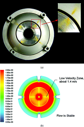
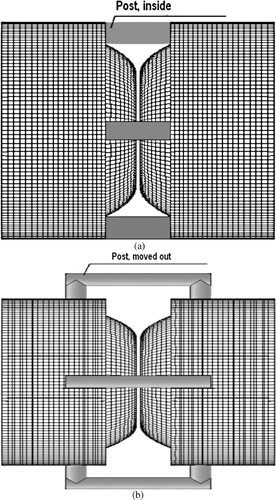
A CSVI-100B device was fabricated and subjected to physical tests. There was no longer a pulsing noise during operation; however, the maximum minor flow transmission efficiency was only 78% (for 6 μ m AD particles), which was lower than expected. When the internal wall deposition was checked, it was found the majority of the wall was clean; however, narrow patterns of deposition were observed downstream of each of the four posts that align and support the two halves of the CSVI, . This deposition was verified with a simplified numerical simulation in which the four posts were included in the geometry of the CSVI-100B unit. The velocity contour at the center cross-section of the CSVI unit is shown in , which indicates low-velocity flow in the wake of each post, where the velocity was about 1.45 m/s as compared with 2.8 m/s outside of the wake. The effect propagates into the minor flow region, where the velocity deficit is also noted. Presumably, the disturbance in the wake together with the velocity gradients, cause the deposition patterns.
5.4. CSVI-100C Performance
Numerical simulations were then conducted to optimize the size and location of the posts to reduce the effect of the wake flow of the posts. A new unit, CSVI-100C, was designed with the posts moved radially outwards about 12 mm (0.47 inches). A comparison of the post locations in the CSVI-100B and CSVI-100C units is shown in . The simulations showed the modification significantly reduced the wake effect of the posts.
FIG 9 Post configuration for CSVI-100 unit. (a) CSVI-100B with the posts close to the body. (b) CSVI-100C with the posts moved radially outward.
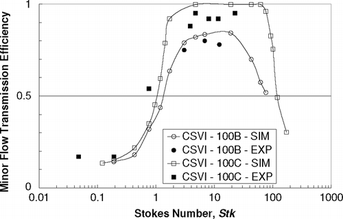
A CSVI-100C device was then fabricated and tested. With reference to , where the minor flow transmission efficiencies of CSVI-100B and CSVI-100C are compared, the maximum transmission efficiency of CSVI-100C is about 95%, whereas the maximum transmission efficiency of CSVI-100B was 78%. Also, the dynamic range of CSVI-100C is about 100. The numerical predictions agree reasonably well with experiments for both units, i.e., differences of transmission efficiencies are within about 10%, with the simulations over-predicting experimental results.
6. CONSIDERATION OF FLOW STABILITY IN THE DESIGN OF VIRTUAL IMPACTORS
Flow stability is a critical factor for achieving suitable performance of a virtual impactor and it must be considered in the design of virtual impactors with low Reynolds number flows. Experimentally, there are several symptoms of instabilities, including acoustical noise emanating from the inside of the unit, unexpected low minor flow aerosol transmission efficiency, and aerosol deposition on surfaces, which from inertial considerations, would not be expected to exhibit particle collection. Numerically, indications of instabilities are associated with asymmetric flow patterns, momentary striking of jet to the side walls in the receiver section, and unusually high flow velocities in the critical zone. These manifestations disappear if the flow is stable.
If the flow is found to be unstable, there are several steps that can be taken to resolve the problem. An adequate negative pressure gradient must be built into the minor flow region of the virtual impactor in the flow direction. Also a higher jet velocity and smaller minor flow volume can reduce the potentiality of unstable flow by causing the jet to reach farther into the minor flow region before breakup. CFD techniques can be used to check if the flow is stable after device is modified, and to provide accurate performance predictions for a virtual impactor operated with a laminar jet.
7. SUMMARY
CFD was used to simulate operation of a 10 L/min CSVI and the results showed stable flow although the dynamic range was limited because of a crossing trajectory effect. Modifications were made to the design and a subsequent unit, CSVI-10B was fabricated. Physical experiments verified the CFD predictions, with the unit having excellent performance including a dynamic range of about 100 and a peak minor flow transmission efficiency of 97% associated with a particle size of 6.2 μ m AD. Also, CSVI-10B could be operated over a flow rate range of 10 to 40 L/min with the similar performance in terms of minor flow transmission efficiency as a function of Stokes number. Cutpoint particle size, which is about 2.2 μ m AD at a flow rate of 10 L/min, can be reduced to about 1.1 μ m AD at a flow rate of 40 L/min.
For a 100 L/min CSVI, which had a larger physical size and somewhat different geometrical parameters, flow instability problems were observed in physical experiments, which problems are manifested in the generation of acoustical noise and a significant deterioration in performance. The flow field in the 100 L/min CSVI unit was simulated and possible causes for the problems were analyzed. Changes in the pressure gradient and volume of the minor flow region, and an increase in the jet velocity solved the stability problem.
Particle losses created by wakes downstream of support posts were also analyzed with CFD. Based on results from the CFD analyses, an improved design was developed, CSVI-100C, which has high minor flow transmission efficiency (95% for a particle size of 10.9 μ m AD) and a dynamic range of about 100. The predicted performance of the CSVI units was compared with experimental results and good agreement was obtained.
Stable flow is an important consideration in the design of CSVI units reported in this study, and that factor may also be necessarily considered in other virtual impactors. This may be especially true for linear slot virtual impactors, which are inherently less stable than CSVI devices. Also wakes from the presence of obstacles in the flow (e.g., support and alignment posts) may cause losses. However, there is no universal solution for all the devices that may have stability or wake problems due to different design features and flow conditions. But, as evidenced by this study, CFD is a useful approach for examining the flow patterns and predict particle behavior in virtual impactor concentrators, and then provide the basis for determining the efficacy of design modifications in resolving instability problems.
Acknowledgments
This work is supported by the Edgewood Chemical Biological Center of the U.S. Army Research, Development, and Engineering Command under Contract DAAD13-03-C-0050. The authors wish to express their appreciation to Drs. Edward W. Stuebing and Jerold R. Bottiger of the Army for their guidance and support. We wish to acknowledge the design and fabrication contributions of Messrs. Darrick Niccum and Philip Poeschl of TSI Inc., and the testing help of Messrs. Refugio Isaguirre, Clinton Adams, and Daniel LaCroix of Texas A&M University. We also wish to thank Dr. John Haglund, of the Applied Research Laboratory of the University of Texas for his efforts and guidance.
REFERENCES
- Bergman , W. , Shinn , J. , Lochner , R. , Sawyer , S. , Milanovich. , F. and Mariella , R. Jr. 2005 . High Air Flow, Low Pressure Drop, Bio-Aerosol Collector Using a Multi-Slit Virtual Impactor . J. Aerosol Sci , 36 : 619 – 638 .
- Chen , B. T. and Yeh , H. C. 1987 . An Improved Virtual Impactor: Design and Performance . J. Aerosol Sci , 18 ( 2 ) : 203 – 214 .
- Conerly , S. C. 2005 . Multi-Stage Liner Slot Virtual Impactor for Concentration of Bioaerosols. M.S. Thesis , College Station, TX : Department of Mechanical Engineering, Texas A&M University .
- Conner , W. D. 1966 . An Inertial-Type Particle Separator for Collecting Large Samples . J. Air Pollut. Contr. Assoc. , 1 : 35 – 38 .
- Ding , Y. and Koutrakis , P. 2000 . Development of a Dichotomous Slit Nozzle Virtual Impactor. . J. Aerosol Sci , 31 ( 12 ) : 1421 – 1431 .
- Dzubay , T. G. and Stevens , R. K. 1975 . Ambient Air Analysis with Dichotomous Sampler and X-Ray Fluorescence. . Environ. Sci. Technol. , 9 : 663 – 668 .
- Fuchs , N. A. 1964 . The Mechanics of Aerosols , New York : Pergamon Press .
- Gotoh , K. and Masuda , H. 2000 . Improvement of the Classification Performance of a Rectangular Jet Virtual Impactor. . Aerosol Sci. Technol , 32 : 221 – 232 .
- Gotoh , K. and Masuda , H. 2001 . Development of Annular-Type Virtual Impactor. . Powder Technol. , 118 : 68 – 78 .
- Haglund , J. S. and McFarland , A. R. 2004 . A Circumferential-Slot Virtual Impactor. . Aerosol Sci. Technol , 38 : 664 – 674 .
- Han , R. and Moss , O. R. 1997 . Flow Visualization inside a Water Model Virtual Impactor. . J. Aerosol Sci. , 28 : 1005 – 1014 .
- Hari , S. , McFarland , A. R. and Hassan , Y. A. 2007 . CFD Study on the Effects of the Large Particle Crossing Trajectory Phenomenon on Virtual Impactor Performance. . Aerosol Sci. Technol. , 41 : 1040 – 1048 .
- Hinds , W. C. 1999 . Aerosol Technology, Properties, Behavior, and Measurement of Airborne Particles. , 2nd Ed. , New York : John Wiley & Sons .
- Hounam , R. F. and Sherwood , R. J. 1965 . The Cascade Centripeter: A Device for Determining the Concentration and Size Distribution of Aerosols . Amer. Ind. Hyg. Assoc. J. , 26 : 122 – 131 .
- Loo , B. W. and Cork , C. P. 1988 . Development of High Efficiency Virtual Impactors. . Aerosol Sci. Technol. , 9 : 167 – 176 .
- Masuda , H. , Hochrainer , D. and Stober , W. 1979 . An Improved Virtual Impactor for Particle Classification and Generation of Test Aerosols with Narrow Size Distributions. . J. Aerosol Sci. , 10 : 275 – 287 .
- McFarland , A. R. , Ortiz , C. A. and Bertch , R. W. 1978 . Particle Collection Characteristics of a Single-Stage Dichotomous Sampler. . Environ. Sci. Technol. , 12 ( 6 ) : 679 – 682 .
- Middhal , P. and Wexler , A. S. 2006 . Design of a Slot Nanoparticle Virtual Impactor. . Aerosol Sci. Technol. , 40 : 737 – 743 .
- Misra , C. , Kim , S. , Shen , S. and Sioutas , C. 2002 . A High Flow Rate, Very Low Pressure Drop Impactor for Inertial Separation of Ultrafine from Accumulation Mode Particles. . J. Aerosol Sci , 33 : 735 – 752 .
- National Academies Press . 2005 . Sensor Systems for Biological Agent Attacks: Protecting Buildings and Military Bases , Washington, DC : National Academies Press . Committee on Materials and Manufacturing Processes for Advanced Sensors. U.S. National Research Council
- Patankar , S. V. 1980 . Numerical Heat Transfer and Fluid Flow , Washington, D.C. : Hemisphere .
- Romay , F. J. , Roberts , D. L. , Marple , V. A. , Liu , B. Y. H. and Olson , B. 2002 . A High Performance Aerosol Concentrator for Bioaerosol Agent Detection. . Aerosol Sci. Technol. , 36 : 217 – 226 .
- Sioutas , C. , Koutrakis , P. and Burton , R. M. 1994 . Development of a Low Cutpoint Slit Virtual Impactor for Sampling Ambient Fine Particles. . J. Aerosol Sci. , 25 : 1321 – 1330 .
- U. S. EPA . 1982 . Air Quality Criteria for Particulate Matter and Sulfur Oxides. Volume I. , Research Triangle Park, NC : United States Environmental Protection Agency . EPA-600/8-82-029A
- Vandoormaal , J. P. and Raithby , G. D. 1984 . Enhancements of the SIMPLE method for predicting incompressible fluid flows. . Numer. Heat Transfer , 7 : 147 – 163 .
