Abstract
Measurements and simulations of an industrial outside vapor deposition process as used for the manufacture of optical wave guides were performed. Deposition efficiencies, flame temperatures, and gas velocities were measured. The hydrogen flame reaction was modeled by calculating the turbulent flow including a combustion model and using a computational fluid dynamics (CFD) solver to compute flow velocities, turbulence and temperatures in the flame. These results were compared with experimental data and reasonable agreement was found. The produced SiO 2 particles with predefined size were tracked through the flow field and it was determined whether they hit the surface of the cylindrical target or pass it.
Three flame configurations were investigated and the model could predict well the trends of the deposition efficiencies for the different flames. The differences in flame velocities and turbulence levels for the different configurations assisted the explanation of the performances of the flames. Turbulence levels were different for the three flames and it was concluded that for turbulent deposition processes the thermophoretic force that drives particles towards colder surfaces is less important than for laminar deposition processes.
1. INTRODUCTION
For the production of optical waveguide fibers, tubes made from synthetic quartz glass are used as summarized by CitationLi (1985). Especially in the case of substrate tubes for inside chemical vapor deposition (CVD)–processes, as modified CVD (MCVD) or plasma CVD (PCVD), there is a demand for impurity levels in the ppb-range. Therefore, these tubes are made from synthetic SiO2, which is produced in a flame hydrolysis process from silicon containing compounds (e.g., silicon tetrachloride). The nanoparticles are formed from a precursor in an oxy-hydrogen flame with the burner moving axially and deposited on a rotating target, so that a porous body, the so called soot body, is built. After the deposition process, this soot body is dehydrated thermally and chemically in a halogen enriched atmosphere and afterwards sintered to get a solid quartz glass cylinder. A significant amount of particles, produced in the flame, are not deposited and lost for the product. Hence, understanding and improving this process is linked with an enormous economic benefit. Therefore, in the last decade considerable theoretical, numerical, and experimental research has been carried out to improve the understanding of heat and mass transfer during the outside vapor deposition (OVD) process. CitationBautista et al. (1990) measured deposition efficiencies and growth rates for a laminar torch depositing particles on a cylindrical target. They also presented an analytical model from older references, which was based on the thermophoretic particle velocity, and predicted satisfactorily their measured deposition efficiencies, which were around 40–70% depending on the details of the configurations. They improved the model by taking into account a Gaussian distribution of the particle concentration exiting the burner and then predicted well the deposition efficiencies as a function of target diameter. However, their model needed measured particle velocities as input.
CitationGraham and Alam (1991) summarized some older work on the OVD process and studied experimentally the deposition efficiencies for variations of carrier gas flow rates, burner-cylinder distances, and fuel equivalence ratios. They suggested optimum operation parameters for their process, which resulted in a deposition efficiency of 83% for burner-cylinder distance of 5.5D, with D being the diameter of the target. This efficiency decreased nearly linearly with larger or smaller distances between burner and target.
CitationTsai et al. (1995) studied the thermophoretic transport process towards a disk and overpredicted the deposition rates by around 20% but captured the well-known trend that with increased target size the deposition rate increases nearly linearly. Wu and Greif (1996) modeled the deposition of Silica particles using a two dimensional numerical flow computation scheme. They also included the SiCl4 and methane oxidation to calculate the laminar flame structure. For the thermophoretic deposition model they assumed a range of surface temperatures for the cylindrical target and modeled the deposition process presented by CitationBautista et al. (1990). However, their analysis resulted in far too low deposition rates in comparison with measurements, which they explained by the two dimensionality of the model.
CitationHong and Kang (1998) used a numerical fluid dynamics model for calculating the two and three dimensional flow and particle deposition from a hot jet impinging on a cylinder and considered also heat transfer within the target. The two and three dimensional flow showed differences and the recirculation zone behind the cylinder was smaller for the real three dimensional case. They investigated the influence of different process parameters like traversing speed and found that deposition increased when the surface temperature was reduced. CitationCho et al. (1998) studied experimentally heat transfer and particle deposition and found that an increased speed of the axial movement of the burner reduced surface temperatures, which caused the deposition efficiency and rate as well as the porosity to increase.
CitationTandon and Balakrishnan (2005) recently presented a modeling scheme for predicting thermophoretic deposition with thermophoresis as dominant particle deposition mechanism. They used several assumptions in their modeling, e.g., for the flame spread and temperature as well as the particle distribution. They slightly overpredicted the measured deposition on a cylinder from the laminar flame torch of CitationBautista et al. (1990) and also studied multiple flame configurations. In another paper, CitationTandon et al. (2003) gave a detailed theoretical framework for their modeling work and predicted well the heat flux to a cylindrical surface and the soot layer thickness for different flames. Some of their assumptions, which were well justified, are also relevant for the current work, i.e., that depositing particles contribute only around 3% to the total heat flux to the cylinder and that Brownian diffusion does not contribute to the deposition process, since the sub-layer where it is important is very thin. They also pointed out the analysis of CitationRosner and Park (1988), who showed that inertial effects can increase the deposition efficiencies. For a particle mass loading, defined as ratio of particle mass to the mass of the carrier gas, of 0.7 they predicted an increase of deposition efficiency by up to a factor of 2 compared to the dilute limit. They explained this trend by changes of the boundary layer structure near the axisymmetric stagnation point due to the additional mass of the particles. For the case of CitationTandon et al. (2003) this inertial effect augmented the deposition efficiency by around a factor of 1.2.
All the above experiments and calculations were performed with laminar flames. However, for industrially scaled OVD processes, usually larger flow rates are applied and the flows become turbulent. Hence, one of the purposes of the current work was to model the particle mass fraction distribution in turbulent flames and the resulting deposition on a cylindrical target. In addition, past modeling attempts often showed satisfactory agreement with experiments, however did not rely on first principles and assumed general correlations based on, for example, the Nusselt numbers to describe thermophoretic deposition. In the current work for the first time, to the authors' knowledge, the flame structure of a turbulent and reacting flame and resulting particle trajectories are calculated from first principles to derive deposition efficiencies. The article is structured as follows: Section 2 describes the configuration of the three flames considered and the measurement techniques for deposition efficiencies and surface temperatures. Section 3 describes the numerical methods applied to compute the flame structure and the particle trajectories. Section 4 presents experimental results and section 5 presents the simulations and section 6 discusses the deposition mechanism in the turbulent flow together with the role of thermophoresis. The article ends with a summary of the main findings.
2. EXPERIMENTAL SET-UP
2.1. Burner Specifications
For measuring the particle deposition efficiencies, a laboratory setup consisting of a single burner and a target tube made from alumina oxide with diameter D, that can be rotated and oscillated along its axis, was used. The diameter of the target will be used to present all other lengths in non-dimensional form throughout this paper. A schematic overview of the setup is shown in . The gas flows through the different burner nozzles where controlled by mass flow controllers, while the Silicon tetrachloride vapor is generated in an evaporator and injected through the center pipe. The whole setup is placed in a chamber, which is ventilated by a homogeneous upward air flow with approximately 1 m/s to exhaust the not deposited particles and the gaseous reaction products. The chamber has four windows, which allowed Particle Image Velocity measurements in a 90° arrangement. To study the effect of wall surface temperatures, liquid nitrogen could be passed through the cylindrical target, which was made of alumina oxide with a wall thickness of approximately 5 mm.
FIG. 1 (a) Experimental set-up and (b) flame configurations (flames 1a, 2, and 3 from left to right).
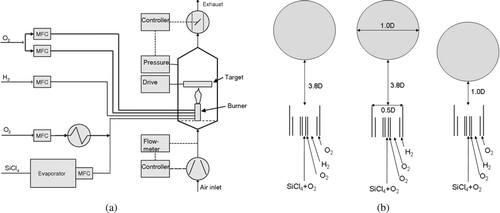
For all experiments a quartz glass burner consisting of four coaxially aligned ring nozzles was used. The origin was in the center of the rings and in streamwise position at the exit of the ring gas flows (rather than at the edges of the outer most ring). Three different flame structures were studied () to investigate the influence of the details of the flow on the resulting deposition efficiencies. In flame 1a the gas species provided to the different nozzles are as follows: innermost nozzle–silicon tetrachloride and oxygen; second nozzle–oxygen; third nozzle–hydrogen; outermost nozzle–oxygen. The areas of these ring-openings have the ratios 1:1.5:30:2 and the average gas injection velocities are summarized in . A sketch is shown in , where D denotes the diameter of the target and D/2 was the outer diameter of the burner. The Reynolds number based on the diameter of the cylinder was of the order 15,000. To study the effect of burner displacement transverse to the target rotational axis, for flame 1b the burner was shifted out off center by a distance of D/5 while keeping all other flow parameters.
TABLE 1 Gas inlet velocities in m/s for the different flames
Two additional flame configurations were studied and are shown schematically in and the flow rates are given in . For the second flame the outer oxygen was exchanged against the hydrogen and will be named flame2 throughout the present text. For flame3, the different species were injected as for the first one, however the flow rates (see ) and the distance from burner to target was reduced to 1.0D.
2.2. Flow Velocity Measurements by Particle Image Velocimetry
The gas velocities in the flame where measured for different configurations by particle image velocimetry (PIV). This technique illuminates small particles in the flow and records two images with a fixed time delay and from the displacement of the particles the velocity can be derived, for details see the textbook by CitationRaffel et al. (1998). Fifty images were averaged to obtain the mean velocities in the flame.
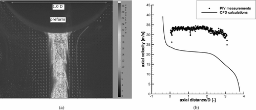
In the raw pictures it could be seen that the particles produced in the flame only existed in a small cylindrical area with a diameter of about D/5 in the center of the flame (see ). To get velocity data also for the outer regions of the flame, the gas flow through the outermost burner nozzle was additionally seeded with SiO2 particles (Aerosil 200). Hollow glass spheres (mean size 5 μ m supplied by LAVISION) also were tested as seeding particles, however they could not be detected properly, probably because they evaporated.
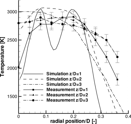
FIG. 3 Radial temperature profiles for different distances from the exit of the burner for flame 1a. Measured values are from CitationMüller et al. (2003) and calculation from .
2.3. Temperature Measurements by Laser Induced Fluorescence in the Flame
Measurements with Planar Laser Induced Fluorescence (PLIF) were carried out by the Institute for Physical High Technology (now Institute of Photonic Technology) in Jena, Germany. For a detailed description of the method see CitationKohse-Höinghaus (1994) and CitationRothe and Andresen (1997). There, a method was developed to measure the temperature of flames as they exist in industrial processes. For the measurements of the temperature distribution by Laser induced Fluorescence (LIF) no SiCl4 precursor could be used, since the nucleating particles influenced the measurements. Therefore, the Silicon tetrachloride was replaced by the same volume flow of Nitrogen.
The burner was moved in height, driven by a stepper motor, to measure throughout the whole flame. The images where taken synchronously between the movement steps and afterwards superposed and averaged by image processing. Details can be found in CitationMüller et al. (2003).
2.4. Target Temperature Measurements
A pyrometer IMPAC infratherm IN5+ was used to measure the surface temperature of the cylinder. It was found that the temperature of the alumina cylinder was around 1300 K and the nitrogen injection reduced this temperature by around 150 K. This reduction could not be found after deposition of the SiO2 particles, maybe due to the much smaller thermal conductivity of the deposited porous soot layer.
2.5. Measurements of Deposition Efficiencies
The deposition efficiencies were measured by weighing the cylindrical target after a stable soot body had formed. At that stage the deposited layer was around 10-mm thick. The deposition efficiency is defined as that part of the silica particles produced in the flame and deposited on the target. The totally generated amount of SiO2 was obtained from the measured Silicon tetrachloride flow.
3. COMPUTATIONAL FLUID DYNAMICS MODEL
The flow was calculated on a structured grid with around 130,000 control volumes using the finite volume CFD software FASTEST4.0. The symmetry of the configuration was used so that only a quarter of the flow domain had to be calculated. At the inlet, the velocities for the concentric rings were specified as provided in and a spatially constant flow around the burner with 1 m/s in the main flow direction. At the top end of the glass cylinders, comprising the rings between the flow openings, the inlet velocity was set to zero. The turbulence intensities were set to 5% of the local mean injection velocity and the turbulent lengthscale was chosen 1 mm for the two inner nozzles and 4 and 3 mm for the outer rings, respectively. However, preliminary tests showed that the inlet turbulence had little influence, since the jet like shear flow was dominant. The outlet was modeled by a gradient free boundary condition.
The standard k-ϵ turbulence model was used together with wall functions, since close to the wall the flow gradients become large and are difficult to resolve by the numerical grid. Additionally, the turbulent velocity fluctuations become non-isotropic and the Reynolds number decreases towards the wall. Both of these effects increase uncertainties when the standard k-ϵ model would be used. Therefore, wall functions are applied, which describe the velocity profiles in the last computational cell based on the logarithmic law of the wall for the turbulent part and linearly for the viscous sub-layer. The grid resolution was set to D/100 at the surface of the cylinder which corresponded to a non-dimensional wall distance of 15. More details on wall functions can be found in the book by CitationPope (2000).
Combustion was assumed to be infinitely fast and calculated using a chemistry table, which related chemical composition with thermodynamic properties of the flow. Therefore, transport equations for mixture fraction and its variance were solved. For a detailed description of the combustion model see Warnatz et al. (Citation1996, p. 179). Additionally, a transport equation for nitrogen was solved and the amount of nitrogen in the flame was taken into account by the combustion model. Nitrogen was contained in the outer air flow around the burner but not in the pure oxygen supplied to the burner. Initial tests showed that assuming the surrounding air as pure oxygen led to relevant temperature changes at the edge of the flame but not in the center of the flame. The central nozzle carried 30% oxygen plus the precursor, however the complicated reaction of SiCl4 has not been modeled and this part of the volume flux was replaced by nitrogen. The main reason for neglecting this reaction mechanism was its complexity and related uncertainties, see CitationMoore et al. (2006).
To simulate the particle deposition process the Lagrangian approach (code module LAG3D) was used, see CitationCrowe et al. (1977). Spherical particles were tracked through the turbulent flow field considering aerodynamic drag force, gravity and also the Cunningham correction, since the mean free path of the gas molecules and the particle size have the same order of magnitude. The standard formulation of CitationSchiller and Naumann (1933) was used to relate the drag coefficient with the particle Reynolds number. Usually a non-dimensional Stokes number, defined as the ratio of particle relaxation time and the turbulent time scale of the carrier fluid, is introduced in dispersed phase flows. This seems not to be necessary for the current particles, since they perfectly follow the gas flow under atmospheric conditions due to their small size. Varying the particle size does not influence turbulent dispersion as the main mechanism governing the particle distribution in the flame and the deposition on the cylinder, since the particles are very small and hence follow all velocity fluctuations of the carrier gas. The real particles are agglomerates rather than spheres, but this also does not have a relevant influence on dispersion. Therefore, a change of particle size due to reaction of the precursor and phase change has not been considered and a fixed particle size of 120 nm was used. This was obtained as an average size from Transmission Electron Microscopy images of thermophoretically sampled particles.
The particles were injected at a distance D/5 above the burner exit concentrically in a ring with outer and inner diameters D/24 and D/50, respectively. The reason for not injecting the particles in the center nozzle was that laser light sheet imaging showed, that the particles were created in an annular zone just above the burner. This is the reaction zone where the temperatures are large due to the hydrogen combustion and also a sufficient amount of SiCl4 is present. The different mass distribution of SiCl4 gas, which was in the center, and of the SiO2 particles, which were present in this annular region, may result from the small molecular diffusion of the SiCl4 gas and of the nano-particles. Hence, preliminary tests showed that Brownian motion was negligible for particle dispersion and, therefore, was not modeled. However, close to the surface the thermophoretic force could be important for the deposition mechanism and hence was considered in the calculations. Since the combustion model did not solve a transport equation for the temperature, which was based on the mixture fraction and its variance, it was not possible to predict the temperature in the boundary layer close to the cylinder. Hence, for the calculations of the particle trajectories it was assumed that in the last computational cell the temperature gradient was linear and the surface temperature was obtained from measurements as 1300 K.
A stochastic Langevin equation approach was used to model the influence of the turbulent velocity fluctuations of the carrier gas on the particles. The detailed equations of the model can be found in CitationMelheim et al. (2005) or in CitationSommerfeld et al. (1993). It should be noted that there are more advanced models to simulate turbulent velocity fluctuations stochastically, e.g., CitationMinier and Peirano (2001), which, however, use the gradients of the turbulent Reynolds stresses of the fluid. Their estimation would have introduced further uncertainties, therefore those models have not been applied for the flame deposition process yet.
The influence of the particles on the gas flow was neglected, since the total mass flux of the particles was only 15% of the mass flux of the combustion gases.
4. EXPERIMENTAL RESULTS
4.1. Flame Temperature
shows measured horizontal temperature profiles taken at different heights above the burner as presented by CitationMüller et al. (2003) together with calculated values. This comparison will be used as validation for the flow calculations and will be discussed in section 5.2. In the lower part of the flame up to 3.0D the reaction zone of oxygen and hydrogen can be seen as high temperature area, while on the center line of the flame the large flow rate of nitrogen gas, which replaced the silicon tetrachloride, cooled the flame. Due to mixing, the temperature profile became more flat with streamwise development. In CitationMüller et al. (2003) it was shown that the choice of the gas which replaced the SiCl4 in the center nozzle had a relevant influence on the temperature distribution. The temperature showed a local minimum on the center line, which existed up to 5.0D for Ar as carrier gas, up to 4.0D for N2 as carrier gas and only up to around 1.0D for He as carrier gas. This trend was explained by the reduced molecular weight and hence reduced heat capacity and increased thermal conductivity of the gasses.
4.2. Flame Velocities
A vector plot of the velocities measured by particle image velocimetry together with an instantaneous image of the flame is shown in for the area close to the target which is of particular importance for the deposition. It should be noted that the PIV measurements were performed during the continuous deposition of particles, hence the preform had already grown to a diameter of approximately 1.8D, as can be seen in the figure. Therefore, the distance between the burner and the surface of the target was slightly reduced during the measurement. Hence, there may by some influence on the flame velocities just below the cylinder due to its larger size. The central area, where most of the particles produced in the flame were present, can clearly be seen as bright regions. Additionally, at the edges of the particle jet the influence of the coherent structures in the turbulent gas jet are visible. This led to a typical mushroom like structure of the particle concentration distribution due to entrainment of pure gas.
In measured and simulated streamwise velocities on the centre line as a function of height above the burner are shown. Their comparison will be discussed in section 5.2. It should be noted that the PIV system could only measure above the outer ring of the burner (z = 0), since the reflections at the glass of the burner were strong so that no seeding could be detected behind the glass of the burner. The measurements show that the streamwise velocity had nearly constant values of 33 m/s up to streamwise position 2.0D and for larger distances the streamwise velocity decreased approximately linearly to 30 m/s at z = 2.8D. The surface of the target was at around z = 3.4D and measurements could be performed up to 3.2D, since closer to the surface no optical access was possible.
4.3. Deposition Efficiencies
The measured deposition efficiencies are summarized in for the three flame configurations and flame 2 had reduced deposition efficiencies while flame 3 had increased efficiencies compared to flame 1a. The out off center flame 1b with the burner shifted by D/5 had an efficiency reduced from 49% to 44% compared to flame 1a. This was a much smaller effect compared to the laminar flame of CitationBautista et al. (1990), who found efficiency reduced from 50% to 10% for the burner shifted by D/10.
TABLE 2 Comparison of measured and predicted deposition efficiencies
Cooling of the target with liquid nitrogen did not increase the deposition efficiencies, although the surface temperature of the aluminum oxide cylinder was reduced by around 150 K. This reduction in temperature should enhance the deposition efficiency by around 10% due to increased thermophoretic deposition, according to the data by CitationBautista et al. (1990). The reason could have been that the surface temperature was not reduced significantly after the SiO2 particles were deposited due to insulation because of the smaller thermal conductivity of this porous layer compared to aluminum oxide. Additionally, the current flame was turbulent and, therefore, the influence of thermophoretic deposition may be less important as will be discussed below.
5. NUMERIC RESULTS
5.1. Flame Structure
shows the predicted flame temperatures for the three flames (a) along a centered surface perpendicular to the cylinder axis and (b) parallel to the cylinder axis. It should be noted that only one half of the burner is shown, since the calculations used the symmetry of the set-up. All three flames show maximum temperatures of around 3000 K, which is approximately the adiabatic limit for pure hydrogen/oxygen flames. For flame 1a, large temperatures in both reaction zones of the H2 injection can be observed together with a minimum of the temperature in the center of the flame, which existed up to around 2.0D downstream of the burner. The reaction zone of flame 2 became wider due to the injection of H2 in the outer ring of the burner. Hence, a fraction of the hydrogen reacted with the oxygen of the surrounding air containing 80% nitrogen, which led to an approximately 200 K smaller temperature at the outer edge of the reaction zone. For flame 2 it could be observed that the local minimum of temperature existed until the flame reached the target. The same was observed for flame 3. The temperature distribution along the cylinder (see ), was broader for flames 2 and 3 compared to flame 1a.
FIG. 4 Planar (a) and perpendicular (b) plots of calculated streamwise velocities for flames 1a, 2, and 3 from left to right.
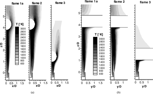
shows the predicted gas velocities for the three different flames (a) along a centered surface perpendicular to the cylinder axis and (b) parallel to the cylinder axis. For flame 2 the inlet velocities were smaller, hence the velocities were smaller in the flame compared to the flame 1a. For all flames the streamwise velocity increased at radial positions larger than zero due to the reaction. The strongest radial velocity gradients existed for flame 1a while flame 3 showed a maximum of the streamwise velocity at position 0.1D away from the center line. For the plots perpendicular to the target (), all the flames showed an increasing width with streamwise development. For the parallel plots this behavior could only be seen for flame 1a, while flame 2 showed a decreasing width for streamwise positions larger z = 2.0D. Flame 3 did not show a remarkable growth of the width with streamwise development due the short distance to the target.
FIG. 5 (a) Instantaneous image of the particle-laden flow with additional seeding and processed velocity vectors for flame 1a. (b) Measured and calculated streamwise mean velocity on the centre line as a function of streamwise position.
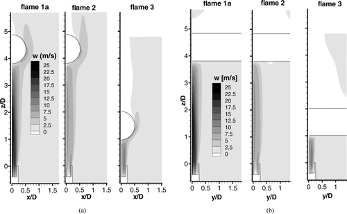
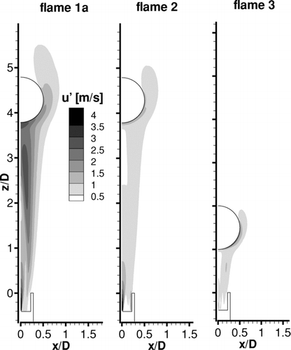
shows the turbulent fluctuating velocity for the different flames on a plane perpendicular to the target. Flame 1a showed large turbulent velocity fluctuations at the edges of the SiCl4 nozzle due to the large velocity gradients of the inflow. Additionally, turbulent velocity fluctuations started to build up for downstream positions larger z = 1.0D, with a maximum at radial positions around 0.1D away from the centre line, which is typical for free jets. In the vicinity of the cylinder the turbulence level also was increased due to the mean velocity gradients in the boundary layer. Flame 2 showed similar turbulence levels at the burner exit as flame 1a, but was nearly laminar for larger streamwise distances. Close to the cylinder surface an increase of turbulent velocity fluctuations could be observed due to the mean velocity gradients in the boundary layer, but they were approximately 50% smaller than for flame 1a. Flame 3 was nearly laminar at the burner exit due to the smaller inlet velocities but showed a similar turbulence structure as flame 2 in the boundary layer of the cylinder.
5.2. Comparison of Measured and Modeled Flame Structure
The purpose of this section is to assess the quality of the flow simulations by comparing the obtained temperature and velocity characteristics with measurements. Therefore, from the above presented simulations of flame 1a, cross-stream profiles of the temperature were extracted and are presented in . Additionally, the streamwise velocity on the center line was extracted and is presented in together with the same data from the PIV measurements. It should be again emphasized that the temperature measurements could only be performed without the Silicon precursor while the velocity measurements included the precursor.
shows that the absolute temperatures were predicted within 10% of the measurements and the shape of the profiles agreed well. Especially the development of the minimum of the temperature on the center line was captured by the simulations. Some differences remained in the width of the profiles, which were approximately 20% smaller for the simulations compared to the experiments. This may be attributed to the uncertainties related with the k-ϵ turbulence model. The second local minimum of temperature at radial position 0.14D for the smallest streamwise position could hardly be seen in the measurements. The reason for that may have been the limited spatial resolution of the measurement technique. Additionally, turbulent velocity fluctuations of around 2 m/s existed in this region, see , which led to averaging of the temperature measurement.
shows that the predicted streamwise velocities along the centre line were lower compared to the measurements by around 30% for all streamwise positions. No measurements could be obtained within the glass tubes of the burner, hence the PIV measurements start at positions z = 0. It can be seen that measured and simulated velocities remained nearly constant between z = 0.4D and z = 2.0D. This was due to chemical reaction, which led to thermal expansion and increased velocities. For positions larger z = 2.0D the streamwise velocity on the center line became smaller with streamwise development, which is the behavior of non-reacting jets. Hence, it can be concluded that the reaction was complete after about z = 2.0D. The fast drop directly at the exit of the burner in the simulations was due to fast mixing of the inner jet consisting of 70% nitrogen (instead of SiCl4) and 30% oxygen, which was injected with 38.5 m/s. This was much faster than the injection velocity of the other gases, see . Since N2 instead of SiCl4 was used in the simulations, this inner jet diffused faster than for the measurements due to the smaller molecular weight and hence larger diffusivity. Hence, the reason for the under-prediction of streamwise velocities could be that the calculations did not take into account the large mass flux of SiCl4, which was injected with a larger velocity than the other gases. However, the mass loadings of particles may not have an important influence on the spreading rate, since measurements in a mixing layer with different density streams (see CitationBrown and Roshko 1974), did not show significant changes in spreading rates for gases with density ranges 1:7. Measurements for particle-laden turbulent jets by CitationFan et al. (1992) showed that particle mass loadings of 0.5 and 10.0 reduced the width of a jet, compared to the clean gas jet, by approximately 5% and 15%, respectively.
Generally, an uncertainty in the measured velocities exists, since in the inner area of the flame structures of the produced particles existed (). Hence, single tracer particles could not be detected in this area due to the bright radiation of the produced particles. Therefore, the PIV technique measured velocities by tracking particle structures rather than single tracer particles, which could lead to errors in the processing if, for example, these structures rotated. Additionally, those visible particle clusters may have changed the turbulence structure of the flow due to locally high mass loading, which is correlated with the vortex structures.
It can be concluded that the model captured well the temperature distribution of flame 1a and also the trends of the streamwise velocity, but some uncertainties remained in the predicted velocities due to turbulence modeling and inaccuracies in the applied measurement technique.
5.3. Discussion of Deposition Efficiencies
summarizes the measured and predicted deposition efficiencies. The measured trends for the three flames were captured well by the simulations, and it should be noted that flame 1b has not been calculated, due to the lack of symmetry. Generally the deposition rates were predicted too low and the measured values were larger by a factor of approximately 1.2. A reason for that could have been that the influence of the particle mass loading on the gas flow and the consequent flame structure had been neglected. For a laminar hot flow impinging on an axisymmetric stagnation point, Rosner and Park (Citation1988; Figure 11) presented an analysis which related the particle loading to the deposition efficiency. They derived that a particle mass loading of 0.15, corresponding to the current flame, resulted in an increase of deposition efficiency by a factor of 1.2 compared to the dilute limit (mass loading zero). Although the current flame was turbulent, their analysis indicates well the magnitude by how much the deposition efficiency could be under-predicted by the present model. An additional uncertainty in the measured deposition efficiencies was related to the target growing from D to around 1.2D, which increased the deposition efficiency. This increase was not simulated.
5.4. Discussion of Deposition Locations
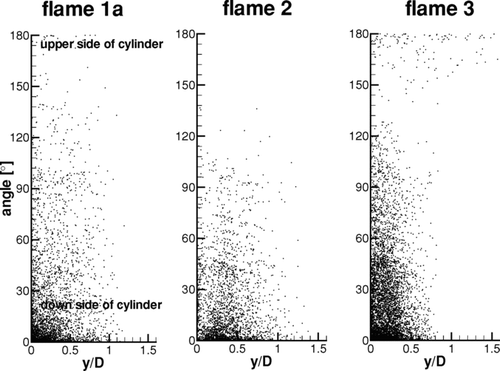
shows the locations of deposited particles as dots on the surface of the cylinder in a cylindrical coordinate system for the three flames. The angle 0° denotes the lower side, directly at the stagnation point of the cylinder and the lateral distance y = 0 denotes the centre of the configuration. The angle 180° denotes the upper side of the cylinder on the downstream side. It can be seen that for flames 1a and 2 a significant number of particles was deposited close to the stagnation point for angles smaller than around 20°, but some differences exist for the maximum angle of particle deposition. For flame 1a only a small fraction of particles was deposited for angles larger than 30°, but a few particles hit the cylinder for angles even larger than 90° up to 180° in the recirculation zone behind the cylinder. For flame 2 nearly no particles deposited for angles larger than 120° and no particles were present at the backside of the cylinder near 180°. For the lateral position of deposition for flame 1a it could be observed that the particles deposited mainly in the center position with maximum lateral deposition of y = 0.4D. For flame 2 the particles were mostly deposited between lateral position y = 0.2D and 0.6D. For flame 3 the location where most of the particles were deposited extended to an angle of approximately 60°, but there were some particles present at larger angles. A slightly increased number of particles deposited around 180°. The lateral position of main particle deposition was between y = 0 and 0.4D.
The observed trends for the deposition locations can be explained by the velocity and turbulence structure of the flames. shows that flame 1a had the largest turbulence levels close to the cylinder surface and also the boundary layer was thicker compared to the other flames. Therefore, the particles were transported towards the surface of the cylinder from a greater thickness compared to flame 2. Hence, particles which were further away from the cylinder touched the surface at a larger height and such particles would miss the cylinder for flame 2. This may have contributed to the smaller deposition efficiency of flame 2. The fact that the major deposition did not happen for lateral position y = 0 also may be attributed to the smaller turbulence levels, which were not large enough to disperse the ring shaped particle concentration distribution towards the center of the flame.
For flame 3, the turbulence levels close to the cylinder were as low as for flame 2 and the mean gas velocities were similar (see ). However, the turbulence levels close to the burner exit were nearly zero for flame 3 and together with the smaller distance, which the particles had to travel, this led to a narrow distribution of the particle concentration. Therefore, more particles hit the cylinder.
5.5. Discussion of the Role of Thermophoresis and Turbulence
Many studies emphasized thermophoresis as dominant mechanism for particle deposition (e.g., CitationBautista et al. 1990; CitationGraham & Alam 1991; CitationTandon et al. 2005). However, all of these experimental, analytical, and numerical studies were performed for laminar flames only. In a turbulent boundary layer the temperature and velocity gradients are much steeper and located in a thinner region around the cylinder compared to the laminar case, see for example Pope (Citation2000, p. 310). Hence, thermophoresis can only create a drift towards the colder surface in a very thin layer. In this layer, turbulent velocity fluctuations of the carrier gas additionally transport the particles towards the surface; however, this mechanisms extends deeper into the flow perpendicularly to the surface. Therefore, particles further away from the cylinder are also transported towards the surface by turbulence. Hence, it may be suggested that for turbulent flames thermophoresis may have a small influence on the deposition compared to turbulent transport. In the following paragraphs some further calculations together with data from the literature will be presented to support this conclusion.
shows the predicted deposition efficiencies with and without considering the thermophoretic force for the three investigated set-ups. Surprisingly, the deposition was even slightly reduced for the case with thermophoresis, e.g., for flame 1a from around 0.39 to 0.35. An explanation for this reduction of deposition efficiency could be the detailed structure of the flame. Thermophoresis could lead to a broader particle distribution above the burner, since there was a relevant amount of particles present in the area where large temperature gradients exist and would move the particles away from the center line. This may have had a larger influence on the total deposition efficiency than the increased deposition due to temperature gradient close to the surface of the target. Hence, more particles missed the flame when the thermophoretic force was applied in the current model.
To further investigate the role of turbulence, in the current simulations the turbulent dispersion model and thermophoresis were switched off so that only the mean velocities in the flame were acting on the particles. The deposition efficiency decreased from around 0.39 to around 0.12 for flame 1a and to 0.16 for flame 3, respectively. These small deposition efficiencies for the laminar case are consistent with the numerical study of Wu and Greif (1996), who also predicted such too low deposition efficiencies.
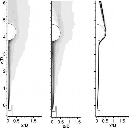
shows the particle concentration in flame 1a in arbitrary units for turbulent tracking, turbulent tracking with thermophoresis and laminar tracking (from left to right). The case with thermophoresis (middle) did not show any significant differences to the case without thermophoresis (left). The laminar case (right) showed large differences and the particles were not dispersed significantly, therefore most of them missed the cylinder. It should be noted that this is not a correct simulation of a laminar flame, since then the boundary layer would have been also laminar and hence thicker, so that thermophoresis could bring the particles towards the surface from a thicker layer. For the simulations shown in , the injection of particles was realized in a ring with inner and outer radius D/50 and D/24 and this non-central injection, which closely matches the experimental observations, led to a low deposition efficiency of around 0.12 for the laminar tracking and to 0.39 for the turbulent tracking (see ). An additional test was made for flame 1a with central injection in a circle with radius D/50 and this led to deposition efficiencies of 0.46 for laminar tracking and 0.42 for turbulent tracking. This implies that particles which were injected off-center are more likely to miss the cylinder for laminar flames, which was also found by CitationBautista et al. (1990). They observed that an out off centre injection of D/20 reduced the deposition efficiency significantly from around 0.5 to 0.2. Comparing this with the off-axis arrangement of flame 1b, where the off-axis distance was D/5, leading to a reduction of deposition efficiency from 0.49 to 0.44, it may be concluded that deposition from turbulent flames is far less sensitive with respect to a shift of the burner out off the axis of the cylinder.
FIG. 8 Particle concentration on the central plane perpendicular to the cylinder for flame 1a (left), with thermophoretic force (middle), and laminar tracking (right).
In summary, it can be concluded that for correct modeling of the thermophoretic deposition process, great care should be taken to investigate whether the boundary layer over the depositing surface is turbulent or not.
6. CONCLUSIONS
Measurements and numerical calculations of flame temperatures and velocities of a particle-laden flame impinging on a cylinder for the production of ultra pure glass tubes were presented. The predicted flame temperatures showed good agreement with measurements and also the trends of the predicted velocities agreed well with measurements. Some discrepancies could be explained by the fact that the inner nozzle carried oxygen and nitrogen in the simulations while the experiments for the velocity measurements used the real condition with SiCl4 injection through the inner nozzle, which contributed a considerable amount of momentum to the flame leading to larger velocities. Hence, the simulations of the flame were validated successfully and the main findings regarding the deposition process modeled by Lagrangian particle tracking are as follows:
| a. | Particle deposition efficiencies were predicted within ± 10% of the measured values and the modeled trends for three different flames were correct. | ||||
| b. | The general trend was that the deposition efficiency was under-predicted by up to 10%, which may be due to neglecting the effect of particle mass loading. | ||||
| c. | Deposition positions of the particles on the cylindrical target were presented. The positions showed differences for the three flame configurations, which could be explained by the velocity and turbulence characteristics of the flames. | ||||
| d. | The main deposition mechanism for the current manufacturing process is turbulence, since in the current turbulent flame thermophoresis had not a relevant influence, as was demonstrated by simulations and experiments. | ||||
| e. | Off-axis injection of the particles was found to have less influence on the deposition from turbulent flames compared to laminar flames. | ||||
Acknowledgments
The authors would like to thank Dr. Sadiki and Prof. Schäfer from TU-Darmstadt for providing the CFD code and the combustion model and the group of Prof. Triebel from IPHT Jena for providing the results of the LIF-measurements. The work was funded by Heraeus Tenevo GmbH.
REFERENCES
- Bautista , J. R. , Walker , K. L. and Atkins , R. M. 1990 . Modeling Heat and Mass Transfer in Optical Waveguide Manufacture . Chemical Engineering Process , : 47 – 52 .
- Brown , G. L. and Roshko , A. 1974 . Density Effects and Large Structure in Turbulent Mixing Layers . J. Fluid Mech. , 64 ( 4 ) : 775 – 816 .
- Cho , J. , Kim , J. and Choi , M. 1998 . An Experimental Study of Heat Transfer and Particle Deposition During the Outside Vapor Deposition Process . Int. J. Heat Mass Transfer , 41 : 435 – 445 .
- Crowe , C. T. , Sharma , M. P. and Stock , D. E. 1977 . The Particle-Source-in-Cell (Psi-Cell) Model for Gas-Droplet Flows . J. Fluids Engineering , 99 : 325 – 332 .
- Fan , J. , Zhao , H. and Cen , K. 1992 . An Experimental Study of Two-Phase Turbulent Coaxial Jets . Exp. Fluids , 13 : 279 – 287 .
- Graham , G. M. and Alam , K. M. 1991 . Experimental Study of the Outside Vapor Deposition Process . Aerosol Sci. Technol. , 15 : 69 – 76 .
- Hong , K.-H. and Kang , S.-H. 1998 . Three-Dimensional Analysis of Heat Transfer and Thermophoretic Particle Deposition in OVD Process . Int. J. Heat Mass Transfer , 41 : 1339 – 1346 .
- Kohse-Höinghaus , K. 1994 . Laser Techniques for the Quantitative Detection of Reactive Intermediates in Combustion Systems . Prog. Energy Combust. Sci. , 20 : 203 – 279 .
- Li , T. , ed. 1985 . Optical Fiber Communication , New York : Academic Press .
- Melheim , J. A. , Horender , S. and Sommerfeld , M. 2005 . Modeling of the Vortex Structure in a Particle-Laden Mixing Layer FEDSM2005-77040
- Minier , J.-P. and Peirano , E. 2001 . The pdf Approach to Turbulent Polydispersed Two-Phase Flows . Physics Reports , 352 : 1 – 214 .
- Moore , T. , Brady , B. and Martin , R. 2006 . Measurements and Modeling of SiCl4 Combustion in a Low-Pressure H2/O2 Flame . Combustion and Flame , 46 : 407 – 418 .
- Müller , D. , Triebel , W. , Bochmann , A. , Schmidl , G. , Eckardt , D. , Burkert , A. , Röper , J. and Schwerin , M. 2003 . Two-Dimensional Concentration and Temperature Measurements in Extended Flames of Industrial Burners Using PLIF . Proc. SPIE , 5191 : 66
- Pope , S. B. 2000 . Turbulent Flows , Cambridge University Press .
- Raffel , M. , Willert , C. and Kompenhans , J. 1998 . Particle Image Velocimetry—A Practical Guide , Berlin : Springer Verlag .
- Rosner , D. E. and Park , H. M. 1988 . Thermophoretically Augmented Mass-, Momentum- and Energy-Transfer Rates in High Particle Mass Loaded Laminar Forced Convection Systems . Chem. Engineer. Sci. , 43 : 2689 – 2704 .
- Rothe , E. W. and Andresen , P. 1997 . Application of Tuneable Excimer Lasers to Combustion Diagnostics: A Review . Appl. Opt. , 36 : 3971 – 4033 .
- Schiller , L. and Naumann , A. 1933 . Über die grundlegende Berechnung bei der Schwerkraftaufbereitung . Ver. Deut. Ing. , 44 : 318 – 320 .
- Sommerfeld , M. , Kohnen , G. and Rüger , M. Some Open Questions and Inconsistencies of Lagrangian Particle Dispersion Models . In Ninth Symposium on “Turbulent Shear Flows.” .
- Tandon , P. and Balakrishnan , J. 2005 . Predicting Heat and Mass Transfer to a Growing Rotating Preform During Soot Deposition in the Outside Vapor Deposition Process . J. Chem. Engineer. Sci. , 60 : 5118 – 5128 .
- Tandon , P. , Terrell , J. P. , Fu , X. and Rovelstad , A. 2003 . Estimation of Particle Volume Fraction, Mass Fraction and Number Density in Thermophoretic Deposition Systems . Int. J. Heat Mass Transfer , 46 : 3201 – 3209 .
- Tsai , H. C. , Greif , R. and Joh , S. 1995 . A Study of Thermophoretic Transport in a Reacting Flow with Application to External Chemical Vapor Deposition Processes . Int. J. Heat Mass Transfer , 38 : 1901 – 1910 .
- Warnatz , J. , Maas , U. and Dibble , R. W. 1996 . Combustion , Berlin-Heidelberg : Springer .
- Wu , C. K. and Greif , R. 1995 . Thermophoretic Deposition Including an Application to the Outside Vapor Deposition Process . Int. J. Heat Mass Transfer , 39 : 1429 – 1438 .
