Abstract
Thermal-optical analysis (TOA) has been widely used to separate carbonaceous aerosols from ambient and source samples into two components, organic and elemental carbon. This method uses volatility to separate groups of carbon, and laser monitoring to correct for the transformation of non-absorbing carbon into pyrolytic carbon that absorbs light. However, assumptions inherent in this method have proven incorrect, leaving interpretation of the results open to question. We present a framework for interpreting TOA results based on the optical and carbon-release signals recorded by the instrument, which accounts for co-evolution of different groups of carbon (organic carbon, light-absorbing carbon [LAC] native to the sample, and pyrolytic carbon). Optical cross-sections of carbon groups for use in this model are derived from measurements, and depend on filter transmittance for LAC but not for pyrolytic carbon. We constrain temperatures of carbon evolution by examining samples from controlled aerosol generation and model organic compounds. The system of equations describing the analyzer's response is underdetermined during portions of the analysis, with one fewer equation than needed to quantify all the evolving groups. Our model, REACTO (REAnalyzing Carbon Traces Optically) identifies the range of possible sample compositions consistent with the analyzer's output. We also demonstrate the utility of the “thermabsgram,” which identifies formation and loss of absorbing carbon by taking the derivative of the change in filter transmission.
NOMENCLATURE
| Abbreviations | ||
| EC | = |
Elemental carbon, as measured by thermal-optical analysis |
| OC | = |
Organic carbon, as measured by thermal-optical analysis |
| TOA | = |
Thermal-optical analysis |
| Variables and groups | ||
| ATN | = |
Attenuation, described by equation Equation3 |
| CARB | = |
Carbon released from the sample |
| I | = |
Intensity of light transmitted through filter |
| I 0 | = |
Intensity of light incident on filter |
| K | = |
Filter enhancement of mass absorption cross-section (unitless; depends on transmittance) |
| L n | = |
Filter loading of group n (μ g/cm2) |
| OCc | = |
Charrable organic carbon |
| OCv | = |
Volatile organic carbon |
| PC | = |
Pyrolytic carbon, the light-absorbing material generated during TOA |
| LAC | = |
Light-absorbing carbon, the desired result of thermal-optical analysis |
| σ | = |
Mass absorption cross-section of a particular group without filter enhancement (m2/g) |
| τ | = |
Transmittance compared with transmittance of blank filter (I/Iblank) |
1. INTRODUCTION
1.1. Background
Carbonaceous material is one of the major components of submicrometer aerosol particles. Among its deleterious effects are visibility degradation and climate change. Although the chemical composition of carbonaceous aerosols is complex, it is often described as two major components: light-absorbing carbon (LAC), a stable material which absorbs visible light, and organic carbon (OC), which absorbs little light at visible wavelengths.
Thermal analysis has been used to classify carbonaceous aerosols in both ambient and source samples into LAC and OC. Because thermal analysis does not yield a true value of LAC, the refractory component it measures takes a different name: elemental carbon (EC). (This has no relationship to a chemist's definition of “elemental.”) Thermal methods rely on the assumption that organic carbon is volatile, and the strongly light absorbing carbon is stable or refractory at elevated temperatures. It assumes that LAC in a sample is unchanged until exposed to both elevated temperatures and an oxidant, so that carbon driven off at low temperatures or in the absence of oxygen must be OC. Ideally, TOA would be a separation-and-detection technique similar to chromatography, but failures of separation have hampered its interpretation.
Some OC undergoes pyrolysis or charring in the absence of oxygen, forming pyrolyzed carbon (“charring”) instead of volatilizing (CitationHuntzicker et al., 1982). For that reason, the sample is also monitored optically. The sample usually becomes blacker as charring occurs in an inert atmosphere, and the blackness decreases as the pyrolyzed carbon burns later in the analysis. This change is detected by monitoring either transmittance or reflectance (sometimes both). When the filter's transmittance or reflectance returns to the original value, it is assumed that the remaining material is EC. This point is colloquially termed the OC/EC split and the combined analysis is known as thermal-optical analysis (TOA).
Investigations of the thermal-optical method have examined “round-robin” tests of different protocols, or sequences of temperature and analysis environments (e.g., CitationCadle et al., 1990; CitationCountess et al., 1990; CitationSchmid et al., 2001). Studies have provided the differences between OC/EC split produced by various temperature programs (e.g., CitationChow et al., 2001; CitationSubramanian et al., 2006), and quantification of positive and negative artifacts (e.g., CitationCadle et al., 1983; Huebert and Charlson, 1996; CitationKirchstetter et al., 2001). Some examples of successful results have been agreement on measurement of total carbon (CitationSchmid et al., 2001) and reproducible measurements of EC and OC from careful and consistent application of thermal programs (CitationSchauer et al., 2003). A wide variety of temperature programs has been used in TOA, often with differing results (CitationSchmid et al., 2001; CitationWatson et al., 2005). The combination of temperature program and optical analysis best suited to analyzing different types of samples is still a subject of debate. Many papers have pointed out challenges in interpreting TOA results (CitationCadle et al., 1983; CitationReid et al., 1998; CitationChow et al., 2001; CitationConny et al., 2003; CitationSubramanian et al., 2006), and the method has both detractors and supporters.
Imperfections of the method, however, do not change the need for rigorous interpretation of the existing data set, which represents a substantial investment and which is presently being exploited in ways unforeseen by its original designers. The OC-to-EC ratio is used to infer changes in atmospheric aerosol, with larger ratios assumed to result from formation of secondary organic aerosol (e.g., CitationStrader et al., 1999; CitationLim and Turpin, 2002; CitationPolidori et al., 2006). Inverse-modeling techniques have used TOA results to infer sources of EC (e.g., CitationPark et al., 2003; CitationHakami et al., 2005). Furthermore, because TOA is widely accepted, it is being used to characterize air quality in other countries with rapidly growing air quality problems (e.g., CitationVenkataraman et al., 2002; CitationCao et al., 2003). The results of TOA will contribute to assessing air quality and long-range transport in the Northern Hemisphere far into the future. Thus, it is becoming more important to understand how TOA measurements of EC compare to absolute values of LAC, and how they might be biased for different samples.
1.2. Study Goals
The TOA response consists of time-resolved carbon release (or evolution) from a filter sample, and change in filter transmittance (blackening or lightening) in response to temperature or analysis environment changes. The sample composition may be thought of as a solution to physical equations that represent the response of that system. The conundrum of TOA lies in the fact that more than one sample composition is physically consistent with the system's response. The goal of this study is to identify all possible consistent solutions, instead of seeking reasons to favor one proposed solution over another. In this study, we rely on the real-time monitoring of the sample transmittance to provide information about the sample's behavior that has been previously unexploited. To ensure that the approach is tractable for historical data, we seek to quantify the uncertainties inherent in an individual analysis, based on the information available in the analysis alone.
In section 2, we review what is known about the response of TOA, and present the equations that describe it. These equations require additional data, and section 3 describes the samples and experiments we used to seek them. Measurements to characterize optical properties of filters and absorbing carbon on those filters are discussed in section 4, and section 5 discusses the search for additional constraints on the temperatures or reaction rates. Despite this additional information, the TOA system remains indeterminate, with more unknowns than constraining variables. We describe and implement a method that identifies solutions consistent with the analyzer's output in section 6. We conclude with an outlook and recommendations in section 7.
1.3. Definitions
Our definitions in this article follow those of CitationBond and Bergstrom (2006), who sought terms to differentiate operationally defined material from true definitions of chemical species. Throughout this paper, the term “elemental carbon” (EC) will indicate the result of thermal-optical analysis, and “light-absorbing carbon” (LAC) will refer to the strongly light-absorbing material that is present in the atmosphere. LAC is readily identifiable with electron microscopy (e.g., CitationHeckman, 1964) but has eluded analysis by thermal-optical techniques. LAC is the conserved species that should ultimately be identified, while EC is an operational definition that presently depends upon the measurement method. We do not use the term “black carbon,” which refers to material measured with optical techniques. When we discuss the mathematical analysis to determine the light-absorbing component in an aerosol sample, we will refer to LAC, because that is the material we wish to identify. However, the results of this analysis should rightfully be called “EC,” along with any other results from TOA.
We also use two definitions that are specific to thermal analysis. “Pyrolytic carbon” (PC) will describe the carbonaceous product generated during thermal analysis which absorbs light. This carbon probably does not exist on the filter as particles, but rather as fiber coatings (CitationChow et al., 2004), possibly from liquid, deposited particles (CitationSubramanian et al., 2007). While pyrolysis could also produce carbonaceous compounds that do not absorb light, literature on TOA does not usually refer to these compounds as pyrolytic carbon. Finally, the term “traditional TOA” will refer to any interpretation procedure which relies on the assumption that carbon groups evolve separately.
2. MODEL DEVELOPMENT
2.1. Accounting for Co-Evolution
Most of the analytical artifacts reported in the literature can be summarized as follows: Current interpretation does not account for co-evolution of different groups of carbon. In order to consider all evolving carbon, to propagate uncertainty, and to take advantage of the optical response, we formally represent the loaded, temperature-controlled filter as a small reactor.
Our model contains four groups of carbon: two organic carbon (OCv and OCc) and two groups that absorb light (PC and LAC). These are listed in . These groups are not individual molecular species, but rather lumped groups of compounds with distinctive behavior. The composition of each group may vary with temperature; some groups may pyrolyze at one temperature and volatilize at another. We use these groups only as a convenience to represent the behavior of aerosol in the reactor, without making any assumptions about their composition. The goal of TOA is quantifying OC (OCc + OCv) and LAC. The division of OC into two groups is for convenience in the model.
TABLE 1 Species represented in the reactor model
shows the reactions that occur during thermal-optical analysis. All current methods assume that the number of reactions occurring simultaneously is limited; specifically, that only one reaction in this table causes carbon to leave the reactor (CARB) at any given time. If that assumption is correct, then the detected carbon can be assigned to one of the groups.
TABLE 2 Reactions affecting the species in . CARB is the carbon released from 4 the sample and measured by the detector
evaluates the assumption that groups evolve individually. Each column considers one combination of carrier gas and temperature, and identifies whether groups change under those conditions (definitely, sometimes, or very little). The table also shows whether the carbon exits the reactor and is detected (arrow). In each column, if only one group evolves from the reactor, the detected carbon may safely be identified. Since the difference between OCv and OCc is unimportant, the detected carbon may be identified as OC even if both evolve. However, in most of the columns, the detected carbon comes from more than one group.
TABLE 3 Conditions under which carbon species within a sample change during an analysis
also indicates (exclamation point) when the evolving groups differ from the assumptions in traditional TOA. If all the arrows associated with exclamation points were removed, then each column would be adequately constrained; only one group (or OCv + OCc) would evolve. For interpreting the table in the context of traditional TOA, the “He-Ox, Low T” column applies before the OC/EC split point, and the “He-Ox, High T” column applies after the split point (even if the split occurs at a relatively low temperature).
Previous literature has amply demonstrated failures in the assumptions of traditional TOA. PC or LAC can evolve even in “He, High T” (CitationChow et al., 2001; CitationConny et al., 2003; CitationSubramanian et al., 2006), especially if metal oxides are present (CitationNovakov and Corrigan, 1995; CitationMartins et al., 1998; CitationChow et al., 2001). In “He-Ox, Low T,” OCv can fail to volatilize during the inert step if it is too heavy, so it is released only upon introduction of oxidizer (CitationSchauer et al., 2003; CitationSubramanian et al., 2006). In both “He-Ox” columns, both PC and LAC can be oxidized at the same time (CitationYang and Yu, 2002; CitationChen et al., 2004; CitationSubramanian et al., 2006). The challenge of this work is to develop a framework to account for these non-ideal situations.
2.2. Carbon Loss from the Reactor
We begin the development of a physical model of TOA by stating the obvious:
Equation (Equation1) has four unknowns on the left-hand side and one measured value on the right-hand side. Three more equations are needed to determine a solution, and seeking those constraints is the goal of this article. One of these equations comes without pain. We defined OCc as only the carbon that creates PC, so:
Two more equations are needed, and the remainder of this paper explores two avenues to provide them. First, constraining equations could be added if it is certain that some groups do not change during a particular time step. For example, LAC does not evolve during the “He, Low T” step, so we could add the equation (Δ LAC = 0) during that time step. Similar constraints could be applied if the fraction of carbon evolving were known. In section 5, we seek constraints for this approach using TOA measurements of samples. Exploiting the other response of the TOA system, the measured laser signal, can also provide constraints, and we explore this possibility in the next section.
2.3. Formation and Loss of Absorbing Carbon
In traditional TOA, the measurement of the light transmitted through the filter on which light-absorbing material is deposited is used only to locate the OC/EC split point. However, it is also a real-time measurement that may contain information about the change in a filter sample. We review the presentation of light transmitted through a filter on which light-absorbing material is deposited.
Similar to CitationGundel et al. (1984), we define attenuation (ATN) based on the ratio between transmitted light (I) and incident light (I 0).
The factor of 100 is traditional, but it also accounts for a unit conversion in the following derivation. A general model of ATN for a filter laden with N groups is:
If the conditions change, the difference in ATN is
In the equation above, the dependence on filter transmittance is omitted for brevity. However, it should not be forgotten. We obtain values of Δ ATN filt and K(τ) σ from measured data in Sections 4.1 and 4.2, respectively. As we will show, Kσ is a strong function of τ for LAC particles.
2.4. Aside: The Use of Thermabsgrams
A traditional OC/EC analysis produces a “thermogram”: a graph of carbon release versus time (CARB). Dividing Δ ATN by the appropriate value of Kσ provides an estimate of absorbing carbon formed or lost, and adding this time series to this graph conveys information on the changing optics. We call the resulting figure a “thermabsgram,” and provide three examples in . Thermabsgrams are visual, not quantitative, tools for interpreting TOA response that rely on the discussion in the previous section.
FIG. 1 Thermabsgrams for diesel exhaust aerosol (top), smoldering wood (center), and fulvic acid (bottom). Vertical line marks a change from helium to helium-oxygen atmosphere. (Figure provided in color online.)
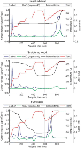
The value of (Δ ATN/Kσ) is only a proxy for light-absorbing carbon. In keeping with the CARB signal, a negative value of Δ ATN/Kσ indicates formation of light-absorbing carbon; a positive value indicates release. Any analysis that uses an optical trace to calculate the OC/EC split point inherently assumes that the analyzer's optical and CARB responses are related on a second-by-second basis, and we continue that assumption here.
We will discuss quantitative interpretation of optical changes in the remainder of this paper. We begin with this qualitative discussion to demonstrate how the Δ ATN/Kσ signal provides information about the sample and its response to the analyzer. The reader will naturally have questions about the values assumed for Kσ, which are critical to this interpretation; these are discussed in the sections immediately following. We use a constant, transmittance-independent value of Kσ (45 m2/g) to calculate Δ ATN/Kσ in . As we will show later, this is a reasonable value for PC, and too high for LAC. We have found that estimating transmittance-dependent Kσ in the thermabsgram hampers the user's understanding.
For both diesel exhaust () and hexane soot, there is very little change in Δ ATN/Kσ under the inert atmosphere, indicating a lack of charring. Δ ATN/Kσ is lost from the filter at the same time as carbon. Although these observations could be gleaned from the undifferentiated laser signal, Δ ATN/Kσ demonstrates the location of the peak. It is much lower than the CARB signal in this sample, because Kσ for the material originally present on the filter is lower than 45 m2/g. The Δ ATN/Kσ and CARB responses are not precisely proportional in this case because Kσ varies with transmission, as discussed in section 4.2.
Flaming was not permitted during the generation of the smoldering wood sample, so no LAC was present on the filter. Charring is evident from the change in Δ ATN/Kσ, which occurs mainly during the fourth temperature step in the inert atmosphere. After oxygen is introduced, only PC is lost, and Δ ATN/Kσ agrees exactly with CARB. In this case, the value of Kσ is correct and appropriate and constant throughout the analysis.
The fulvic acid thermabsgram has some complicating features. This sample begins with no light-absorbing carbon; the initial and final transmittances are quite close. In the inert atmosphere, formation of PC is evident in Δ ATN/Kσ. The shape of these formation peaks is similar to that of the CARB peaks, and formation occurs at lower temperatures than in the wood smoke sample. Evolution of heavy organic carbon continues throughout the inert-atmosphere period and is incomplete at the end. This material evolving in the final step of the inert atmosphere is not PC, because there is no change in Δ ATN/Kσ . After oxygen is introduced, both heavy organic carbon and PC oxidize rapidly.
In the fulvic acid sample, the difference between the two signals after oxidizer is introduced results from the evolution of heavy, nonabsorbing OC. For both diesel exhaust and fulvic acid samples, the CARB and Δ ATN/Kσ signals differ after oxygen is introduced. However, the apparently similar responses have completely different causes.
In summary, adding a proxy for absorbing carbon, resulting in a thermabsgram, can identify when charring occurs, when absorbing carbon is lost, and whether evolving carbon could be OC or some type of absorbing carbon (within limits). Although the thermabsgram is not a quantitative tool because an arbitrary value of Kσ is used, we have found it to be a very useful qualitative tool.
3. EXPERIMENTAL METHODS
In this section, we describe generation and analysis of samples that provide data for the equations developed in section 2.
3.1. Sample Generation
In this study, we chose not to examine ambient aerosol because it results from a complex mix of sources, and mechanisms and parameters for such a mixture would be difficult to attribute to individual components. Our compromise was examining combustion aerosol generated by single sources. Such aerosol would have fewer components than ambient samples, but would still be a realistic constituent of ambient aerosol. Conclusions drawn using individual aerosol components have an important, but limited place. Optical properties for individual components can be obtained only from studies on unmixed aerosol. Also, demonstration of assumptions made in traditional TOA on these simplified samples is a necessary, but not a sufficient, condition that those assumptions are valid for ambient aerosol. If those assumptions prove false for simple samples, they are likely invalid for mixed samples as well.
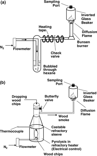
Particles were generated with a diffusion flame from a hexane-nitrogen mix and from wood chips burned at controlled temperatures. We chose hexane because soot from hexane burning has also been characterized extensively as a reference material (e.g., CitationAkhter et al., 1985a, Citation1985b; CitationSmith et al., 1995). We examined wood combustion emissions because they are a large contributor to atmospheric carbonaceous aerosol. For this source, we generated both light absorbing carbon by flaming combustion of wood and organic aerosol produced by devolatilization. Schematics of the generators that provide carbonaceous particles from wood burning and hexane are shown in and 2b, respectively.
In addition to laboratory-generated aerosol, we analyzed model compounds: humic acid (Fluka, Sigma-Aldrich), Suwanee River humic acid (International Humic Substance Society), and sucrose (Sigma-Aldrich, also used for calibrations). We dissolved each compound in water and pipetted the filtered solution onto a baked quartz filter punch, dispensing it evenly to ensure uniform light absorption if charring occurred. Spike volumes ranged from 30–100 μ L. Each punch was covered with aluminum foil to prevent contamination, and dried for a minimum of 12 h. While these compounds are introduced to the filters as liquid instead of as aerosol, many organic compounds behave as liquids when collected on fibrous filters (CitationSubramanian et al., 2007).
Finally, we analyzed samples from diesel vehicles in Bangkok, Thailand (CitationOanh et al., 2008; CitationSubramanian et al., 2008). Briefly, filters for collection were baked at 550°C, stored in foil-lined Petri dishes wrapped with Teflon tape, and shipped to the sampling location on blue ice. Heavy-duty and light-duty diesel vehicles were tested on chassis dynamometers in the Bangkok Pollution Control Division facility.
3.2. Thermal-Optical Analyzer
We analyzed samples with a Sunset OC/EC analyzer. Like other common thermal-optical instruments, this analyzer reports filter carbon loading in micrograms per square centimeter (μ g/cm2), and we will follow this convention. The instrument executes a calibration after each sample analysis by injecting a known quantity of 5% methane in helium gas, and this calibration is used to adjust the response of the flame ionization detector. We calibrated the instrument regularly with known quantities of sucrose pipetted onto filters. Daily quality control included at least two instrument blanks and a “three-peak” calibration in which the amount injected for calibration is also measured under helium and helium-oxygen atmospheres.
For most of the work presented here, we used either the standard heating program provided by the manufacturer (Sunset), or the standard program modified to include a longer residence time at each temperature step, which allows for better resolution of each peak. This program is listed in . The temperatures in this program are similar to those used by CitationSchauer et al. (2003) and the Pittsburgh Supersite (CitationSubramanian et al., 2006). We collected the aerosol on quartz filters (Pall QAT-UP 2500) which were pre-baked for 16 hours at 550°C.
TABLE 4 Temperature program used in this study
The OC/EC analyzer records data every second during sample analysis and calibration. These data include the amount of carbon released, the transmittance of the laser beam through the particle-laden filter, and the oven temperature. We developed computer codes in MatlabTM which read the output files directly and perform the analysis. The codes read the real-time signal of the carbon output and adjust it to the calibration peak just as the manufacturer's software does. Total carbon is usually within 0.1 μ g/cm2 of the manufacturer's result (see Supplemental Information, S2). The manufacturer's EC fraction can be reproduced using their algorithm. These codes are freely available from the authors.
4. EXPERIMENTAL VALUES FOR OPTICAL PARAMETERS
4.1. Blank Filter Transmittance
The change in attenuation of the unloaded filter (Δ ATN filt ) is small but may be non-zero. The apparent transmittance of the blank filter depends on the optical properties of the filter and, perhaps, the glass support. Temperature or other conditions in the analyzer could cause variations in these properties, and the resulting change in transmittance (Δ ATN blank in Equation [6]) could be incorrectly ascribed to chemical changes in the sample. The dependence could be caused by changes in the refractive index of the quartz fibers, because electronic transitions within a material are affected by temperature (CitationCody, 1984); it could also result from physical changes in structure of the filter or glass support, such as thermal expansion. Other potential explanations include temperature dependence of either path length or laser optics.
We characterized this dependence based on 176 blank filter analyses performed as part of routine quality control in our laboratory. This discussion is lengthy, and much of it is relegated to the Supplemental Information (S3). We consider both rapid changes in the transmittance which may occur during transitions across a specific temperature, and the apparent temperature dependence of blank filter transmittance. We tried three correction schemes, including the manufacturer's, to account for the temperature dependence. If no correction is used, the estimate of EC could be biased by about 0.27 μ g/cm2. The most successful scheme is a quadratic fit to the temperature dependence during the calibration period, although the manufacturer's scheme is almost as good. The results of the quadratic fit are used to predict Δ ATN blank for Equation (Equation6). However, Δ ATN blank is not perfectly predicted, even after the correction. When EC has a relatively low loading, the apparently small uncertainties could be significant for lightly-loaded samples. A more stable laser signal, and a better understanding of the variation with temperature, could reduce this inherent uncertainty.
4.2. Attenuation by Light-Absorbing Carbon
Likely values of Kσ for particles deposited as light absorbing carbon come from the ratio between Δ ATN and Δ L (Equation [6]) during oxidation. We use three types of samples: hexane soot, diesel exhaust, and flaming wood combustion. The values of Kσ derived here assume that only LAC is present on the filter. We eliminate samples with two confounding factors. First, non-absorbing organic carbon should not remain on the filter after the volatilization period; it would cause an underestimate of Kσ. We therefore screen out samples which have a non-zero rate of carbon release at the end of the high-temperature volatilization period. Second, pyrolytic carbon would confound the estimate of Kσ. We eliminate samples for which our estimate of PC formed during the volatilization period was greater than 5% of the total carbon release. The analysis is based on the remaining 101 samples: 28 hexane soot, 51 diesel, and 2 flaming wood.
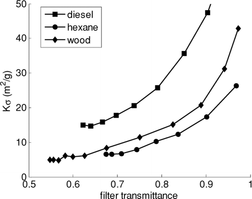
shows values of Kσ for 10 s values during the analysis of three illustrative samples. The dependence on filter transmittance is common to all samples; it has been reported previously (CitationBond et al., 1999; CitationWeingartner et al., 2003) but has not been raised in the context of TOA. Although the thermabsgram in may suggest that LAC released at lower temperatures absorbs less light, this is an artifact of the dependence on τ. Release temperature does not explain the variation in values of Kσ (p = 0.69 in a multiple regression).
FIG. 3 Absolute values of Kσ as a function of filter transmittance for three illustrative samples of LAC.
Equations of the form
We find that LAC from diesel exhaust is significantly more absorbing than that from wood and hexane combustion (p < 0.0001). This contradicts the finding of CitationBond and Bergstrom (2006) that a common value of mass absorption coefficient could explain most reported measurements. However, those authors also pointed out that LAC from many sources, including biofuel combustion, had not been investigated.
The asymptote a averages 6 ± 4 m2/g for the 101 samples, similar to the value expected for LAC at 680 nm when there is no filter enhancement. We determined a functional form for the dependence of Kσ on transmittance by fitting Equation (Equation8) to each sample and dividing by a. shows the results for all samples, as well as the mean and 1.25 standard deviations away from the mean of these 101 curves. Because of correlations between a, b and r, curves developed by simply using averages and standard deviations of the parameters did not represent all the data. Standard deviation times 1.25 bounded most of the data; one standard deviation was clearly too few and 1.96 standard deviations (usually required to bound 95% of the data) was too many.
FIG. 4 Dependence of Kσ on filter transmittance for 101 samples. Heavy lines show mean and mean ± one standard deviation. Values have been normalized to the asymptotic value of Kσ at low transmittance. (Figure provided in color online.)
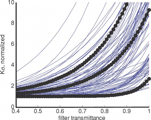
The dependence of Kσ on transmittance and sample type are complicating factors; the analysis would be more straightforward if they were predictable. Because the asymptote a in Equation (Equation8) depends on sample type, we must treat it as an unknown for each sample. The LAC loading at which relatively constant Kσ occurs is relatively high (∼ 6 μ g/cm2) compared with typical loadings from atmospheric samples. Thus, the analysis must always account for varying values of Kσ. However, as we will show in the next section, these values are significantly different for native LAC than for pyrolytic 1carbon.
4.3. Attenuation by Pyrolytic Carbon
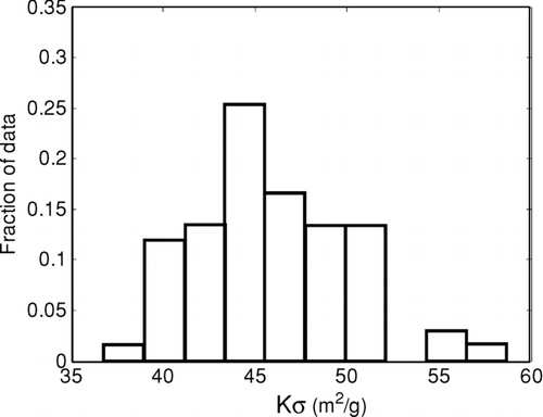
We conducted an analysis similar to the one described to determine the Kσ for pyrolytic carbon. For this analysis, we eliminated samples that had no charring, as well as samples that contained native LAC. We had only 11 samples with charrable material but no LAC, mostly from smoldering wood combustion that was prevented from flaming. Values of Kσ for 67 10 s averages are shown in ; they did not depend on filter transmittance (R2 = 0.03). These values average 46 ± 4.4 m2/g, higher than most of the values for LAC. This is consistent with other observations (CitationChow et al., 2004; CitationSubramanian et al., 2006). High values of Kσ could be caused by PC existing as coatings on fibers rather than as particles. PC may form either from adsorbed gases (CitationYang and Yu, 2002; CitationChow et al., 2004) or from fiber coatings that were originally liquid (CitationSubramanian et al., 2007).
Because Kσ is different for PC and LAC, it can be used to differentiate PC and LAC. (If they were identical, addition of ATN in the equation would result in an ill-conditioned matrix.) CitationChow et al. (2004) explored a similar apportionment, but did not use the approach to identify carbon evolving at different times.
5. EXPERIMENTAL DATA FOR THE LAST CONSTRAINT
Equations (1), (2), and (7) provide three simultaneous equations, an insufficient number to solve for four unknowns. A fourth equation could come from two types of constraints. Confirmation that either PC, LAC, or OCv is not released under specific conditions would provide a simple equation (for example, Δ LAC = 0). This approach is implicitly used in traditional TOA, but previous literature has called such assumptions into question. Knowledge about the fractional loss of a specific carbon group could also provide a constraint.
In this section, we seek these additional constraints so that the TOA system can be fully determined. In section 5.1, we examine the temperatures at which unmixed compounds are released during oxidation. Section 5.2 briefly discusses whether expected reactions in the atmosphere might alter those oxidation times. Finally, section 5.3 discusses our attempts to determine carbon yields. Most of these were unsuccessful and are provided here as cautionary notes.
5.1. Oxidation Temperature for PC, OC and LAC
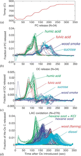
In , we compare oxidation temperatures of pyrolytic carbon, organic carbon, and native light-absorbing carbon. shows the temperature after oxidizer was introduced, while –d shows the average fraction of different types of samples released at each temperature. Supplemental Information (S1) contains a color version of this figure which shows results for each sample. It demonstrates that there is general consistency among the samples except as discussed below.
FIG. 6 Oxidation temperatures for LAC, PC, and OC remaining after He (inert) analysis. Each curve has been normalized by the total LAC, PC or OC evolving in the final stages.
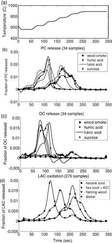
Samples representing pyrolytic carbon, shown in , are those which have no native LAC, determined by comparing the filter transmittance before and after the analysis. A constant value of Kσ was used to infer the quantity of PC; because the release at each time is normalized to total carbon, this value does not affect the figure. These samples include wood smoke, sucrose, humic acid and fulvic acid. Other samples either contained LAC or did not produce enough PC to examine. The figure shows a bimodal distribution: PC generated from humic acid oxidizes early (below 700°C), while PC from wood smoke and sucrose oxidizes at higher temperatures. We do not know whether PC from humic acid and from wood smoke is fundamentally different. Rather, the data indicate that PC oxidizes more quickly when it is in close contact with organic carbon. Multiple curves are shown for fulvic acid because the response differs from sample to sample. In lightly-loaded fulvic acid samples, carbon is more completely driven off in the inert atmosphere, while OC remains in heavily-loaded samples. The PC formed in the lightly-loaded samples is not in contact with organic carbon and oxidizes later, while the PC that remains in contact with organic carbon reacts as soon as the temperature increases under oxygen.
shows the OC inferred by subtracting a PC estimate (Δ ATN/ Kσ, where Kσ = 45 m2/g) from total carbon released for the same samples shown in . The noise in the figure comes from noise in the transmittance signal used to infer PC. OC remaining after the inert environment appears to oxidize below 700°C. This temperature is probably an upper bound on the temperature required for OC oxidization, because humic acid has a higher molecular weight than complex atmospheric organic matter (Graber and Rudich, 2006).
Finally, shows oxidation of LAC. Samples which showed pyrolysis in a helium atmosphere, and samples with organic carbon release at the end of the final helium step, are excluded to avoid misinterpretation of the LAC response. LAC and PC oxidize at similar temperatures, and LAC from different sources evolves at significantly different temperatures. CitationWatson et al. (1994) also pointed out that LAC from diesel and gasoline engines oxide at significantly different temperatures.
To summarize the expected reactions in an oxidizing atmosphere: (1) PC in our samples oxidizes below 700°C when organic carbon is present, and above 700°C when OC is not present. (2) OC is usually completely oxidized below 700°C. (3) Oxidation of pure LAC begins around 700°C. It is possible that OC could also initiate lower-emperature oxidation of LAC, but we did not examine samples containing both OC and LAC. However, as others have demonstrated and as we show in the next section, other elements in the sample can cause oxidation at lower temperatures.
PC can also be released from humic-cid samples in an inert-as environment. We observed this early release of PC only in humic acid samples, and we hypothesize that it occurs because carbon reacts with oxygen in the humic acid itself. However, most mixed atmospheric aerosol contains oxygen, so release in an inert environment could also be expected for ambient samples.
5.2. Shifts in LAC Oxidation
Several investigators (CitationFung, 1990; CitationNovakov and Corrigan, 1995; CitationMartins et al., 1998) have reported that potassium and mineral oxides catalyze the oxidation of LAC. We examined catalysis by KCl (a common component of biomass smoke; CitationLi et al., 2003) and three other processes that could occur during atmospheric mixing or processing to identify the effect on the release temperature of LAC. Our purpose was not to conduct an exhaustive study of all possible changes, but to place boundaries on changes in LAC oxidation temperature compared to unaltered LAC.
After LAC was deposited on filters in the laboratory tests, we exposed some of the laboratory samples to simulated atmospheric processing to determine whether chemical reactions affected thermal response. For each comparison, we analyzed two punches from a single collection filter. One punch was analyzed without treatment; the other was subjected to one of four treatments including (1) doping with KCl (43 filter pairs); (2) doping with (NH4)2SO4 (12 pairs); (3) exposure to ultraviolet light for 10 h (18 pairs), and (4) exposure to high concentrations (5%) of ozone (12 pairs).
Treatment with ultraviolet light and ozone had no effect. The presence of ammonium sulfate delayed oxidation by only a few seconds. We report these otherwise negative results as a small contribution to understanding the causes of LAC change (or lack of change) in thermal oxidation.
The only significant shift in oxidation temperature resulted from catalysis by KCl, as shown in . When KCl is added, LAC evolves from the filter as soon as oxygen is introduced. In no case was hexane soot released before the introduction of oxidizer, even at the highest KCl loadings. In similar experiments with wood soot, organic carbon was also present on the filter. Loss of absorbing aerosol in the KCl-doped samples occurred before the oxidizing atmosphere was introduced, while it did not occur in the control samples. Therefore, catalysis by KCl occurs only when oxygen is present either in the analysis atmosphere or in the sample. However, the presence of oxygen in the sample cannot be predicted; so LAC could be lost even at the lowest temperatures. The results shown here are extreme cases, because the mass ratio between K and EC was much higher than would be observed in atmospheric samples (0.4 to 3.6).
Nevertheless, we conclude that catalytic oxidation means that the analysis must account for evolution of LAC even below 700°C. Thus, below 700°C in an environment containing oxygen, PC, OC and LAC may evolve from the filter. Above that temperature, PC and LAC may evolve together.
5.3. Investigations of Carbon Yield
As we observed in our discussion of thermabsgrams, non-volatile, non-absorbing organic carbon can remain in the sample even after heating to high temperatures in an inert atmosphere. If the amount of this “heavy” OC were known, it could be used to constrain the groups evolving in the early part of the oxygen atmosphere.
We attempted to predict the amount of OC remaining on the filter to obtain additional constraints. These efforts are summarized in . First, we confirmed that the gentle slope of OC in each step would eventually return to zero, by using temperature programs with longer constant-temperature steps (not shown). We investigated whether a projection such as the one shown in , could be used to estimate the amount of OC remaining on the filter. We tried this projection for each of the latter two steps (615° and 870°C), reasoning that if a correction were possible for the second-highest temperature, it might also be possible for the IMPROVE-type analysis at 550°C.
FIG. 7 Attempted corrections for heavy organic carbon. (a) Demonstration of projection method; (b) results of projection method; (c) release rate versus carbon remaining on filter.
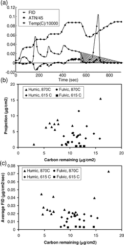
shows the results of this analysis for humic and fulvic acid samples. There is no relationship between the amount of OC projected and the amount actually remaining (R2 = 0.001 at 615°C; R2 = 0.077 at 870°C). Accounting for PC present did not improve the relationship. For four of 20 samples, the slope was so low that we were unable to construct a projection which reached the x-axis. A second attempt at estimating semi-volatile OC is shown in . We hypothesized that the release of this OC could be a first-order loss depending on the amount present on the filter. The figure shows release rate during the portion of the temperature step with constant slope, compared with the amount of carbon on the filter at that time. Again, there is no relationship (R2 = 0.008 at 615°C; R2 = 0.226 at 870°C).
These observations show that even high temperatures are insufficient to drive off heavy organic molecules. Many samples contain this heavy OC, as shown in published thermograms which exhibit a long tail with a gentle slope and a non-zero carbon release. An optical trace added to these thermograms, as demonstrated here, could identify whether this slowly-evolving carbon is wholly absorbing. Our results show that it is not. Heavy, non-absorbing OC can also be created during heating, as demonstrated by the presence of multiple release peaks during analyses of pure substances which do not char (not shown).
Furthermore, it is not possible to estimate the OC remaining on the filter, even when sample composition is well known. Release of some material (e.g., fulvic acid) is minimal at 615°C, which is greater than the highest temperature in the IMPROVE method. The presence of this heavy OC may therefore go undetected. It may also enable the co-evolution of PC, and possibly LAC, as soon as oxygen is introduced to the reaction chamber. Thus, allowing this OC to remain on the filter leads to the worst possible situation: three co-evolving groups, two equations, and no way to estimate a third constraint. The lower the maximum temperature in the inert mode, the less likely it is that this heavy OC will be released or observed.
We also attempted to quantify carbon yields for different carbon groups under other conditions. Many of these included exploiting kinetic rates in the hopes that they would identify the nature of the material being released. Often, release rates resembled first-order kinetics; for example, apparent activation energy for oxidation of LAC was similar to that reported for soot (CitationLee et al., 1962). However, the samples did not follow the postulated relationships at all temperatures, and the inter-sample variability in the inferred parameters was great enough that information could not be extracted from single samples. Other physical explanations, such as temperature-dependent phase transitions and mass diffusion limitations, did not explain the observed behavior, either.
6. TOA AS AN UNDERDETERMINED SYSTEM
Sections 5.1 and 5.2 show that temperature and analysis atmosphere are insufficient to constrain the groups evolving from the filter, and section 5.3 showed that loadings of particular groups could not be inferred from the rates of carbon release. The failure to identify such constraints is disappointing; it means that the system may remain underdetermined during parts of the analysis. In the first part of the analysis (helium atmosphere), the underdetermined system exists at high temperatures if PC has formed, if LAC is present, and if oxygen and a catalyst is available to promote the evolution of PC and LAC. Because the presence of oxygen is likely, and the availability of catalytic material is unknown, the system should be considered underdetermined if PC has formed. Later in the analysis (oxygen atmosphere), the system is underdetermined below 700°C if PC formed earlier in the analysis, if LAC is present, and if OC was incompletely removed in the helium atmosphere.
We now implement the simultaneous equations that describe the TOA response. The solution to a fully-determined system is a point in 3-space, where the axes of that space represent changes in OC, PC, and LAC. The solution to an underdetermined system which contains one more unknown than the number of equations is a line in 3-space. Any point on this line may be chosen as the result of the analysis, but in fact, other points along the line represent equally valid solutions, consistent with the analyzer's output. Physical considerations further limit the range of solutions. For example, during times when no transformations other than evolution are occurring, changes in all groups have the same sign. The valid solutions lie along a line segment in 3-space, and the span of the line segment represents the solution uncertainty.
Instead of declaring that material evolving at a particular step is OC, LAC or PC, when clearly such may not be the case, we identify a range of solutions: how much of the evolving carbon could be OC, LAC or PC based on physical consideration? This approach not only provides a quantitative estimate of uncertainty in existing TOA results, but it offers a new perspective on comparing temperature protocols. A protocol is optimal if it produces the lowest uncertainty.
6.1. Modeling the Underdetermined System with REACTO
shows the analysis pathway for our program, ReAnalyzing Carbon Traces Optically (REACTO). We first describe the solution procedure that produces a central estimate of LAC when a fourth constraint is always available; that is, the system is fully determined. First, carbon release and laser signals are read from the recorded data, and values of Δ ATN are calculated. A central value of Kσ transmission dependence is chosen from for LAC, and the asymptote a is guessed, since it varies for each sample. The central value of Kσ for PC is chosen from . Equations (1), (2), and (7), and the equation representing the fourth constraint, form a set of simultaneous equations that is written as a matrix equation. This equation is solved at every 10 s time step during the analysis. Any particular value of a results in a prediction of net PC and LAC. However, the net of PC formation and loss must be zero, and the value of a is iterated until this zero value is achieved. Note that the selection of K(τ)σ from imposes a requirement that the absorptive properties of LAC be continuous with transmittance.
FIG. 8 Analysis flow for TOA interpretation, implemented in MatLab™. Double boxes indicate where uncertainties in absorbance or carbon release are incorporated.
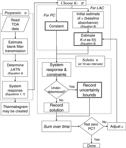
Next, we discuss how REACTO handles the underdetermined system. For each 10-second time step that is not fully determined, the solution is a line segment along which the relationship between OC, PC, and LAC is constrained. For the central case, we select the central value of LAC and the corresponding values of OC and PC. However, the ends of the line segment represent the extremes of the consistent solutions and these are also stored.
Finally, we explain how a “high” value of LAC would be calculated. The entire procedure described above would be repeated, except that the lowest value of Kσ would be selected for LAC and the highest would be selected for PC. Thus, lower values of PC mass and higher values of LAC mass are consistent with the available optics. If any portion of the analysis is underdetermined, REACTO keeps the highest value of LAC along the line segment solution, along with the corresponding values of PC and OC. Again, the other end of the solution segment is also stored.
6.2. Model Results
shows results of REACTO analysis, which provides the amount of each type of carbon released in each step. The upper panel () shows the analysis of the diesel exhaust sample in , which is a relatively simple case. There is little formation of PC, and no OC remains after the inert portion of the analysis. Thus, the attribution of the evolving carbon is unambiguous. The REACTO result indicates 76% EC, in agreement with the manufacturer's result of 74% EC.
FIG. 9 Uncertainty calculation for carbon release in each TOA step. (a) Diesel exhaust, a simple case, (b) Humic acid, a more complex case, (c) Wood smoke with both flaming and smoldering emissions. See text for further discussion. (Figure provided in color online.)
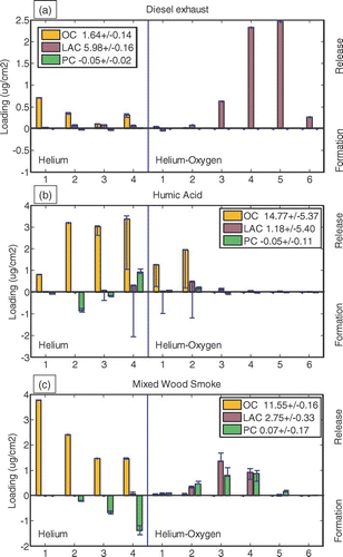
For the smoldering wood sample in , the REACTO results (not shown) identify the sample as 0.6% EC; the manufacturer's analysis is 1.2% EC. That sample contained no EC, so neither analysis is perfect, although the true value of zero is within the uncertainty of both REACTO and manufacturer's result.
is a humic acid sample, which is more complex. The sample contains a large amount of charrable OC, and a small amount of native light-absorbing material. REACTO correctly identified this sample as mostly OC. However, the uncertainties are high, particularly in the last step of the helium phase and the early steps of the helium-oxygen phase. Those uncertainties are caused by the underdetermined system (three co-evolving groups) in these steps. The Sunset analyzer also identified this sample as mostly OC, because it matches the filter transmittance at the beginning and end of the analysis. The formation of PC could have confounded the analysis if LAC had been present.
shows a realistic sample with charrable material: a source sample from a cooking fire with both flaming emissions (mostly EC) and smoldering emissions (mostly OC). REACTO estimates that LAC begins evolving first and that both PC and LAC evolve simultaneously. The EC estimate in this sample is 26% higher than the manufacturer's analysis. We note that the measured absorption of this sample was very high compared to the amount of EC in the manufacturer's analysis. The mass absorption cross-section would be 24 m2/g at 550 nm, whereas only 7.5 m2/g is expected for fresh (CitationBond and Bergstrom, 2006). Absorption by organic matter (e.g., CitationKirchstetter et al., 2004) or coated EC (CitationMartins et al., 1998; CitationSchnaiter et al., 2005) could lead to high absorption relative to EC. However, the underestimation of EC due to the presence of pyrolyzed PC (CitationChow et al., 2004) could be another cause of apparent high absorption. REACTO estimates for EC in most of our wood-smoke source samples were higher than the manufacturer's estimate by similar percentages.
shows REACTO estimates of EC for diesel exhaust (CitationSubramanian et al., 2008) and wood smoke with mixed flaming and smoldering combustion (CitationRoden et al., 2008), compared with the Sunset interpretation of the same sample analyses. Because there is little to no charring in diesel samples, uncertainties are low and REACTO EC is similar to Sunset EC. Because wood smoke chars and creates PC, the value of EC from these analyses is more uncertain. The greater disagreement in samples dominated by wood smoke was also reported by CitationSchauer et al., (2003) and CitationSubramanian et al., (2006). The larger values of REACTO EC compared with the instrument's analyses are in accordance with previous findings by CitationChow et al., (2004), who found that EC using transmittance monitoring was lower than EC using reflectance monitoring. Accounting for the greater Kσ of pyrolytic carbon demonstrates that the transmittance-based EC could indeed be biased high, in accordance with the theory presented by CitationYang and Yu (2002).
FIG. 10 Comparison of REACTO EC estimates and manufacturer's (Sunset) EC estimates for identical samples. (Figure provided in color online.)
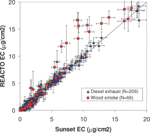
In , uncertainties in the x-direction are those reported by the Sunset instrument; uncertainties in the y-direction are those determined by REACTO, plus the 5% uncertainty in total carbon assumed by the Sunset instrument and 0.3 μ g/cm2 for the blank filter (Section 4.1 and Supplemental Information S3). Uncertainties for diesel exhaust aerosol are 1.3 to 2.2 times greater than those reported by the Sunset analyzer (10th and 90th percentiles), while those for wood smoke are 1.5 to 5 times greater. We also note that the REACTO uncertainty estimates sometimes do not overlap the Sunset EC estimate. This occurs because of the constraint that the absorption of each carbon group is a continuous function of temperature. The manufacturer's analysis assumes a sharp discontinuity in optical properties at the OC/EC split point, and we consider this assumption physically unreasonable.
What have we gained by adding complexity to the analysis in an already controversial method? REACTO accounts for many of the analysis imperfections which are suspected in TOA. The aerosol community is certainly aware of such flaws, but has lacked a framework to account for them. For example, absorbing carbon is assumed to have the absorptive properties of PC before the OC/EC split, and the absorptive properties of LAC after the OC/EC split. We concur with other investigators that the two substances have greatly differing absorption. Such a sharp discontinuity during the analysis is unphysical and, in the case of transmittance monitoring, leads to underestimation of EC.
7. SUMMARY AND RECOMMENDATIONS
7.1. Outlook
We embarked on this study with the hope that combining thermal and optical data would yield enough additional information to interpret TOA results conclusively, regardless of the temperature protocol used. Because the system is underdetermined, such decisive conclusions were prevented. However, the tools developed here do provide quantitative data about uncertainty in each sample, and can be used to re-interpret existing analyses.
The addition of the ATN trace, resulting in a “thermabsgram,” allows rapid, qualitative interpretation of sample results. It allows visual confirmation of several occurrences that are postulated in OC/EC literature, such as loss of light-absorbing carbon before oxygen is introduced, or retention of organic carbon even at high inert mode temperatures. The Δ ATN/Kσ trace also allows the analyst to assess the timing of charring.
We confirm the results of other studies: (1) Release temperatures of PC and LAC are similar, and temperature cannot be used to differentiate these materials. (2) Optical properties of PC and LAC are greatly different. (3) Organic carbon may be retained after the inert atmosphere; this problem is exacerbated by low peak temperatures in the inert portion of the analysis. In this study, we quantify the temperature ranges where carbon groups do evolve for use in our model.
7.1.1. Limitations
This paper concentrates on methods in which initial sample heating occurs in an inert environment, an element common to most of the analysis done in the United States. The methods described here, if applied judiciously, might be used for protocols that conduct initial heating in oxygen (CitationCachier et al., 1989), but it has not been tested.
Likewise, we have not attempted to obtain optical cross-sections for filters monitored with reflectance, although relationships analogous to Kσ also exist for reflectance detectors (CitationEdwards et al., 1983; Campbell et al., 1995). These calibrations would be relatively easy to obtain given similar samples and the appropriate equipment.
7.2. Recommendations
Despite the fundamental uncertainties remaining in TOA, we recommend some procedures and research which, we believe, will reduce these uncertainties. The suggestions for further research are listed in order of complexity.
7.2.1. Changes to existing procedures
Implement quality control procedures for the laser signal The laser signal used to define the OC/EC split point plays a critical role in the determination of OC and EC. Because it is so important, the measurement of attenuation should be repeatable to at least one part in 100 at all times during the analysis. Temperature dependences should be well defined and accounted for, for loaded filters as well as blank filters. High-fidelity optics are quite possible with current technology. Both new and existing analyzers should demonstrate compliance with this requirement. More stable optics would also provide confidence in the results of the analysis procedure described here.
7.2.2. Further Research
Confirm values of Kσ for pyrolytic carbon In this study, Kσ for pyrolytic carbon had a narrow range of values and did not depend on transmittance. However, the number of samples used in this determination was small, and some of them were generated by pipetting liquids rather than by collecting aerosol. The difficulty of obtaining samples devoid of LAC and of heavy organic carbon resulted in this small number of samples. Targeted measurements should be used to verify these values for a wider variety of samples.
Confirm and explain varying Kσ by source We observed significantly different absorption cross-sections for LAC from different sources. Although this finding does not aid in apportionment, it is significant for radiative-transfer applications.
Explore reflectance to provide constraints During this research, an analyzer with only transmittance monitoring was available to us. Analyzers with both reflectance and transmittance probes are becoming available. The claim is made that reflectance is less sensitive to PC than is transmittance (CitationChow et al., 2004). Thus, the values of Kσ for reflectance might be significantly different between groups, but not proportional to the values of Kσ for transmittance. If so, reflectance could be used to provide a third constraint on the system, and the solutions to the system equations would be fully determined.
Explore filter media or procedures to yield more consistent K(τ)σ The variable nature of the transmittance with respect to carbon mass is a large source of uncertainty, and adds a requirement for iteration in REACTO. Uncertainty will be reduced if variability can be reduced.
Optimize protocols based on least uncertainty Measurement protocols in some networks may not be amenable to change in order to preserve trends. However, other measurement endeavors may not be so constrained, and may seek accurate rather than consistent measurements. CitationConny et al. (2003) identified sample behavior during the high-temperature portion of the inert analysis as a source of uncertainty, and optimized reduction in charring. CitationSubramanian et al. (2006) were not optimistic about finding a single protocol optimal for all samples. Nevertheless, the analysis tools presented here broaden the definition of optimization through the quantitative identification of uncertainty. If the constant value of Kσ for pyrolytic carbon is confirmed, then we concur with the CitationConny et al. (2003) recommendation to maximize charring, because the effects of charring can be easily disentangled.
SUPPLEMENTAL INFORMATION
“Revisiting thermal-optical analyses of carbonaceous aerosol using a physical model,” P. Boparai, J. Lee and T. C. Bond
S1. Color figure: Release times and temperatures for Pyrolytic Carbon (PC), Organic Carbon (OC), and Light-Absorbing Carbon (LAC)
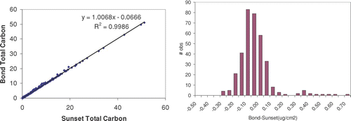
S2. Comparison of MatLab Code and Manufacturer's Results
Most of the REACTO interpretation is done with MatLab codes which read the manufacturer's raw data files directly. We discuss here a comparison between total carbon using our code and the manufacturer's provided program. Our interpretation differs slightly from the manufacturer results, as shown in . A key reason is the identification of the baseline carbon by the flame ionization detector, which drifts during the analysis. The response of this detector does not return to the initial value after the analysis, possibly because it requires time to recover from the very high calibration concentrations. Absolute difference between our analysis and the manufacturer's analysis is also shown in Figure SI. Diesel engine exhaust was chosen for this comparison because most of the sample carbon is released near the end of the analysis and would be more likely to confound the calibration. Thus, these samples represent the worst possible case.
S3. Correction for Laser Signal Dependence on Temperature
This discussion gives details on transmission of blank filters and the effect on uncertainty. Probability values (p) given in this section are obtained using an analysis of variance (ANOVA) in State™.
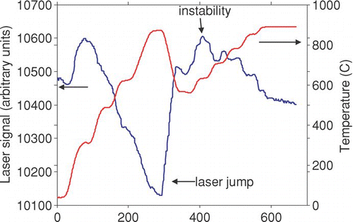
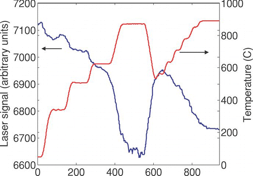
The laser signal sometimes exhibited one-time rapid changes (“jumps,” ) that appeared more often in the first filter analyzed each day (p < .0001 for 54 first versus 122 later filters). The jumps often appeared in conjunction with transitions across a specific temperature, and reversed as the sample cooled below those temperatures. We explored corrections for these jumps, for example by screening the first and second derivatives of the laser trace. However, with particle-laden filters, such a correction would be indistinguishable from rapid release of carbon. We also considered taking physical measures, such as ventilating the laser and detector, to minimize this occurrence. We did not pursue either of these possibilities because we are developing tools for retrospective analysis; a modified instrument would not exhibit the same level of uncertainty as existing measurements. Later discussions with the manufacturer indicated that this problem has been recently resolved.
The remaining analysis is based on the 122 samples that were not the first of the day. There are four temperature ramps during an analysis: heating during the He phase (“heating-1”), a brief cooldown before the He-Ox phase (“cooling-1”), heating during the He-Ox phase (“heating-2”), and cooling during the calibration period (“cooling-cal”). demonstrates the variation of laser signal with temperature for these phases. We performed linear fits for each ramp during each analysis, ignoring data at the very beginning and very end of the ramp. Large differences between phases were used to identify jumps (N = 17 or 14%).
For the remaining 105 samples, the laser signal typically varies by about 5%, decreasing monotonically with increasing temperature as shown in . If not accounted for, this variation could affect the OC/EC split time. Further, we will use transmittance during each second of the laser analysis to infer formation or loss of light-absorbing carbon, so we need a method of estimating ATN blank at each time and temperature.
We examined three methods of obtaining such an estimate, all relying on some measurement of transmittance during the calibration period:
| a. | A constant value of ATN, determined at a relatively low temperature (average of 275–325) represents ATN throughout the analysis. | ||||
| b. | The value of ATN determined in (I) represents a fixed point. The slope of the temperature dependence is determined separately for each period (heating 1, cooling 1, heating 2) by averaging the individual slopes from the 105 samples. | ||||
| c. | A quadratic fit to the ATN-temperature relationship during the calibration period represents the temperature dependence. | ||||
| d. | The value of ATN is constant, but it is adjusted by the temperature dependence observed during the calibration period. This is the method used in the manufacturer's software (D. Smith, personal communication, 2005). | ||||
For method II, we found that a linear relationship was a reasonable fit; 90% of the R-squared values were greater than 0.8, and 75% greater than 0.9. For method III, a quadratic fit was slightly better than a linear fit; polynomials of higher order did not provide better fits, and neither did accounting for differences between the filter and oven (thermocouple) temperature due to delayed heat transfer.
Having predicted ATN using the calibration period alone, we then calculate the average error (ϵ ATN during each period:
TABLE A1 Average error between measured and predicted laser signal, in arbitrary units, for tests without laser jumps. Laser signal for blank filter averages about 8000 units, so an error of 200 is a 2.5% error. Analysis based on fractional error (I/I0) did not have lower variance
Table A1 indicates that failing to correct for temperature dependence biases the transmittance low by about 300 units, or about 0.27 ng/cm2 of EC, where Ilow is the laser signal at a relatively low temperature. The other corrections have smaller biases. Method III, the quadratic fit, could not be made to do better on a generalized basis. Method II has the lowest bias, but it relies on a characterization—that is, measuring the slopes from our 105 samples—that may be instrument-specific. Repeating this analysis for each instrument in use would be undesirable. Method III can be performed using the data from only one sample when a fitting program is readily available. It has a small average bias (−0.03 to −0.06 μg/cm2) and uncertainties that are similar to the other methods, and it is incorporated into our analysis program. However, Method IV, used by the manufacturer, removes most of the bias and is simpler to use when no fitting program is available.
Predicting ATN blank as a function of time is applicable to some of the analysis in this paper. For the standard analysis, only the difference between ATN blank at the initial time and at the split point affects the OC/EC split. Estimates of bias and uncertainty in this difference also appear in Table Al. The uncertainties are added in quadrature and account for the covariance of the initial and later error predictions. We also account for the uncertainties introduced by laser jumps using Bayes' theorem. While the low average bias indicates that samples can be nearly corrected, on average, the high uncertainties are applicable to any single sample.
Because filter carbon loadings should be lower than about μg/cm2, and EC is often about 10–20% of the carbon for ambient samples (0.15–0.30 μg/cm2), this apparently small underestimate could be significant for lightly-loaded samples. For the laser signal in arbitrary units, the uncertainty of about 220 out of 8000 translates to an uncertainty of about 0.2 μg/cm2. This is the minimum value of uncertainty provided by the manufacturer's software. However, a more stable laser signal would reduce this inherent uncertainty.
Acknowledgments
We thank Sunset Laboratories, particularly David Smith, for rapid responses to queries about the operation of their instrument. We are grateful to two anonymous reviewers, David Covert, and the journal editor for extremely useful suggestions for presenting this complex study. We also thank Christoph Roden for providing mixed wood smoke samples. This work was funded by EPA STAR Grant RD-83108501. This paper has not been subjected to EPA's required peer and policy review and therefore does not necessarily reflect the views of the Agency. No official endorsement should be inferred.
Notes
*
x
o
↑
↕
!
REFERENCES
- Akhter , M. S. , Chughtai , A. R. and Smith , D. M. 1985a . The Structure of Hexane soot I: Spectroscopic Studies . Appl. Spectrosc. , 39 ( 1 ) : 143 – 153 .
- Akhter , M. S. , Chughtai , A. R. and Smith , D. M. 1985b . The Structure of Hexane Soot II: Extraction Studies . Appl. Spectrosc. , 39 ( 1 ) : 154 – 167 .
- Bond , T. C. , Anderson , T. L. and Campbell , D. 1999 . Calibration and Intercomparison of Filter-based Measurements of Visible Light Absorption by Aerosols . Aerosol Sci. Tech. , 30 : 582 – 600 .
- Bond , T. C. and Bergstrom , R. W. 2006 . Light Absorption by Carbonaceous Particles: An Investigative Review . Aerosol Science and Technology , 40 ( 1 ) : 27 – 67 .
- Cachier , H. , Brémond , M.-P. and Buat-Ménard , P. 1989 . Thermal Separation of Soot Carbon . Aerosol Sci. Tech. , 10 : 358 – 364 .
- Cadle , S. H. , Groblicki , P. J. and Mulawa , P. A. 1983 . Problems in the Sampling and Analysis of Carbon Particulate . Atmos. Env. , 17 ( 3 ) : 593 – 600 .
- Cadle , S. H. and Mulawa , P. A. 1990 . Atmospheric Carbonaceous Species Measurement Methods Comparison Study: General Motors Results . Aerosol Sci. Tech. , 12 : 128 – 141 .
- Cao , J. J. , Lee , S. C. , Ho , K. F. , Zhang , X. Y. , Zou , S. C. , Fung , K. , Chow , J. C. and Watson , J. G. 2003 . Characteristics of Carbonaceous Aerosol in Pearl River Delta Region, China During 2001 Winter Period . Atmospheric Environment , 37 : 1451 – 1460 .
- Chen , L.-W. A. , Chow , J. C. , Watson , J. G. , Moosmüller , H. and Arnott , W. P. 2004 . Modeling Reflectance and Transmittance of Quartz-fiber Filter Samples Containing 10 Elemental Carbon Particles: Implications for Thermal/Optical Analysis . J. Aerosol Sci , 35 : 765 – 780 .
- Chow , J. C. , Watson , J. G. , Crow , D. , Lowenthal , D. H. and Merrifield , T. 2001 . Comparison of IMPROVE and NIOSH Carbon Measurements . Aerosol Sci. Tech. , 34 ( 1 ) : 23 – 34 .
- Chow , J. C. , Watson , J. G. , Chen , L.-W. A. , Arnott , W. P. and Moosmüller , H. 2004 . Equivalence of Elemental Carbon by Thermal/Optical Reflectance and Transmittance with Different Temperature Protocols . Environ. Sci. Tech. , 38 : 4414 – 4422 .
- Cody , G. D. 1984 . “ The Optical Absorption Edge of a-Si:H ” . In Semiconductors and Semimetals , Edited by: Pankove , J. I. 11 – 82 . Orlando : Academic Press, Inc. .
- Conny , J. M. , Klinedienst , D. B. , Wight , S. A. and Paulsen , J. L. 2003 . Optimizing Thermal-Optical Methods for Measuring Atmospheric Elemental (black) Carbon: A Response Surface Study . Aerosol Science and Technology , 37 ( 9 ) : 703 – 723 .
- Countess , R. J. 1990 . Interlaboratory Analyses of Carbonaceous Aerosol Samples . Aerosol Sci. Tech. , 12 : 114 – 121 .
- Edwards , J. D. , Ogren , J. A. , Weiss , R. E. and Charlson , R J. 1983 . Particulate Air Pollutants: A Comparison of British “Smoke” With Optical Absorption Coefficient and Elemental Carbon Concentration . Atmos. Env. , 17 ( 11 ) : 2337 – 2341 .
- Fung , K. 1990 . Particulate Carbon Speciation by MnO2 Oxidation . Aerosol Science and Technology. , 12 : 122 – 127 .
- Gundel , L. A. , Dod , R. L. , Rosen , H. and Novakov , T. 1984 . The Relationship Between Optical Attenuation and Black Carbon Concentration for Ambient and Source Particles . The Science of the Total Environment. , 36 : 197 – 202 .
- Hakami , A. , Henze , D. K. , Seinfeld , J. H. , Chai , T. , Tang , Y. , Carmichael , G. R. and Sandu , A. 2005 . Adjoint Inverse Modeling of Black Carbon During the Asian Pacific Regional Aerosol Characterization Experiment . Journal of Geophysical Research. , 110 D14301, doi:10.1029/2004JD005671
- Heckman , F. A. 1964 . Microstructure of Carbon Black . Rubber Chem. Technol. , 37 : 1245 – 1298 .
- Huebert , B. J. and Charlson , R. J. 2000 . Uncertainties in Data on Organic Aerosols . Tellus , 52B : 1249 – 1255 .
- Huntzicker , J. J. , Johnson , R. L. , Shah , J. J. and Cary , R. A. 1982 . “ Analysis of Organic and Elemental Carbon in Ambient Aerosols by a Thermal-optical Method ” . In Particulate Carbon: Atmospheric Life Cycle , Edited by: Wolff , G. T. and Klimisch , R. L. 79 – 88 . New York : Plenum Press .
- Kirchstetter , T. W. , Corrigan , C. E. and Novakov , T. 2001 . Laboratory and Field Investigation of the Adsorption of Gaseous Organic Compounds onto Quartz Filters . Atmos. Env. , 35 ( 9 ) : 1663 – 1671 .
- Kirchstetter , T. W. , Novakov , T. and Hobbs , P. V. 2004 . Evidence that the Spectral Dependence of Light Absorption by Aerosols is Affected by Organic Carbon . Journal of Geophysical Research , 109 D21208, doi:10.1029/2004JD004999
- Lee , K. B. , Thring , M. W. and Beér , J. M. 1962 . On the Rate of Combustion of Soot in a Laminar Soot Flame . Comb. Flame , 6 : 137 – 145 .
- Li , J. , Pósfai , M. , Hobbs , P. V. and Buseck , P. R. 2003 . Individual Aerosol Particles from Biomass Burning in Southern Africa: 2. Compositions and Aging of Inorganic Particles . J. Geophys. Res. , 108 (D13):8484, doi:10.1029/2002JD002310
- Lim , H.-J. and Turpin , B. J. 2002 . Origins of Primary and Secondary Organic Aerosol in Atlanta: Results of Time-resolved Measurements During the Atlanta Supersite Experiment . Environmental Science and Technology , 36 : 4489 – 4496 .
- Martins , J. V. , Artaxo , P. , Liousse , C. , Reid , J. S. , Hobbs , P. V. and Kaufman , Y. 1998 . Effects of Black Carbon Content, Particle Size, and Mixing on Light Absorption by Aerosol from Biomass Burning in Brazil . Journal of Geophysical Research , 103 (D24):32041–32050
- Novakov , T. and Corrigan , C. E. 1995 . Thermal Characterization of Biomass Smoke Particles . Microchimica Acta. , 119 : 157 – 166 .
- Oanh , N. T. K. , Thiansathit , W. , Bond , T. C. , Subramanian , R. , Winijkul , E. and Paw-armart , I. 2007 . Compositional Characterization of PM Emitted from in-use Diesel Vehicles submitted
- Park , R. J. , Jacob , D. J. , Chin , M. and Martin , R. V. 2003 . Sources of Carbonaceous Aerosols Over the United States and Implications for Natural Visibility . J. Geophys. Res. , 108 (D12):4355, doi:10.1029/2002JD003190
- Polidori , A. , Turpin , B. J. , Lim , H.-J. , Cabada , J. C. , Subramanian , R. , Pandis , S. N. and Robinson , A. L. 2006 . Local and Regional Secondary Organic Aerosol: Insights from a Year of Semi-continuous Carbon Measurements at Pittsburgh . Aerosol Science and Technology , 40 ( 10 ) : 861 – 872 .
- Reid , J. S. , Hobbs , P. V. , Liousse , C. , Martins , J. V. , Weiss , R. E. and Eck , T. F. 1998 . Comparisons of Techniques for Measuring Shortwave Absorption and Black Carbon Content of Aerosols from Biomass Burning in Brazil . Journal of Geophysical Research , 103 (D24):32031–32040
- Roden , C. A. , Bond , T. C. , Conway , S. , Osorto Pinel , A. B. , MacCarty , N. and Still , D. 2008 . Laboratory and Field Investigations of Particulate and Carbon Monoxide Emissions from Traditional and Improved Cookstoves in press at Atmospheric Environment
- Schauer , J. J. , Mader , B. T. , DeMinter , J. T. , Heidemann , G. , Bae , M. S. , Seinfeld , J. H. , Flagan , R. C. , Cary , R. A. , Smith , D. , Huebert , B. J. , Bertram , T. , Howell , S. , Quinn , P. , Bates , T. , Turpin , B. , Lim , H. J. , Yu , J. and Yang , H. 2003 . ACE-Asia Intercomparison of a Thermal-optical Method for the Determination of Particle-phase Organic and Elemental Carbon . Env. Sci. Tech. , 37 ( 5 ) : 993 – 1001 .
- Schmid , H. , Laskus , L. , Abraham , H. J. , Baltensperger , U. , Lavanchy , V. , Bizjak , M. , Burba , P. , Cachier , H. , Crow , D. , Chow , J. , Gnauk , T. , Even , A. , Brink , H. M. T. , Giesen , K.-P. , Hitzenberger , R. , Huegelin , C. , Maenhaut , W. , Pio , C. , Carvalho , A. , Putaud , J.-P. , Toom-Sauntry , D. and Puxbaum , H. 2001 . Results of the “Carbon Conference” International Aerosol Carbon Round Robin Test Stage I . Atmos. Env. , 35 : 2111 – 2121 .
- Schnaiter , M. , Linke , C. , Möhler , O. , Naumann , K.-H. , Saathoff , H. , Wagner , R. , Schurath , U. and Wehner , B. 2005 . Absorption Amplification of Black Carbon Internally Mixed with Secondary Organic Aerosol . Journal of GeoPhysical Research , 110 D19204, doi:10.1029/2005JD006046
- Smith , D. M. and Chughtai , A. R. 1995 . The Surface Structure and Reactivity of Black Carbon . Coll. Surf. , 105 : 47 – 77 .
- Strader , R. , Lurmann , F. and Pandis , S. N. 1999 . Evaluation of Secondary Organic Aerosol Formation in Winter . Atmospheric Environment , 33 ( 29 ) : 4747 – 4965 .
- Subramanian , R. , Khlystov , A. Y. and Robinson , A. L. 2006 . Effect of Peak Inert-mode Temperature on Elemental Carbon Measured Using Thermal-optical Analysis . Aerosol Sci. Tech. , 40 : 763 – 780 .
- Subramanian , R. , Roden , C. A. , Boparai , P. and Bond , T. C. 2007 . Yellow Beads and Missing Particles: Trouble Ahead for Filter-based Absorption Measurements . Aerosol Science and Technology , 41 : 630 – 637 .
- Subramanian , R. , Bond , T. C. , Thiansathit , W. , Oanh , N. T. K. , Duleep , K. G. , Paw-armart , I. and Winijkul , E. 2008 . Source Characterization to Support Quantification of Co-benefits: A Piggyback Study in Bangkok Thailand submitted
- Venkataraman , C. , Reddy , C. K. , Josson , S. and Reddy , M. S. 2002 . Aerosol Size and Chemical Characteristics at Mumbai, India During the INDOEX-IFP (1999) . Atmospheric Environment , 36 : 1979 – 1991 .
- Watson , J. G. , Chow , J. C. , Lowenthal , D. H. , Pritchett , L. C. and Frazier , C. A. 1994 . Differences in the Carbon Composition of Source Profiles for Diesel-and Gasoline-powered Vehicles . Atmos. Env. , 28 ( 15 ) : 2493 – 2505 .
- Watson , J. G. , Chow , J. C. and Chen , L.-W. A. 2005 . Summary of Organic and Elemental Carbon/black Carbon Analysis Methods and Intercomparisons . Aerosol Air Quality Res. , 5 ( 1 ) : 65 – 102 .
- Weingartner , E. , Saathof , H. , Schnaiter , M. , Streit , N. , Bitnar , B. and Baltensperger , U. 2003 . Absorption of Light by Soot Particles: Determination of the Absorption Coefficient by Means of Aethalometers . J. Aerosol Sci. , 34 : 1445 – 1463 .
- Yang , H. and Yu , J. 2002 . Uncertainties in Charring Correction in the Analysis of Elemental and Organic Carbon in Atmospheric Particles by Thermal/optical Methods . Environmental Science and Technology , 36 : 5199 – 5204 .
