Abstract
The performance of an inlet for the size-resolved collection of aerosols onto a heating filament for subsequent thermal desorption is presented. The device resembles a cylindrical Differential Mobility Analyzer (DMA) in that a sample flow is introduced around the periphery of the annulus between two concentric cylinders, and charged particles migrate inward towards the inner cylinder in the presence of a radial electric field. Instead of being transmitted to an outlet flow, the monodisperse sample is collected on a nichrome filament that is flush with the inner cylinder. The primary benefit of this mode of sampling, as opposed to sampling into a vacuum using inertial separation, is that chemical ionization of the vapor molecules is feasible. In this study, we present a model of the device that is similar to that used to characterize the DMA. A prototype was constructed and tested at atmospheric pressure and at 18 Torr. The collection efficiency was determined indirectly by counting particles not collected by the device; and also by vaporization of the particles from the filament, chemical ionization of the vapor, and low-pressure ion mobility spectrometry of the ionized sample. The data demonstrate that the device is indeed size selective, but the collection efficiency curves are broader than predicted by the model.
INTRODUCTION
The need for size-resolved chemical analysis of aerosols has been well-documented in the literature over the last several decades. Countless studies have highlighted the sensitivity of adverse health and environmental effects of airborne particles to their size and chemical composition. This has led to the development of a variety of instruments for determining the size and chemical composition of fine and ultrafine aerosols in real time. Chemical composition is typically obtained by time-of-flight or quadrupole mass spectrometry, which requires high vacuum. Particle size measurements may be made aerodynamically (CitationJayne et al. 2000; CitationPhares et al. 2002) optically (CitationMurphy and Thomson 1995), or electrostatically (CitationVoisin et al. 2003). Optical sizing is not as precise, and is generally not feasible for ultrafine particles. Aerodynamic sizing for ultrafine particles requires that the particles be transmitted to vacuum, where particles may be desorbed using a laser or filament. Ionization of the vapor may be accomplished by electron beam or photoionization. Sizing by electrical mobility separation is typically done at atmospheric pressure. This allows for thermal desorption and chemical ionization prior to introduction of the ions into vacuum for mass analysis. CitationVoisin et al. (2003) developed the TD-CIMS instrument, which employs a differential mobility analyzer to select a particle size prior to sample collection. The monodisperse aerosol sample is then collected by electrostatic precipitation onto a heating filament for thermal desorption, atmospheric pressure chemical ionization, quadrupole mass spectrometry. A more recent study (CitationHeld et al. 2009) reports the same aerosol collection system coupled with ion trap mass spectrometry for easier identification of organic compounds.
Here, we characterize the performance of an aerosol inlet that collects particles having a narrow range of electrical mobility directly onto a filament for subsequent thermal desorption. Combining the electrostatic classification and collection in a single step allows for a more compact and lightweight instrument that may operate under a wide range of pressures, from under 1 Torr to atmospheric pressure. This is beneficial because low-pressure thermal desorption minimizes condensational loss of the vapor. Collection and desorption at low pressure may also be coupled with low-pressure chemical ionization, which minimizes ion clustering as compared to atmospheric pressure ionization. Thus the purpose of this study is to demonstrate controlled size-resolved collection onto a heating filament with reasonably high size resolution, and under a wide range of operating pressures.
INSTRUMENTATION
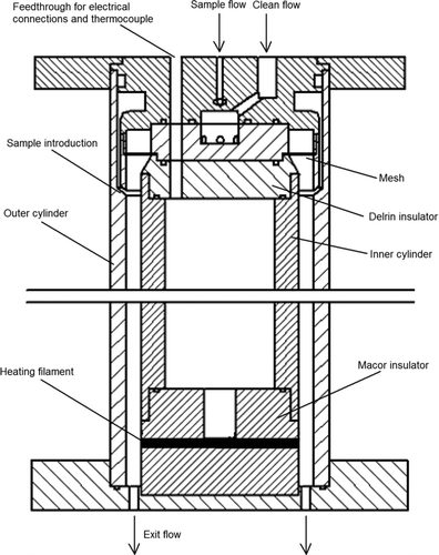
The electrostatic collection inlet, shown in , consists of two concentric polished stainless steel cylinders. The inner cylinder has an outside diameter of 6.35 cm, and the outer cylinder has an inside diameter of 7.62 cm. The sample aerosol flow is introduced uniformly around the periphery of the annular region between the two cylinders using the design reported by CitationChen et al. (1999) to eliminate the recirculation corner flows. The clean sheath flow enters the annulus upstream of the sample flow, and passes through a fine mesh to ensure uniformity. The outer cylinder is grounded. The inner cylinder is electrically isolated by a Delrin insulator on the upstream side, and by a cylindrical 6.35 cm diameter ceramic (Macor) insulator on the downstream side so that the surface of the ceramic is flush with the inner cylinder. Both junctions are face-sealed using Viton o-rings. The collection/heating filament is wrapped around the ceramic piece an axial distance of 29.8 cm from where the sample is introduced into the annulus. Feedthroughs for a thermocouple and electrical connections to the filament were sealed using a low-outgassing epoxy. The outer cylinder and the inner ceramic cylinder are sealed against a 6-inch conflat flange and the entire inlet assembly is clamped using 6 threaded rods spanning the length of the device. A series of 36 0.381 cm diameter holes were drilled into the lower conflat flange to allow the flow and sample vapor to exit the device. This corresponds to an open area fraction of 0.29. The flange may be mounted directly to a chemical ionization region, so that the vapor produced by desorption of the collected particles from the filament is rapidly analyzed, thus minimizing loss of the vapor to chamber walls or transit tubing.
The filament itself is actually a nichrome coil having a diameter of 3.6 mm. A 3.6 mm deep square groove was milled circumferentially around the ceramic cylinder so that, when the nichrome coil is inserted into the groove, the outer portion of the filament is flush with the ceramic surface, as shown in . This configuration is not ideal, because a deep groove (3.6 mm) stuffed with a coil may disturb the flow. However, this configuration was selected in order to minimize the contact area between the filament and the ceramic. When a flat strip or wire filament was wrapped around the ceramic cylinder, the heat transfer to the ceramic was so significant that the temperature of most of the filament remained low, while any portion that was not in direct contact with the ceramic (due to bowing or thermal expansion) became very hot causing in enormous temperature variation in the filament. In the current configuration, each loop of the coil makes three point contacts with the ceramic within the groove, and the coil is fixed in place by compression against the walls of the groove. The contact points are thus not affected by thermal expansion of the filament during heating. Indeed, the temperature of the filament is significantly lower in the vicinity of the point contacts; however, the temperature of the portion of the coil that is flush with the outer surface of the ceramic remains high and uniform (within 10% variation). Further, it is expected that particles are collected on this outer portion of the coil, rather than on the portion of the coil that is within the recess in the ceramic.
THEORY
Ideal Collection Efficiency
In order to calculate the expected collection efficiency onto the filament, we employ an approach similar to that presented by CitationKnutson and Whitby (1975) in their classic analysis of the cylindrical differential mobility analyzer transfer function. It was demonstrated in that study that, in the absence of Brownian motion, the trajectory of a particle having electrical mobility, Z p , could be completely characterized in terms of the fluid stream function, Ψ, and the electric flux function, Φ. In an axisymmetric geometry, these are defined in terms of the fluid velocity and electric field components in cylindrical coordinates:
FIG. 3 Drawing of the model domain showing the relevant geometrical parameters and the limiting fluid streamlines and electric field lines.
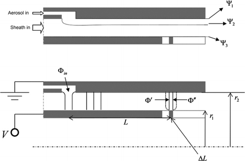
The initial value of the electric flux function, Φ in , is constant for all particles, since the magnitude of the electric field in the sample flow inlet is essentially zero. Unlike the DMA, the final stream function, Ψ∗ is equal to Ψ3, and the final electric flux function, Φ∗, has some finite distribution among particles that are collected onto the filament. Since the particle stream function is constant along any particle trajectory, Φ∗ may be written in terms of the bounding flow stream functions:
Assuming that particles enter along an initial fluid stream function, Ψ in , that is uniform and random in the range {Ψ1,Ψ2}, then Φ∗ is also a uniform and random in the range:
Note that keeping Z p and Φ in out of the intervals in Equations (Equation6) and (Equation7) ensures that these expressions are standard for both polarities of operation (i.e., V > 0 and V < 0, where V is the voltage applied to the inner cylinder and filament). A particle is collected onto the filament if
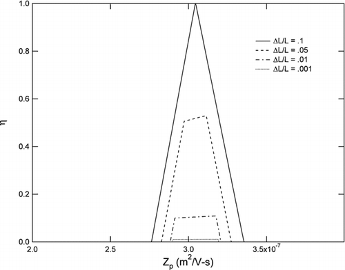
The collection efficiency, η, onto the filament is equal to the fraction of the interval in Equation (Equation7) that is intercepted by the interval {Φ ′,Φ”}. The resulting curve is shown in for a range of filament sizes and a clean to sample flow ratio of 10:1. The collection efficiency is plotted as a function of Z p /Z p ∗, where Z p ∗ ≡ − (Δ Ψ∗/Δ Φ∗) is the centroid mobility, and Δ Ψ∗ = (Ψ1 + Ψ2/2) − Ψ3. Note that, unlike a conventional DMA, the ideal efficiency curve deviates from a truncated isosceles triangle due to the dependence on mobility of the width, Q s /2π Z p , of the range in Equation (Equation7).
Diffusion Effects
As the particle size and the inlet pressure decrease, Brownian motion of the particles in the drift gas becomes increasingly important. The effect is to induce velocities normal to the expected particle streamlines and thus cause particles to stray from their trajectories. Following CitationStolzenburg (1988), this may be modeled as a diffusive process, whereby a collection of particles having the same electrical mobility attain particle stream functions that are normally distributed, such that
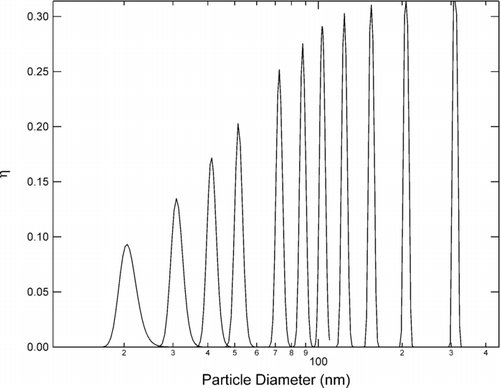
displays Equation (Equation12) for a range of inner cylinder voltages at an inlet pressure of 10 Torr, Q c /Q s = 10, Δ L = 1 cm, L = 30 cm, and a total volumetric flow rate of 84 L/min (corresponding to a sample flow rate of 0.1 L/min from atmosphere). The device is limited in particle size by diffusion and voltage ripple on the small end, and by electrical breakdown of the gas on the large end. Under the conditions presented in , the largest particle size sampled corresponds to 790 Volts—just below the breakdown limit of the gas.
EXPERIMENTS
Since particles are collected onto a filament, rather than transmitted through the device, target particles may not be directly counted for determination of the collection efficiency. Consequently, two indirect methods were employed for determining the filament collection efficiency. First, collection efficiency curves were inferred at atmospheric pressure from the number of particles that exited the inlet with and without a voltage applied to the filament. And second, collection efficiency curves were inferred at 18 Torr from analysis of the vapor that was desorbed from the filament upon heating. All of the presented experiments were performed using the prototype inlet described previously. The relevant dimensions are: L = 29.8 cm, Δ L = 0.36 cm, r 1 = 3.175 cm, and r 2 = 3.81 cm.
Particle Counting Method
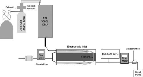
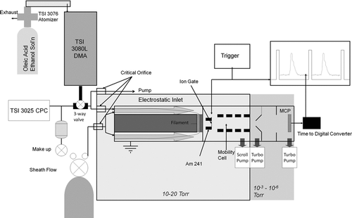
displays a schematic of the experimental setup for the measurements made at atmospheric pressure. Oleic acid particles were produced by solution atomization using a TSI 3076 atomizer and given an equilibrium charge distribution using a Kr-85 beta source. Particles having a narrow size distribution were selected using a TSI 3080L DMA system, and introduced directly into the inlet by suction downstream of the inlet. All particles exiting the DMA and entering the inlet were charged. The sheath flow rate in the DMA was 3.0 L/min, and the sample flow was 0.3 L/min. A total flow of 3.3 L/min was drawn through the inlet using a TSI 3025 condensation particle counter (CPC) sampling 0.3 L/min of the exit flow and a pump sucking 3.0 L/min through a critical orifice. The clean sheath flow into the inlet and the exit flow just upstream of the critical orifice were monitored using calibrated mass flow meters (Omega). Since the inlet was not mounted onto a chamber, the conflat flange was reduced to a ½ inch Swagelok connector for the exit flow.
For each particle size selected by the DMA, a total of four time-averaged particle count measurements were made using the CPC. First, with the inner cylinder and filament grounded, a baseline measurement, N 1, was made. This value was typically around 104–105 per cm3. Second, the same voltage was applied to the inner cylinder and the filament so that particles were collected by the inner cylinder and the filament. The CPC measured the number concentration, N 2, of particles that still exited the device. Third, the filament was grounded so that particles were only collected by the inner cylinder. Near the peak of the collection efficiency function, the measured concentration, N 3, increased by 103–104 from the previous measurement, N 2, indicating that particles were indeed collected by the filament. And fourth, both the inner cylinder and filament were grounded so that a second baseline measurement, N 4, could be made. The measured collection efficiency was determined from these measurements by normalizing the difference of N 3 and N 2 with the average of the two baseline measurements:
Vapor Analysis Method
Since the CPC is limited to ambient pressures, low-pressure characterization of the inlet was accomplished by analyzing the mass collected on the filament by low-pressure ion mobility spectrometry of the vapor produced upon desorption of the oleic acid from the filament. This experimental setup, shown schematically in , more closely resembles the conditions under which the inlet is meant operate for chemical analysis of aerosols. The vapor passes through the holes drilled into the conflat flange and directly into chemical ionization region, which consists of a 0.5 mCi Am-241 alpha source mounted inside a series of electrodes having an inside diameter of 1.0 cm. The alpha source initiates a series of gas-phase reactions, which produce protonated water cluster ions. These ions in turn ionize the oleic acid vapor molecules by proton transfer with near unity efficiency upon collision. The resulting ion cloud is gated into the ion mobility drift cell by a Bradbury-Nielson ion gate, allowing the protonated oleic acid ions to separate from the remaining ions present in the flow.
In this study, the low-pressure ion mobility cell is used solely to separate the oleic acid ions from the ions produced by the carrier air flow, so that the mass of the oleic acid collected on the filament may be measured. The 22.6 cm long mobility cell consists of a series of cylindrical electrodes separated by ceramic insulating rings. The field produced in the ion drift region is 40 V/cm and the pressure within the drift region is 13 Torr. The ion gate was pulsed at a frequency of 100 Hz, and the pulse duration was 0.3 ms. The pulse was produced by a function generator (Agilent model 33220A), which triggered a fast switch (EDR Inc, model 82855) for rapid opening and closing of the ion gate.
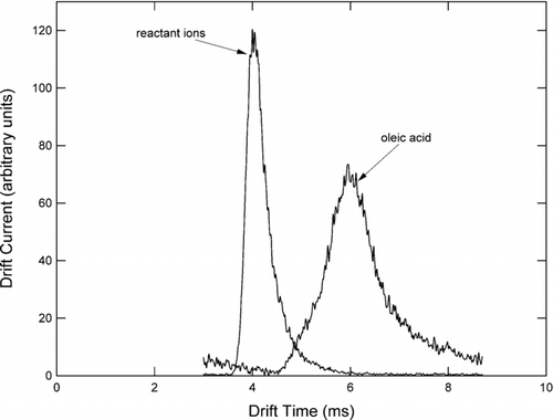
The function generator simultaneously triggered a time-to-digital converter (Ortec model 9353), which monitored the current pulses produced when individual ions impacted a microchannel plate detector (Burle) mounted in a Chevron configuration. Since the detector requires high vacuum for operation (< 10− 5 Torr), ions were focused into a beam using a series of electrostatic lenses while the neutral gas was skimmed away in a one-stage evacuation region. displays two ion mobility spectra obtained using the configuration described here. Air flowing through the reaction region produces a variety of positive ions primarily composed of protonated water and clusters of water. These relatively mobile ions produce a single peak between roughly 3.8 and 4.4 ms, labeled “reactant ion peak” in . Note that the width of the reactant ion peak is slightly larger than the ion gate pulse duration. This may be attributed to slight diffusive streamwise broadening of the ion cloud and the range of mobilities of the various water cluster ions that comprise the peak. When oleic acid was introduced into the system at high concentration, the entire reactant ion peak disappeared, and a new, broader peak corresponding to protonated oleic acid and its clusters appeared between 4.5 and 7.5 ms and is labeled in .
For a given voltage applied to the inner cylinder and filament, a range of sizes of oleic acid were selected using the DMA. For each size, a measurement was made as follows. The particle concentration exiting the DMA was measured using the CPC maintaining a sample flow of 0.3 L/min. Then a three-way valve was opened allowing the monodisperse aerosol flow to enter the sample inlet of the device through a critical orifice at a volumetric flow rate of 0.15 L/min (atmospheric pressure). The DMA sample flow was maintained at 0.3 L/min by drawing an excess flow of 0.15 L/min to a pump through a critical orifice. The clean sheath flow was filtered air drawn into the inlet through a critical orifice at a flow rate of 1.50 L/min (atmospheric pressure). With the inlet voltage turned on, the aerosol stream was collected for five minutes. This corresponds to an accumulated mass on the order of nanograms on the filament. Then the sample flow was turned off using the three-way valve, and the system was flushed for 10 min. This flush was necessary because the residual ethanol, which enters the inlet as vapor along with the aerosol, masks a portion of the oleic acid peak in the ion mobility spectrum. After the flush, an ion mobility spectrum was acquired over one minute, representing the baseline. Then the filament was heated above 330°C for 30 s, while an ion mobility spectrum was acquired for one minute. The heating temperature and duration were sufficient to desorb the entire sample from the filament. This was verified for each measurement by reacquiring a baseline spectrum and a second heating spectrum, and ensuring that these two spectra were identical.
A measure of the mass collected on the filament was estimated from the total ion count between 4.5 ms and 7.5 ms of the ion mobility spectrum. A baseline, obtained from the baseline spectrum between 4.5 ms and 7.5 ms, was subtracted from this value. Comparison with the model requires renormalization of the collection efficiency curves. This renormalization represents a mass calibration of the ion mobility spectrometer, in that the total ion count in the oleic acid mobility peak is proportional to the total mass collected on the filament. This is a function of the operating pressure, the chemical ionization efficiency, the transmission efficiency of the ion gate, the gate pulse frequency and duration, the transmission efficiency through mobility cell, and the ion transmission efficiency into vacuum. A detailed optimization of these was not done for these experiments and is beyond the scope of the current study. Nevertheless, the current configuration was sufficient to resolve the nanograms of mass collected on the filament during the sampling time. In the present study, the mass calibration is applied for qualitative comparison with the model, as described in the next section.
Effect of Aerosol Size Distribution on Collection Efficiency
Since the test aerosol produced by the DMA in these experiments has a finite size distribution, the measured collection efficiency, η m , may not necessarily be directly compared to the predicted collection efficiency function. Rather, a single measured collection efficiency represents an integral over the entire input aerosol size distribution, n(D p ):
The low-pressure experiments yield mass collection efficiency data, as opposed to number collection efficiency. A normalized mass collection efficiency, η M,m, may be obtained from the finite DMA transfer function and the inlet collection efficiency function:
RESULTS
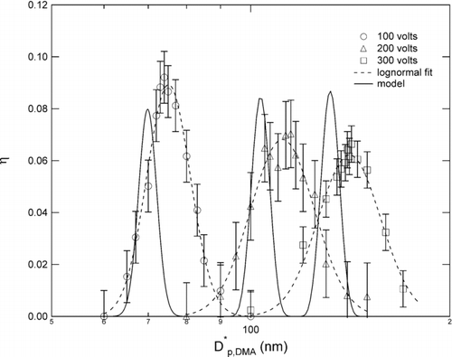
displays the measurements made at atmospheric pressure for applied voltages of 100, 200, and 300 Volts, and the corresponding predictions from the model, coupled with Equation (Equation17). The error bars used in the plot were determined from repeatability of the measurements, and were obtained separately for each voltage. The measured collection efficiency curves are broader than predicted and consistently shifted to a larger mean size. The area under the efficiency curve fit is significantly larger than the area under the predicted efficiency curve, suggesting that a larger mass would be collected from a polydisperse sample than predicted.
FIG. 9 Atmospheric pressure data for a cylinder voltage of 100, 200, and 300 Volts compared with model.
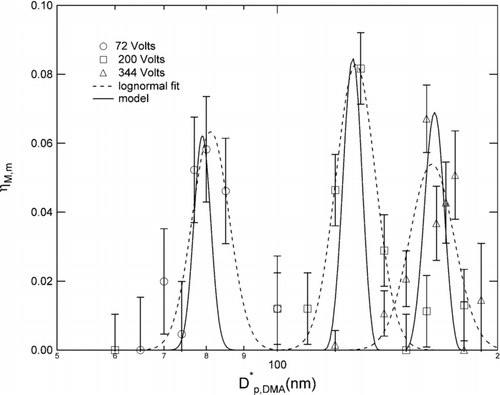
The low pressure data, presented in for applied voltages of 71, 200, and 344 Volts, respectively, exhibit collection efficiency curves that are also broader than predicted. The error bars were determined from repeatability of the measurements made near the peak of the measured collection efficiency curve for each voltage.
DISCUSSION
In general, the model predicts the optimally collected particle size reasonably well, especially for the low-pressure experiments. The measured collection efficiency functions, however, are consistently broader than predicted. In the discussion that follows, we present a few explanations to account for this observation, including fluid flow effects and electric field effects.
Fluid Effects
Some broadening of the size distribution as compared to the diffusion model may be expected, because of the possible presence of flow eddies induced at the sample flow introduction point or in the vicinity of the collection filament. These flow induced broadening effects should scale with Reynolds number. The Reynolds numbers were 66 and 33 for the atmospheric pressure and low pressure experiments, respectively. This may explain why the atmospheric pressure data exhibit slightly wider efficiency curves. However, the sample introduction was designed such that there are no recirculation or stagnation flow regions, and the flow enters the annulus tangentially to minimize flow mixing with the sheath. This design has been previously shown (CitationChen et al. 1999) to provide high-resolution mobility separation for the cylindrical DMA. It seems unlikely that the broadening would be caused by the sample inlet.
Another potential location for excessive flow mixing is at the filament. The presence of the groove within the ceramic would alter the flow by bending the fluid streamlines into the groove. This flow penetration becomes significant for flow Reynolds numbers less than 50, whereas the streamlines in the main flow are unaffected by the groove for Reynolds numbers greater than 50 (CitationStevenson 1973; CitationCieslicki and Lasowska 1999). The bending streamlines could cause a broadening of the collection efficiency curve and a shifting of the peak to larger sizes if the wall streamline does not remain uniformly attached to the filament. The effect should be more evident in the low-pressure experiment, in which the Reynolds number is less than 50. However, the presence of the coil filament within the groove likely causes further local flow disturbances that may result in further broadening of the collection efficiency curves beyond what may be expected solely from penetration of the flow within the groove.
Electric Field Effects
Another potentially significant effect concerns the electric field in the vicinity of the collection filament. In the model, the field was assumed to be purely radial and independent of axial location. However, since the filament must be electrically isolated from the conductive portion of the inner cylinder, there exists an axial component in the electric field at the leading and trailing edges of the filament. This causes an electrostatic focusing into the filament that would further broaden the collection efficiency curve. This effect may provide some explanation for why the measured peak widths are consistently larger than those predicted by the model. The model limitation stems primarily from Equation (Equation14), in which the particle stream function distribution is integrated from Φ” to Φ ′, corresponding to the electric flux functions at the trailing and leading edges of the filament. Using the commercial software SimION to determine the electric field in the vicinity of a coil having the geometry of the filament used in this study, we have computed that Δ Φ is roughly double the value predicted by Equation (Equation9). Incorporating this focusing effect into the model is analogous to doubling the length, Δ L, of the filament. However, doubling Δ L should cause roughly a doubling in peak collection efficiency, which is not observed in , and only a slight broadening of the collection efficiency curve. Note that a more rigorous three-dimensional particle tracking model may be required for describing particle deposition in the immediate vicinity of the coil filament.
There may also be some artifact of how the efficiency measurement is made at atmospheric pressure, since that experiment cannot account for particles that were removed from the flow downstream of the filament. There is no electrical ground within the ceramic cylinder, and there may be a residual electric field below the filament that continues to drive aerosols towards the ceramic beyond the location of the filament. However, a similar SimION analysis reveals that collection of aerosols onto the ceramic downstream of the filament could not lead to such a significant shifting and broadening of the collection efficiency curves without an accompanying increase in the peak height that approaches 100%.
Limitations of the Present Study
The experiments presented here did not include a direct measurement of the aerosol mass collected directly on the filament. The low-pressure experiments provided a qualitative determination of the size-selectivity of the inlet, but the lack of a definitive mass calibration of the ion mobility cell prevented a quantitative determination of the collection efficiency peak area, and thus a total collected mass. The discrepancy in the width of the collection efficiency peak between both sets of experiments and model precludes the application of the model to predicting the mass of aerosols collected onto the filament from a polydisperse aerosol for the prototype inlet analyzed here. Nevertheless, both the model and experiments demonstrate that the inlet is size-selective and may be operated at low pressure, facilitating transport of the sample vapor into the chemical ionization cell.
CONCLUSIONS
An aerosol inlet that collects a monodisperse sample directly onto a heating filament was described. A model allowing for diffusion effects was presented to predict the collection efficiency curves onto the filament. Measurements were made at atmospheric pressure using a condensation particle counter, and at low pressure using an ion mobility spectrometer. Both the model and the experiments demonstrate that the aerosol inlet is indeed size selective. There was some deviation in the size resolution and the optimally collected size between the model and experiments for the atmospheric pressure experiments. This may possibly be attributed to flow or electric field non-idealities. The collection efficiency maxima obtained at 18 Torr were in better agreement with those predicted by the model, though the shape of the collection efficiency curve may be affected by electric field or flow distortions near the filament.
This work was supported by the California Air Resources Board and the U.S. EPA.
REFERENCES
- Chen , D. R. , Pui , D. Y. H. , Mulholland , G. W. and Fernandez , M. 1999 . Design and Testing of an Aerosol Sheath Inlet for High Resolution Measurements with a DMA . Aerosol Sci. Technol. , 30 : 983 – 999 .
- Cieslicki , K. and Lasowska , A. 1999 . Experimental Investigations of Steady Flow in a Tube with Circumferential Wall Cavity . J. Fluids. Eng. , 121 : 405 – 409 .
- Held , A. , Rathbone , G. J. and Smith , J. N. 2009 . A Thermal Desorption Chemical Ionization Ion Trap Mass Spectrometer for the Chemical Characterization of Ultrafine Aerosol Particles . Aerosol Sci. Technol. , 43 : 264 – 272 .
- Knutson , E. O. and Whitby , K. T. 1975 . Aerosol Classification by Electrical Mobility: Apparatus, Theory, and Applications . J. Aerosol Sci. , 6 : 443 – 451 .
- Jayne , J. T. , Leard , D. C. , Zhang , X. F. , Davidovits , P. , Smith , K. A. , Kolb , C. E. and Worsnop , D. R. 2000 . Development of an Aerosol Mass Spectrometer for Size and Composition Analysis of Submicron Particles . Aerosol Sci. Technol. , 33 : 49 – 70 .
- Murphy , D. M. and Thomson , D. S. 1995 . Laser Ionization Mass-Spectroscopy of Single Aerosol-Particles . Aerosol Sci. Technol. , 22 : 237 – 249 .
- Phares , D. J. , Rhoads , K. P. and Wexler , A. S. 2002 . Performance of a Single-Ultrafine-Particle . Aerosol Sci. Tech. , 36 : 583 – 592 .
- Stevenson , J. F. 1973 . Flow in a Tube with Circumferential Wall Cavity . J. Appl. Mech. , 40 : 355 – 360 .
- Stolzenburg , M. R. 1988 . An Ultrafine Aerosol Size Distribution Measuring System , Ph.D. Thesis Minneapolis : University of Minnesota .
- Voisin , D. , Smith , J. N. , Sakurai , H. , McMurry , P. H. and Eisele , F. L. 2003 . Thermal Desorption Chemical Ionization Mass Spectrometer for Ultrafine Particle Chemical Composition . Aerosol Sci. Technol. , 37 : 471 – 475 .
