Abstract
Although the importance and implications of studying expiratory droplet concentration distribution in indoor environments are obvious, experimental measurements are very scarce and incomplete. In the work described herein, spatial and temporal aerosol concentrations generated by a modeled expiratory process were studied experimentally. Two heated manikins were placed inside a chamber with either a displacement ventilation system or a ceiling supply and ceiling return ventilation system. One of the manikins emitted 0.05 micrometer monodisperse polystyrene microspheres mimicking the generation of expiratory droplets. Flow characteristics were measured by a hot-film anemometry system before and after the momentary emission of aerosols at three locations. The temporal concentration profiles at eight locations were also measured. The results show that a high-speed air jet easily penetrates the boundary layer of the manikin regardless of the ventilation system used. Transient ventilation effectiveness was also evaluated and compared for both ventilation systems. The results show that the ventilation effectiveness of displacement ventilation is always higher than that of ceiling-type ventilation. Experimental observation also suggests that the presumption of complete mixing must be applied cautiously.
1. INTRODUCTION
Wells was the first to hypothesize the droplet nuclei transmission of airborne infections in the 1950s (Wells 1954). Although this concept has been demonstrated experimentally, it has not received much attention from researchers. Since the outbreak of severe acute respiratory syndrome (SARS), there has been research interest from scholars in a diverse range of fields in the control and reduction of the human-to-human airborne transmission of pathogens indoors. Within the space of a few years, the transport of droplets exhaled indoors has become an important topic in aerosol sciences, building sciences, and public health. The recent outbreak of a new strain of Human Swine Influenza (H1N1) in May 2009 further aroused public awareness of the airborne transmission pathway of highly contagious pathogens. An infected person (the source) will emit a large quantity of droplets that contain viruses or bacteria within a very brief period (CitationChao and Wan 2006).
Exposure is a function of breathing concentration and exposure time. The temporal evolution of aerosol concentration in an indoor environment is an important factor determining the ultimate exposure level of an individual. This is particularly true for episodic events like sneezing or coughing. In enclosed environments such as air-conditioned offices, the dispersion and transport of expiratory droplets depend on the ventilation scheme, the droplet bulk density and volatility, and the speed and duration of the expiratory process. In addition to the above factors, the exposure level of susceptible individuals also depends on inhalation duration and the separation and orientation of the source and susceptible individuals.
The mean airflow pattern significantly affects the overall distribution of droplets. A ceiling supply and ceiling return scheme (hereafter referred to as mixing ventilation, or MV) is the most popular ventilation arrangement for commercial buildings. In schemes of this type, high-velocity cooled air is discharged through supply grills and warm air is expelled through return grills. The spatial concentration profile of the MV scheme is often assumed to be homogeneous or near-homogeneous. However, the validity of the presumption of complete mixing relies solely on the airflow characteristics of the space concerned, which in turn depends on the number and location of supply and return grilles. A high flow rate does not necessarily imply good mixing, particularly for aerosol pollutants (CitationChen et al. 2006).
Displacement ventilation (DIS) schemes exhibit completely different characteristics to those of MV schemes. DIS schemes supply cooled fresh air at a low velocity to occupied zones and exhaust hot air via exhausts located in the ceiling. The airflow pattern of DIS schemes can lead to a large portion of indoor contaminants escaping via the exhausts without any great degree of internal mixing (CitationZhao et al. 2004). DIS schemes are therefore often seen as more effective in removing contaminants and reducing the risk of cross-contamination between occupants. Moreover, from the energy consumption point of view, DIS schemes can reduce chiller energy use due to the formation of air temperature stratification and a higher supply air temperature (CitationOlsen and Chen 2003; CitationLau and Chen 2006).
The literature includes a few recent studies that model the transport of expiratory droplets indoors (Zhang and Chen 2008; CitationLai and Cheng 2007; CitationQian et al. 2008; Mui et al. 2009). Other researchers have numerically studied the transport of bacteria through an expiratory process in an isolation room (CitationZhao et al. 2009; CitationRichmond-Bryant 2009; CitationHuang and Tsao 2005). The detailed features of body geometry have also been examined in a study of personal exposure when two occupants are positioned opposite each other (CitationGao and Niu 2006). In comparison with the outcomes of numerical modeling, the experimental results obtained in this latter study were limited and far from complete. Chao and his colleagues have measured the dispersion of expiratory droplets in various indoor environments. Polydisperse aerosols were found to have a similar distribution after dispersing via a natural expiratory process generated in both an empty chamber and a mock-up aircraft cabin (CitationChao and Wan 2006; CitationWan et al. 2009). The droplet size profiles were measured using an interferometric Mie imaging technique.
Qian et al. (2006) studied droplet dispersion in a mock-up hospital ward. Tracer gas was used to quantify the concentration distribution and both local ventilation effectiveness and a personal exposure index were calculated. The results showed that displacement ventilation systems are not suitable for hospital wards. CitationZhang and Chen (2006) measured the temperature, velocity, and concentration of submicron particles of 0.7 μm with four heated human simulators in a full-scale environmental chamber with an underfloor ventilation system. The authors concluded that this system offers the best particle removal efficiency for their steady-state measurements. CitationFriberg et al. (1996) compared the performance of displacement ventilation with that of a conventional positive pressure system during rigidly standardized sham operations. They concluded that although the displacement ventilation system examined was more efficient in eliminating particles of less than 10 μm, the major shortcoming of the system was its failure to eliminate a sufficient quantity of larger bacteria-carrying airborne particles.
All previous experimental studies have used polydisperse droplets to mimic the natural expiratory droplet size distribution. Nevertheless, almost all the physical characteristics of aerosols depend on size (i.e., settling velocity), the diffusion coefficient, inertia, etc. The authors of this study have recently measured the spatial concentration of expiratory droplets at three locations in a scaled ventilated chamber with displacement ventilation. Two heated manikins, one of whom emitted monodisperse droplets, were placed in the chamber (CitationBerrouk et al. 2009). No experimental result has been reported on the distribution of expiratory-generated aerosols under different ventilation schemes. The study reported in this paper focused on the influence of conventional and displacement ventilation systems on the transport of aerosols via an expiratory process. To facilitate this work, an experimental setup based on that employed by CitationBerrouk et al. (2009) was designed and fabricated, subject to substantial modifications. The goal was to measure the distribution of expiratory aerosols and ventilation performance in a mechanically ventilated space. Monodisperse aerosol particles of a single size of 0.05 μm were generated through an atomization process and emission velocity was set to approximately 8 ms–1 to mimic the natural expiratory process through which large viruses are emitted. The objectives of the study were to investigate the detailed airflow and spatial characteristics and the temporal concentration of monodisperse aerosols after being momentarily emitted under MV and DIS systems in a scaled chamber with heated sources.
2. Experimental Set-Up and Measurement
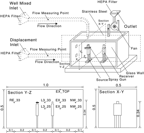
In light of the prior research finding that the concentration boundary layer is much thinner than the momentum boundary layer (Lai and Nazaroff 2000), it is critical to ensure that the internal surfaces of chambers used in experimental studies are very smooth. Besides, the materials selected for this experiment had low electrostatic residual charges. A high-quality tempered glass/stainless steel chamber was built () with dimensions of 0.5 × 0.5 × 1 m3 (H × D × W) as a 1:5 scaled chamber. The chamber was designed in a very flexible way to allow for both MV and DIS to be studied. The airflow was induced by means of a fan and was regulated by a power supply. The inlet and outlet ducts were made of 50-mm square stainless steel. The length of the inlet duct was at least 50 times the hydraulic diameter of the duct to ensure that the flow was fully developed at the chamber inlet. High efficiency particulate air (HEPA) filters were installed at both ends of the inlet and outlet to minimize the background particle count inside the chamber and prevent cross-contamination of the particles expelled to the laboratory. A type T thermocouple was selected due to its greater accuracy than other types of thermocouples. Prior to measuring the temperature, all the thermocouples were calibrated in-situ by a 5-point measurement. Up to 13 thermocouples were used to measure the air inlet, the surface of the manikins, and the temperature at various pre-fixed locations inside the chamber. The air inlet temperature was the same as the room temperature, which was maintained at approximately 20°C during the entire experimental period. The temperature difference between the room and the surface of the manikins was kept at 20°C. Each aluminum manikin was heated by wrapping heating wire around the body. All the temperatures were monitored and controlled through a user-written LabVIEW program. The signals from the thermocouples were amplified by an SCXI signal conditioning module (NI SCXI-1000, National Instrument). It is important to note that there was no intention to conduct scaling for the thermal aspects due to the physical restrictions imposed by the type of chamber used for the experiment.
The airflow was measured by a constant temperature anemometry system (IFA 300, TSI) with single-film thermal anemometry probes (1201-6, TSI). The probes consisted of a hot-film sensor made of quartz rod, which was coated with a thin film of platinum. Prior to taking the measurements, all of the three probes were calibrated by an automated calibrator (Model 1129, TSI) capable of integrating the probe calibration function with software control of the anemometer settings and data acquisition process. The probes were calibrated at the velocity range of 0–10 ms–1 with accuracy of ±2%. Up to three probes were used simultaneously to measure the steady and transient air velocities at the pre-fixed locations labeled as RE_33, L3_33, and L3_25 in . The exact locations of the air flow measurements are depicted in . TSI thermal pro software was used to capture the measured air velocities at the data acquisition rate of 0.01 s.
TABLE 1 Measuring locations of air flow and particle concentration
Eight locations (RE_33, L3_33, L3_25, EX_33, EX_25, NW_33, NW_25, and EX_TOP) were selected to measure the temporal concentration profile; the details are shown in . The exact locations at which the particle concentration measurements were taken are recorded in . The rationale for selecting these locations was based on the height of exposure and the use of locations that could be used to assess the ventilation characteristics under study. Two height levels, 33 cm and 25 cm above the floor of the chamber, were studied. The height of 33 cm corresponds to a vertical height of 165 cm, which represents the breathing level of a standing person. The height of 25 cm represents the breathing level of a sitting person, which corresponds to 125 cm in a full-scale room. The first location selected was at the midpoint between the two heated models at the horizontal level of the spray gun placed 33 cm above the floor; this location is referred to as L3_33. Moving closer to the source was not considered as the sampling tube would have disturbed the airflow. Because this represents the plausible worst-case scenario among all the measurements taken, the concentration level here was used to normalize all the other measurements. Another central location was also selected to represent the concentration at the sitting level and is referred to as L3_25. To investigate the exposure around the “receiver” and further downstream from the emission manikin, four locations were selected near or beyond the receiver manikin. Two were at the same horizontal level as the spray gun, with one of them being along the same axis as the exhaust and the other being near the wall; these are referred to as EX_33 and NW_33, respectively. Likewise, two further locations were in similar positions but were 25 cm above the floor instead of 33 cm above the floor. These two locations were labeled EX_25 and NW_25. A location at the exhaust was selected to calculate the effectiveness of the ventilation system. The last location selected (EX_TOP) was at the rear of the source manikin and was used to investigate how well each ventilation system achieved mixing.
Particle counters cannot differentiate the origins of measured particles (i.e., whether they are generated by the spray gun or penetrate through the background). The low droplet output of the spray gun further complicated this issue. Quality assurance was thus regarded as very important in ensuring that the numerical concentration level measured by the particle counter was generated by the spray gun. Prior to the concentration experiments, a leakage test was conducted to measure the decay of CO2, and the leakage rate was found to be 0.3 h–1. Before each experiment, the concentration inside the chamber was measured and the experiment was not started until the number concentration dropped below a count of 1,000–1,200 per cm3.
Monodisperse polystyrene latex (PSL) particles were generated by atomizing diluted standard polystyrene microsphere suspensions (Thermo Fisher Scientific). This involved the use of 50 nm particles to represent large viruses. The expiratory process was mimicked by a short release of particles through a spray gun (180D, Spray-Work, Tamiya) connected to a compressor. The spraying duration was controlled by a LabVIEW program and was pre-set to 0.1 seconds. Prior studies have adopted periods of similar duration (CitationZhang and Chen 2007).
Particle concentration was measured by a condensation particle counter (TSI, 3775) at intervals of 0.1 s. A conductive sampling tube was used to sample the particles and minimize electrostatic loss. Because only one counter was available, the concentration level was measured one point at a time, with each measurement being repeated at least three times. Background concentration was measured 5 minutes prior to emissions starting. The concentration level measured was subtracted from the background level, and sampling stopped when the concentration level decayed to the same as the background level. Sampling time varied from 2 to 10 minutes according to the location of the measuring point.
3. Results and Discussion
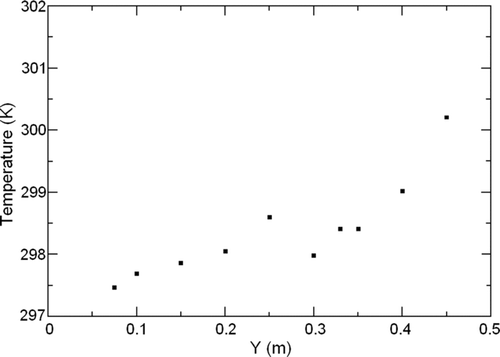
shows the average vertical temperature along the centre of the chamber under displacement ventilation. After gaining heat from the left manikin (the source), the temperature increased rapidly for vertical distances of above 30 cm. The figure also shows clearly the existence of a stratification layer (CitationBrohus and Nielsen 1996).
FIG. 2 Average vertical temperature along the center of the chamber (X = 0.25 m, Y = 0 ∼ 0.5 m, Z = 0.5 m).
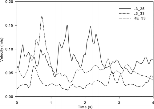
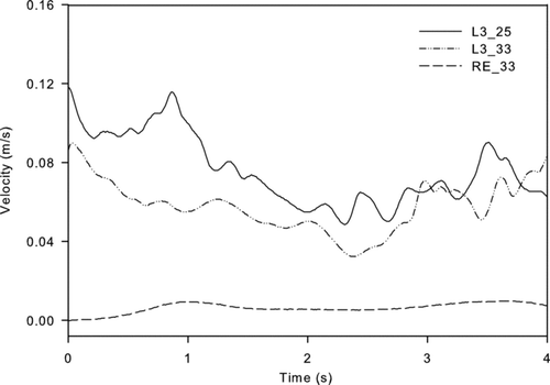
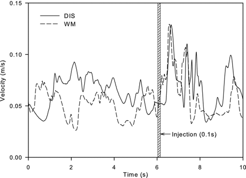
The hot-film anemometry system was used to take velocity measurements at three locations under the two ventilation configurations. The pre-injection results for the MV and DIS schemes are shown in Figures and , respectively, while the results capturing the injection are shown in Figures to 7. Inferring from , the L3_25 position had the highest average velocity, followed by L3_33, and RE_33 had the lowest velocity. For these three locations, the ratio of maximum to minimum average velocity was just 2.8. It can be seen that the velocity was fairly uniform across the locations where measurements were taken. A higher velocity can be observed at the vertical axis along the L3 position. The uniformity of the velocity had a direct impact on the concentration level (detailed later).
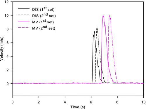
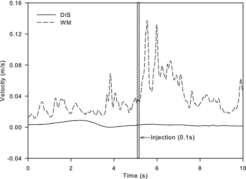
Although the order of the highest to lowest airflow velocity at the three locations was the same under the DIS scheme as for the MV scheme, reveals that the results for the former scheme were quite different. The velocity at RE_33 was at least 10 times lower than the velocity at the two other measuring locations and was approximately 1% of the inlet velocity. In a DIS scheme, the introduction of low air velocity causes minimal induction and mixing (CitationLai and Cheng 2007; ASHRAE 2005). Not only did the air parcel at the RE_33 location receive very little heat, but it was also outside the main airflow pathway. As expected, the average velocity for the three locations in the MV scheme was higher than that for the corresponding points under the DIS scheme. However, regardless of which ventilation system was used, the airflow velocity was low in comparison to the emission velocity shown in . This figure shows two sets of velocity measurements at the midpoint between the two manikins for both ventilation schemes. The emission of PSL particles generated a high-momentum air jet. It is also observed that the spray gun generated very consistent airflow profiles. The peak velocity under the MV scheme was approximately 10 ms–1, while the average of the two measurements taken under the DIS scheme was about 7.9 ms–1, a velocity that represents a high-end expiratory process for the scale of the current setup (CitationChao and Wan 2006; CitationZhu et al. 2006; CitationRichmond-Bryant 2009). The higher velocity measured for the MV scheme is attributed to the higher inlet air velocity used for that scheme: 2 ms–1 vs. 0.4 ms–1 for the DIS scheme.
Inferring from , the pre-emission airflow velocities at L3_25 under both ventilation schemes were comparable to the average values for the DIS and MV schemes (0.067 ms–1 and 0.07 ms–1, respectively). The profiles for the two schemes also resembled each other immediately after the particles were emitted. A comparison of the qualitative concentrations under the two schemes also shows that they were similar (detailed later). The velocity measured at RE_33 during the emission period is shown in . This location was at the rear of the source and was directed away from the injection. One interesting observation made is that the velocity under the well-mixed scheme was very sensitive to the emission of particles, whereas there was no variation in velocity under the displacement scheme when emissions were introduced. This may be caused by the nature of turbulence under a well-mixed system.
One of our objectives was to study how the two ventilation schemes affected spatial and temporal concentration after an expiratory process. Temporal concentration was measured at eight selected points. To facilitate cross-comparison between the two ventilation schemes, the absolute concentration at each location for a particular scheme was made dimensionless by normalizing the peak concentration for that concentration scheme at L3_33. The results are shown in Figures and . Well-mixed ventilation at higher air velocities generally results in more kinetic energy inside the test chamber. For the two selected points (NW_33 and NW_25), the decay rates under the MV scheme were higher than those under the DIS scheme at the same location. This resulted in a lower level of dimensionless concentration under the MV scheme, which also implies that the scheme will lead to higher particle concentration levels in the other regions of the testing chamber in comparison to the DIS. It should be noted that the current decay rates of MV schemes are much higher than the ventilation rate, which was 0.02 s–1. This difference is attributable to the nature of the source. For the study reported here, the particles were carried by a high-momentum airflow generated by the expiratory process. The decay mechanisms included additional diffusion and convection by the high-momentum airflow. A similar explanation can also be put forward for the DIS scheme.
FIG. 8 (a) Particle concentration profiles at EX_33, NW_33, and NW_25 for MV. (b) Particle concentration profiles at L3_25, EX_25, and RE_33 for MV.
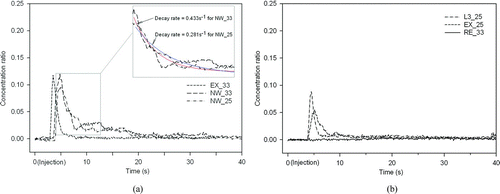
FIG. 9 (a) Particle concentration profiles at EX_33, NW_33, and NW_25 for DIS. (b) Particle concentration profiles at L3_25, EX_25, and RE_33 for DIS.
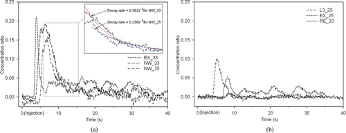
According to the experimental results for the MV scheme, the particles reached the EX_25, NW_25, and L3_25 measuring points at almost the same time after four seconds of injection had elapsed (as shown in Figures and ). They took between 0.4 and 1.6 seconds longer to reach to the corresponding locations under the displacement ventilation scheme. A plausible explanation is that under the displacement ventilation scheme, particles tend to remain at the emission zone level and to move towards the exhaust in a unidirectional flow with thermal stratification. This results in only a few particles being conveyed to the lower zone at a later stage.
Another quantitative measure that can also be used to investigate the effectiveness of the two ventilation systems in removing contaminated particles is transient ventilation effectiveness, ε. It is defined as:
FIG. 10 (a) Transient ventilation effectiveness (ε) and peak-to-peak ratio (PPR) of the measuring positions for MV. (b) Transient ventilation effectiveness (ε) and peak-to-peak ratio (PPR) of the measuring positions for DIS.
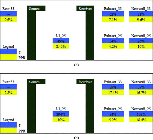
It is also interesting to compare the peak values at different locations. The peak-to-peak ratio was evaluated by the following expression:
Figures and reveal that the DIS scheme provided poorer indoor air quality at locations where the receiver faced the source, particularly in the breathing zone for the standing manikin. The concentration levels measured at EX_33 and NW_33, both of which were in the manikin's breathing zone, were very high. This result implies that under the DIS scheme, the particles emitted traveled a long horizontal distance (i.e., from the source to NW_33). For the sitting position (L3_25), it can be seen that the concentration level and the PPR were both lower than those for EX_33, EX_25, and NW_25, even though the sitting position was closer to the source. For both ventilation schemes, higher concentrations were recorded at EX_33 and NW_33, as most of the particles emitted at a higher velocity reached these two measuring positions. The airflow pattern was easily disturbed by the high momentum airflow, which led to a high level of particle concentration, even at points far from the emission source. These results contradict some previous observations for displacement ventilation systems in which better indoor air quality was reported. The difference is attributed to the differing natures of the emission sources: particle concentrations in convection flows differ from those outside such flows. This observation has also been reported in a prior study (Qian et al. 2006).
The results reported in the extant literature show that the effectiveness of different ventilation systems in removing airborne pollutants remains a controversial topic and that no generalized or conclusive results have been obtained. For conventional ceiling schemes with external pollutant sources, the influence of the high-momentum airflow overwhelms the buoyancy effect and the transport of pollutants is mainly governed by the bulk airflow. Nevertheless, the working principle of displacement ventilation systems is completely reliant on the existence of internal heat sources (i.e., occupancy). Hence, it is very important to compare the ventilation performance of different systems using the same type of pollutant source.
4. Conclusion
The study reported in this paper experimentally investigates the influence of expiratory droplet dispersion under two different ventilation systems. Important parameters, including air temperature, air velocity, temporal concentration, and ventilation effectiveness, were measured both before and after monodisperse particles were emitted. The results show that using a displacement ventilation system does not enhance the mixing of air inside the chamber. However, under the mixing ventilation scheme in which air was supplied at a higher velocity, the airflow pattern was also easily disturbed by the high-momentum jet flow, even at points far from the emission source. It was found that the peak velocity measured for the mixing ventilation system was higher than that observed for the displacement ventilation system at the midpoint between the two manikins after aerosols were emitted. This result was contributed to by the higher inlet air velocity of the mixing ventilation system.
Lower concentration ratios were observed under the mixing ventilation system, in which a higher net air change rate was observed at the measuring locations. This also resulted in higher particle concentration levels in other regions of the chamber in comparison with those measured under the displacement ventilation system. For both ventilation schemes, the particles emitted from the source traveled a long horizontal distance; this indicates a high risk of infection if the receiver is located along the emission path. The results also show that under a displacement ventilation system, emitted particles tend to remain at the emission zone level and to move toward the exhaust in a unidirectional flow with thermal stratification. It was observed that, although the airflow was easily disturbed by the injection of particles at RE_33 under the mixing ventilation system, this had no effect on the measured concentration levels. This finding reveals that the transmission path behavior of particles is different from the behavior of the airflow path. The results also confirm the effective ventilation properties of displacement ventilation systems in light of the higher particle removal efficiency recorded at most of the measuring locations. The upward convective flow generated under schemes of this type plays a significant role in reducing the transport rate of non-buoyant particles from the upper zone to floor level. The transmission of particles depends on the ventilation method used, the distribution of air terminals, the relative location of the source to the receiver, and the existence of the thermal effect (stratification). CitationFlynn et al. (1996) have studied numerical models of how work practices (positions) affect ultimate exposure to massless particles. From both their numerical results and smoke visualization experiments, they concluded that the position of the worker relative to the airflow plays a significant role in determining the exposure level. More experimental studies based on practical scenarios are required before a more effective system that provides for better indoor air quality can be suggested.
The work described in this article was partially supported by a grant from CityU 7002273.
REFERENCES
- ASHRAE . 2005 . “ ASHRAE Handbook-Fundamental ” . Atlanta : American Society of Heating Refrigerating, and Air-Conditioning Engineers .
- Bolster , D. and Linden , P. F. 2009 . Particle Transport in Low Energy Ventilation Systems. Part 2: Transients and Experiments . Indoor Air , 19 : 130 – 144 .
- Brohus , H. and Nielsen , P. V. 1996 . Personal Exposure in Displacement Ventilated Rooms . Indoor Air , 6 : 157 – 167 .
- Berrouk , A. S. , Lai , A. C. K. , Cheung , A. C. T. and Wong , S. L . 2009 . Experimental Measurements and Large Eddy Simulation of Expiratory Droplet Dispersion in a Mechanically Ventilated Enclosure with Thermal Effects . Build. Environ , 45 : 371 – 379 .
- Chao , C. Y. H. and Wan , M. P. 2006 . A Study of the Dispersion of Expiratory Aerosols in Unidirectional Downward and Ceiling-Return Type Airflows Using a Multiphase Approach . Indoor Air , 16 : 296 – 312 .
- Chao , C. Y. H. , Wan , M. P. and Sze To , G. N. 2008 . Transport and Removal of Expiratory Droplets in Hospital Ward Environment . Aerosol Sci. Technol , 42 : 377 – 394 .
- Chen , F. , Yu , S. C. M. and Lai , A. C. K. 2006 . Modeling Particle Distribution and Deposition in Indoor Environments with a New Drift-Flux Model . Atmos. Environ , 40 : 357 – 367 .
- Coffey , C. J. and Hunt , G. R. 2007 . Ventilation Effectiveness Measures Based on Heat Removal: Part 1. Definitions . Build. Environ , 42 : 2241 – 2248 .
- Friberg , B. , Friberg , S. , Burman , L. G. , Lundholm , R. and Ostensson , R. 1996 . Inefficiency of Upward Displacement Operating Theatre Ventilation . J. Hosp. Infect , 33 : 263 – 272 .
- Flynn , M. R. , Lackey , B. D. and Muthedath , P. 1996 . Experimental and Numerical Studies on the Impact of Work Practices Used to Control Exposures . Amer. Indust. Hyg. Assoc. J , 57 : 469 – 475 .
- Gao , N. and Niu , J. L. 2006 . Transient CFD Simulation of the Respiration Process and Inter-Person Exposure Assessment . Build. Environ , 41 : 1214 – 1222 .
- Huang , J.-M. and Tsao , S.-M . 2005 . The Influence of Air Motion on Bacteria Removal in Negative Pressure Rooms . HVAC and R Res. , 11 : 563 – 585 .
- Lai , A. C. K. and Cheng , Y. C. 2007 . Study of Expiratory Droplet Dispersion and Transport Using a New Eulerian Modeling Approach . Atmos. Environ , 41 : 7473 – 7484 .
- Lau , J. and Chen , Q. 2006 . Energy Analysis for Workshops with Floor-Supply Displacement Ventilation under the U.S. Climates . Energy and Build , 38 : 1212 – 1219 .
- Olsen , E. L. and Chen , Q. 2003 . Energy Consumption and Comfort Analysis for Different Low-Energy Cooling Systems in a Mild Climate . Energy and Build , 35 : 561 – 571 .
- Qian , H. , Li , Y. , Nielsen , P. V. and Hyldgaard , C. E. 2008 . Dispersion of Exhalation Pollutants in a Two-Bed Hospital Ward with a Downward Ventilation System . Build. Environ , 43 : 344 – 354 .
- Richmond-Bryant , J. 2009 . Transport of Exhaled Particulate Matter in Airborne Infection Isolation Rooms . Build. Environ , 44 : 44 – 55 .
- Wan , M. P. and Chao , C. Y. H. 2007 . Transport Characteristics of Expiratory Droplets and Droplet Nuclei in Indoor Environments with Different Ventilation Air Flow Patterns . J. Biomech. Engineer.—Trans. ASME , 129 : 341 – 353 .
- Wan , M. P. , Sze To , G. N. , Chao , C. Y. H. , Fang , L. and Melikov , A. K. 2009 . Modeling the Fate of Expiratory Aerosols and the Associated Infection Risk in an Aircraft Cabin Environment . Aerosol Sci. Technol , 43 : 322 – 343 .
- Wells , W. F. 1955 . Airborne Contagion and Air Hygiene , Cambridge, MA : Harvard University Press .
- Zhang , Z. and Chen , Q. 2006 . Experimental Measurements and Numerical Simulations of Particle Transport and Distribution in Ventilated Rooms . Atmos. Environ , 40 : 3396 – 3408 .
- Zhang , Z. and Chen , Q. 2007 . Comparison of the Eulerian and Lagrangian Methods for Predicting Particle Transport in Enclosed Spaces . Atmos. Environ , 41 : 5236 – 5248 .
- Zhang , Z. , Chen , X. , Mazumdar , S. , Zhang , T. and Chen , Q. 2009 . Experimental and Numerical Investigation of Airflow and Contaminant Transport in an Airliner Cabin Mockup . Build. Environ , 44 : 85 – 94 .
- Zhao , B. , Zhang , Y. , Li , X. , Yang , X. and Huang , D. 2004 . Comparison of Indoor Aerosol Particle Concentration and Deposition in Different Ventilated Rooms by Numerical Method . Build. Environ , 39 : 1 – 8 .
- Zhao , B. , Yang , C. , Chen , C. , Feng , C. , Yang , X. , Sun , L. , Gong , W. and Yu , L. 2009 . How Many Airborne Particles Emitted from a Nurse will Reach the Breathing Zone/Body Surface of the Patient in ISO Class-5 Single-Bed Hospital Protective Environments? A Numerical Analysis . Aerosol Sci. Technol , 43 : 990 – 1005 .
- Zhu , S. , Kato , S. and Yang , J.-H . 2006 . Study on Transport Characteristics of Saliva Droplets Produced by Coughing in a Calm Environment . Build. Environ , 12 : 1691 – 1702 .
