Abstract
An improved Eulerian model is proposed to predict particle deposition velocity in a typical mechanical ventilation system of a dairy food factory. For fully developed turbulent flow, the model is modified based on the three-layer model developed by CitationZhao and Wu (2006a), accounting for thermophoresis as well as turbophoresis, Brownian diffusion, turbulent diffusion, and gravitational settling. Based on in-situ measurements of the aerosol size distributions, particles discussed in this article were in the size range 0.3–20 μm. The measured mass concentration and the predicted particle deposition velocity were used to calculate the deposited particle mass flux in the ventilation duct. The results indicate that the effects of temperature gradients and of surface roughness should be considered in food factories ventilation ducts. For horizontal surfaces, it is shown that even a little difference between empirical and theoretical models can lead to a 2-fold difference in the predicted deposited particle mass flux. Findings of this work may help to identify the specific parameters for cleaning procedures.
1. INTRODUCTION
In recent years, the investigations concerning ventilation in the agro-food industry mostly look at the air distribution but very poor attention was paid to the ventilation duct systems. However, the control of the indoor air quality is directly related to the particle deposition in the ventilation ducts. Deposition onto duct surfaces may affect the microbial quality of the air in forced-ventilation food plants. Depending on the amount of dirt, the material, and the environmental conditions, the HVAC (heating, ventilation, and air-conditioning) system may become an active growth site for microorganisms and a source of biological contamination (CitationFoarde and Menetrez 2002). As mentioned by CitationZhao and Wu (2006a) a number of problems associated with human health are caused by the pollution of ventilation ducts. CitationKozak et al. (1996) suggested that the presence of Listeria monocytogenes in finished product must be the result of post-pasteurization contamination from an HVAC system. CitationByrne et al. (2008) studied the airborne contamination in a pork processing plant and indicated that the contamination could be attributed to people in the area, condensation and mechanically generated aerosol, but they also mentioned that building ventilation factors would also need to be considered before a definite conclusion could be made. According to a study by CitationSiegel and Nazaroff (2003), air turbulence in the duct leading up to a heat exchanger can induce deposition on heat exchanger surfaces. In dairy processing, this may reduce the processing efficiency, since the deposited material disturbs both the fluid flow and the heat transfer, and impair the product quality (CitationPetermeier et al. 2002). Ventilation duct systems usually consist in very large cross section duct with branches, bends, reductions, and diverging sections. All of these elements which cause a flow perturbation and affect the nature of the turbulence are likely to have an influence on the deposition rate (CitationMiguel et al. 2004; CitationSippola and Nazaroff 2005).
To meet the code of ventilation duct cleanness, the HVAC unit and ductwork should be cleaned on a periodic basis (CitationZhao and Chen 2006). Thus, the ability to predict the deposited particle mass flux (DMF) within ventilation ducts will help identify the specific parameters for cleaning procedures that are generally effective in reducing microbial contamination.
Recently, CitationZhao and Wu (2006a) proposed an improved model based on the three-layer model by CitationLai and Nazaroff (2000), accounting for turbophoresis as well as Brownian diffusion, turbulent diffusion, and gravitational settling. The agreement between improved model results and measured data collected by CitationSippola and Nazaroff (2004) in uninsulated steel and internally insulated ducts is acceptable for vertical and horizontal surfaces (CitationZhao and Wu 2006a). However, in food factories, temperature could considerably change between workshops. CitationZhao et al. (2009) suggested that when the size of the particles gets smaller and smaller, the effect of thermophoresis force becomes stronger while the effect of gravity drops. Besides, the thermophoretic mechanism for larger particles is subjected to the air slipping along the nonuniformly heated particle surface, where the nonuniformity is stipulated by the air temperature gradient and strongly depends on the thermal conductivity of particles (CitationBakanov 1991, CitationTsai 1999). Therefore, thermophoretic particle deposition needs to be considered carefully to get reasonable results.
In the frame of the national project CLEANAIRNET, the hygienic design of ventilation ducts in food factories is studied. The main purpose of this article is to modify the three-layer model for particle deposition by taking thermophoresis into account for predicting particle deposition in a typical ventilation duct of a food factory. To this end we have sought also to quantify the effects of various factors that may contribute to the particle deposition flux. After comparison of predicted deposition velocity with empirical model (CitationSippola and Nazaroff 2003) and measured data collected by CitationSippola and Nazaroff (2004), our model and the empirical model are applied to predict the DMF based on in-situ measured physical parameters (flow conditions and particle mass concentration).
2. MODEL DESCRIPTION
2.1. Particle Deposition Flux
For fully developed flow, CitationZhao and Wu (2006a) proposed a three-layer model by considering turbophoresis as well as Brownian diffusion, turbulent diffusion, and gravitational settling. In this Eulerian model, the particle flux within the boundary layer is assumed to be one-dimensional, steady, and constant, i.e., there are no sources of particles. To model the thermophoresis as a mechanism of particle deposition, the particle flux should be modified as follows:
For spherical particles, the Brownian diffusivity D B can be calculated by the Stokes-Einstein relation, corrected for slip:
Here, T is the fluid absolute temperature, σ B = 1.38× 10− 23 J/K is the Boltzmann constant, d p is the physical diameter, μ is the dynamic viscosity of the air, and C c is the Cunningham coefficient caused by slippage (CitationHinds 1998):
The thermophoretic velocity v ther is given by the following equation:
For rough surfaces, according to CitationZhao and Wu (2006b) the wall boundary condition y 0 + is evaluated at:
In Equation (Equation7), the fluid friction velocity is calculated by:
A balance of the drag force with the gravitational force on a particle leads to a simple expression for the particle gravitational settling velocity:
The turbophoretic velocity is given as (CitationCaporaloni et al. 1975):
2.2. Particle Deposition Velocity
The deposition velocity V d (m s− 1) is the total particle flux J normalized by the time-averaged particle concentration C ∞ (μ gm− 3) in the center line duct:
To solve the model, Equation (Equation21) can be integrated from the duct wally 0 +, where C + = 0, to the turbulent core y + = 200, where C + = 1. With these boundary conditions, the solution of Equation (Equation21) is as follows (CitationZhao and Wu 2006a):
3. RESULTS AND DISCUSSION
3.1. Case Study Description
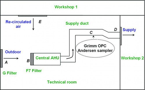
To study the influence of the different mechanisms on particle deposition in a typical food factory ventilation system, the above model requires several input parameters, such as flow conditions, particle mass concentration and characteristics of the ventilation duct. These parameters were obtained by one partner (Cemagref) in the project CLEANAIRNET from in-situ measurements. Part of these data is still confidential, but some useful information is available. shows a schematic diagram of this industrial ventilation system. All supply ducts having diameter φ of 355 mm are galvanized steel and are not insulated. The microscale roughness, k, of the galvanized steel ducts is estimated to be in the range 6–60 μ m. Outdoor air, together with a proportion of the air returned from the air-conditioned workshops (re-circulated air) is drawn into a central air handling unit (AHU). This mixed air is cleaned by means of two types of filters; the G filter and F filter with a 40% and 85% ASHRAE dust spot average efficiency, respectively. The mean air velocity U ∞ at the centerline of the supply duct is equal to 5.4 ± 0.1 m.s−1, giving a Reynolds number of 1.3× 10⁵. The central AHU delivers air at the temperature and the relative humidity close to 20°C and 20%, respectively.
During this study, temperature was also measured at locations A, B, C, and D within the technical room. The measured temperature difference between the air in the supply duct and the air in the technical room was in the range 0–10°C and it depends largely on seasonal temperature variability.
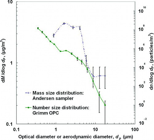
Optical particle counter (Grimm OPC, Model 1.108) and cascade impactor (Andersen sampler) were used to measure the mass- and number-size distributions of aerosols, at an air-flow rate of 1.2 L/min and 22 L/min, for 648 and 672 h, respectively. Thus, the Grimm OPC recorded a particle number concentration size distribution every 5 s. Two isokinetic probes were used to sample the aerosol, at a close location in the supply duct (point C in ). The corresponding mass and number concentrations of the aerosol particles in different size ranges are given in and , where the number concentration is calculated from the average weekly number concentration. Hence, the particles that will be discussed in this article are in the size range 0.3–20 μ m.
TABLE 1 The measured mass concentration for different stages of the Andersen sampler
TABLE 2 The measured particle concentration by the Grimm OPC
The measured size distributions can be presented through a differential plot between dM/dlog d p (dn/dlogd p ) and d p , which shows the modes of particle size distribution as well as the amount of sample which is found in each size range along a continuous spectrum. To provide a better presentation of the distribution of mass concentration of particles in the size interval from 7 to 20 μ m, we assumed that the relative concentration is constant (i.e., dM/dlogd p = 0.614 μ g/m3) for the size ranges of particles: 7–10.5, 10.5–15, and 15–20 μ m.
shows a comparison between the mass- and number-size distributions of aerosols computed from the samples collected using Andersen sampler and Grimm OPC. The mass size spectra show bi-modal distribution with a mode around 1.6 μ m and second mode around 4.0 μ m. Generally, aerosols of coarse sizes originate from the nature of the product and processing activities (i.e., mechanical operations). Finding coarse particles after F filter could be considered as not acceptable. Nevertheless, this observation is not unusual in real industrial conditions. In fact, many common HVAC filters are partially efficient for particle sizes less than 10 μ m (CitationHanley et al. 1994). Moreover, the bypass of air around filters has been observed, but rarely quantified (CitationSippola 2002).
The visual inspection of the inside of the ducts showed that the upward-facing surfaces were covered with heavy milk powder deposits. The deposition rates in side-facing surfaces and downward-facing surfaces are nearly the same and less important than those in upward-facing surfaces. This is metabolically favorable for microorganisms to attach to surfaces, replicate themselves and biofilm formation, as nutrients are more concentrated at an interface. The consequences of biofilm communities forming in food processing environments are substantial (CitationBower et al. 1996).
3.2. Mechanisms and Parameters Affecting Particle Deposition
The above measurements and corresponding parameters (u* = 0.25 m.s− 1, 0.1 < k + < 1 and 0 < Δ T < 10) were introduced in the present model to predict particle deposition velocity in ventilation ducts of this dairy factory. The results are presented for particle deposition from fully developed turbulent pipe flow. The analysis is restricted to dilute suspensions meaning that the fluid motion is unaffected by the presence of the particles and that particle–particle collisions can be neglected. From the above description, the calculations were performed for spherical particles of milk powder with the fixed values of particle density ρ p = 700 kg.m− 3 and thermal conductivity k p = 0.06 Wm− 1K− 1 (CitationChong and Chen 1999; CitationMacCarthy 1985). Air parameters were taken at standard conditions of ρ a = 1.2 kg.m− 3, C p = 1004 J.kg− 1K− 1, μ = 1.8× 10− 5 Pa.s, λ = 0.07 μ m, and k a = 0.026 Wm− 1K− 1.
presents the variation of the nondimensional deposition velocity as a function of particle diameter for different mechanisms. Equations (Equation22)–(Equation23) are solved for isothermal flow, with k + = 0.1 (k = 6 μ m). The molecular and turbulent diffusion effect is calculated by assuming that turbulence is homogeneous. In this case, Equation (Equation23) is solved by taking the lower boundary at y 0 + = 0, with i = 0. Similar to previous studies, the deposition velocity monotonically decreases with increasing particle diameter.
FIG. 3 Comparison of the dimensionless deposition velocity for different mechanisms. For all computed curves, k + = 0.1, u* = 0.25 m.s−1, and Δ T = 0.
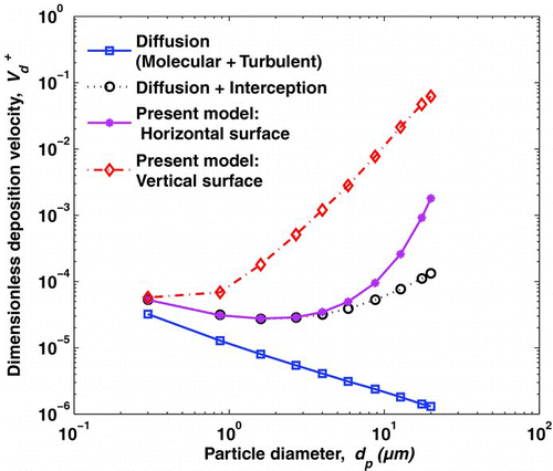
Including interception effect changes the behavior of the deposition velocity. When the lower boundary is given by Equation (Equation7) with k + = 0.1, the calculated deposition velocity increases substantially with increasing particle diameter.
In , total deposition for vertical surface is calculated by retaining all terms in Equation (Equation22), with i = 0. It merges with the “diffusion + interception” case for very small particles. For particles ranging from 4 to 20 μ m, the turbulent eddy fluctuations effect becomes important, and the deposition rate increases sharply as the particle diameter increases further (CitationZhao and Wu 2006b).
Line predicting total particle deposition for horizontal surface is also included in . Equation (Equation22) is now calculated with i = 1.When the particle diameter is large enough, the gravitational sedimentation strongly affects the motion of particles and controls the particle deposition much more than diffusion and turbophoresis effect.
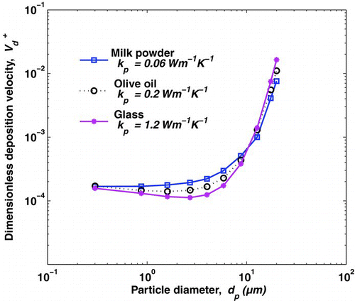
shows the results of calculations where all transport mechanisms, have been included (Equation (Equation22)). Four cases are considered: Δ T = 0, Δ T = 1 K, Δ T = 5 K, and Δ T = 10 K. For horizontal surfaces, thermophoresis would tend to increase deposition of particles less than 3 μ m in diameter. For vertical surfaces, the effect of thermophoresis is significant over the entire range of particle sizes. demonstrated that for vertical surfaces, the significant role of thermophoresis in enhancing particle deposition rates is especially effective for particles with a size of 0.3 μ m ≤ d p ≤ 10μ m. These results corroborate calculations performed by CitationTsai and Lin (1999). From the plot (), when Δ T = 10 K, one can see that the deposition rate of particles less than 10 μ m in diameter increases by approximately one order of magnitude. In addition, thermal conductivity and particle density can affect thermophoretic deposition. Thus, in we show the comparison of dimensionless deposition velocity onto vertical wall at three thermal conductivities of particles and for Δ T = 5°C. For particles with a size of 0.875 ≤ d p ≤ 5.85μ m, the model predicts a greater thermophoretic deposition rate of low conductive particles and proves the importance of this parameter in predicting particle deposition flux.
FIG. 4 Effects of thermal diffusion on the predicted deposition rate for (a) horizontal and (b) vertical. For all computed curves, k + = 0.1, u* = 0.25 m.s−1, and k p = 0.06 W.K−1.m−1.
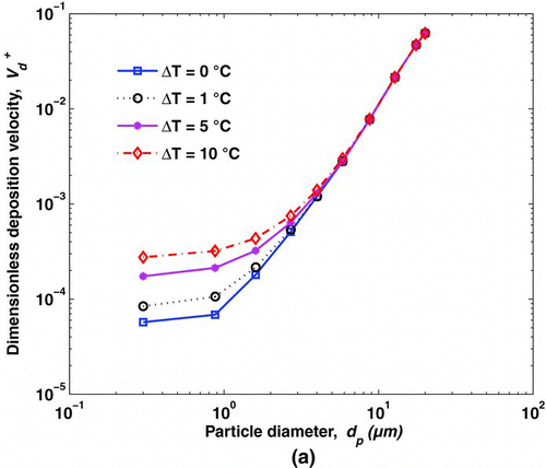
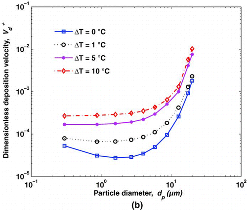
FIG. 5 Comparison of predicted deposition velocity at three thermal conductivities of particles. For all computed curves, k + = 0.1, u* = 0.25 m.s−1, Δ T = 5°C, and ρ p is equal to 700, 920, and 1200 for Milk powder, Olive oil, and Glass, respectively.
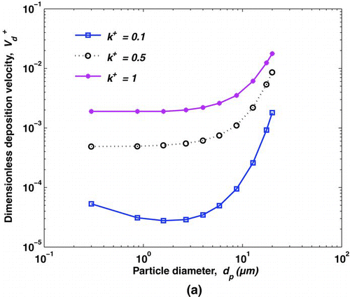
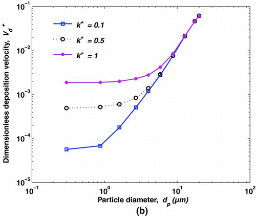
illustrates the variation in total deposition velocity with particle diameter for horizontal surface and different roughness parameters: k + = 0.1, k + = 0.5, and k + = 1, which correspond to roughnesses k = 6, 30, and 60 μ m. Equations (Equation22)–(Equation23) are solved for isothermal flow. The calculations show that the presence of small surface roughness significantly enhances deposition especially of small particles. When k + = 1, the deposition velocity of 2 μ m particles varies by approximately two orders and one order of magnitude for vertical and horizontal surfaces, respectively.
FIG. 6 Effects of surface roughness on the predicted deposition rate for (a) vertical and (b) horizontal surfaces. For all computed curves, Δ T = 0 and u* = 0.25 m.s−1.
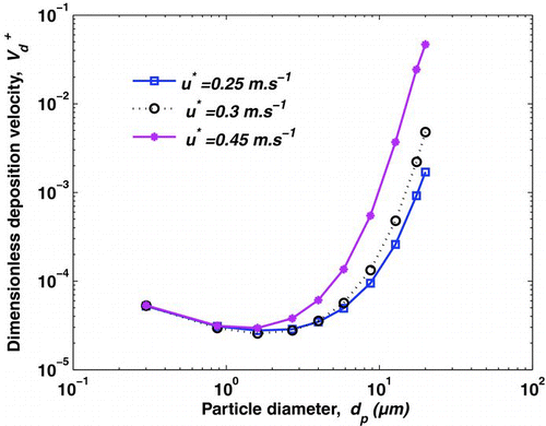
The use of expressions validated only for fully developed turbulent flow seems to be the main drawback of theoretical models. For example, the friction velocity is a major parameter which determination was obtained by a simplified approach (Equation (Equation9)). To illustrate its influence, we performed calculations of the dimensionless deposition velocity onto vertical wall for three friction velocities (). Equations (Equation22)–(Equation23) are solved for isothermal flow with k + = 0.1. For submicron particles, the dimensionless deposition velocities are nearly the same. The reason is that the effect of turbophoresis on particle deposition is far less than that of Brownian diffusion in this range of particle diameters (CitationZhao and Wu 2006a). For larger particles, dimensionless deposition velocities are highly dependent on the magnitude of the friction velocity. Besides, the friction velocity indicates the level of turbulence in the flow and the degree to which particles may be transported and deposited to walls by turbulent fluctuations. Thus, for accurate evaluation of the deposition rate, this parameter needs to be properly modeled.
3.3. Comparison Between Models
Experiments using real HVAC materials for the evaluation of the deposition velocity are rare. As this study considers real ventilation duct, the only available measured data that could be used to validate the present model are those of CitationSippola and Nazaroff (2004). shows the comparison of the predicted deposition velocity with empirical model (CitationSippola and Nazaroff 2003) and measured data collected by CitationSippola and Nazaroff (2004) for vertical and horizontal surfaces. Here, Equations (Equation22)–(Equation23) are solved based on experimental parameters (CitationSippola 2002); k = 5 μ m, u* = 0.27 m/s, and Δ T = 0.4°C. It could be firstly mentioned that predicted deposition rates from empirical equations do not perfectly follow the trends established by the experimental data. These equations have the drawback that they cannot account for changes in the microscale roughness character of the ducts. In engineering practice, usually more than one mechanism can act simultaneously and their interactions must be considered for the accurate prediction of deposition rates. As the accuracy of the measurement data was within ± 12%, the predicted results by the present model agree well with the measured data, for horizontal surfaces owing to the influence of gravity on large particles. shows that a small temperature gradient (Δ T = 0.4°C) produces a better agreement between the prediction and the experimental data.
FIG. 8 Comparison of predicted results by the present model with the empirical model and measured data collected by CitationSippola and Nazaroff (2004) for (a) horizontal and (b) vertical surfaces.
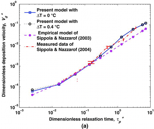
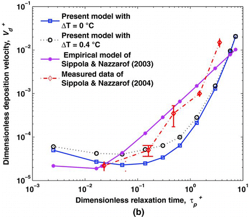
These results confirm that developing theoretical models is still a promising way to predict the deposition velocity. Improvements of these models would probably come from a better consideration of turbulence and friction velocity.
3.4. Predicting Particle Deposition Flux
The present model and empirical models were applied to predict the DMF at vertical and horizontal surfaces of the ventilation ducts of the dairy food factory.
shows the DMF (μ g/m2.year) at vertical and horizontal surfaces calculated by theoretical and empirical models for different mean particle diameters. Values of the DMF were calculated using Equation (Equation19), where the values of C ∞ are the measured and estimated (i.e., in the range 7–20 μ m) mass concentration. Here, the theoretical values of V d are calculated using Equations (Equation22)–(Equation23) for Δ T = 0.4°C, k = 5 μ m, and u* = 0.25 m/s. The predicted results of the total DMF at vertical and horizontal surfaces are given in .
FIG. 9 Comparison of deposited particle mass flux for the present model and empirical models at (a) horizontal and (b) vertical surfaces.
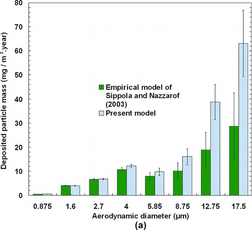
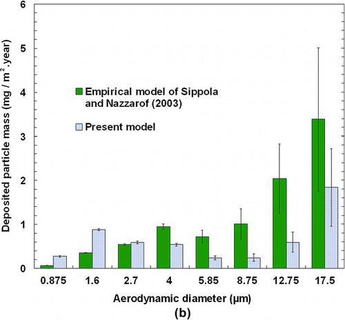
TABLE 3 The predicted results of total deposited particle mass in vertical and horizontal surfaces
For the same reason mentioned above, indicates a discrepancy between theoretical and empirical models. Using the present model, for super-micron particles, the DMF at the floor is about 6 to 60 times larger than that at vertical walls. For each particle size, the empirical model predicts the DMF at the floor about 5–12 times larger than that at vertical walls. Thus, the deposited particle mass on the floor is sufficient to check if a ventilation duct should be cleaned.
Despite the high mass concentration of small particles (d p < 5 μ m), the corresponding values of the DMF are significantly smaller than that predicted for larger particles. As discussed above, the gravitational settling velocity is dominant, for most of the particle sizes studied here, and can vary over a few orders of magnitudes (). This also explains why the DMF increases with increasing particle diameter, as shown in .
In , for particles diameter less than 8.75 μ m, the maximum DMF was obtained with the present model for the 1.6 μ m diameter particles. As the deposition velocity is quite constant in the range 0.65 to 8.75 μ m, the deposition is controlled by the mass concentration distribution. For particles larger than 8.75 μ m, the DMF increased with the diameter owing to the turbophoretic effect.
Errors occurring in the prediction of the deposition velocity would significantly alter the accuracy in predicting the particle accumulation by deposition in ventilation duct. Thereby, the total DMF predicted by the present model is two times larger at horizontal surfaces, and two times less at vertical walls than that predicted by empirical model ().
Ventilation systems can be potential sources of pollutants and contamination due to the accumulation of particles in their duct ventilation. Ventilation systems must therefore be maintained under optimal cleanliness conditions. According to CitationLavoie et al. (2007), the established cleaning initiation criteria correspond to 300 mg/m2 for the ASPEC method (ASPEC, French association for the prevention and study of contamination). We can therefore state that the particle accumulation in a typical ventilation duct of a food factory would take approximately two years to meet the cleaning code. However, particles films on duct surfaces may enhance the interception and electrostatic effects, owing to microscale morphological changes in the surface. This should increase the particle deposition rates and advance the cleaning time.
4. CONCLUSION
In the Agro-food industry, heating, ventilation, and air conditioning (HVAC) systems are often used to limit worker and food product exposure to airborne particles by removing contaminated air. However, HVAC systems have proved to be a source of contamination with pathogenic microorganisms. In order to prevent contamination, proper attention must be paid to determine particle deposition rates in ventilation ducts and to determine the best methods for predicting these rates. Based on the presented results, the following conclusions may be drawn:
-
Thermophoresis may play an important role on the deposition rate of coarse particles for non-isothermal cases. In dairy industry, the low thermal conductivity of milk powder increases the thermophoretic deposition.
-
Calculations confirm that the presence of small surface roughness significantly enhances deposition of small particles. The micro topography of a surface can also complicate the cleaning process as crevices and other surface imperfections can shield attached cells from the rigors of cleaning.
-
The predicted total deposited mass flux to the floor (upward wall) is about 30 times larger than that onto vertical walls. In this case, the most deposited particle mass is associated with the coarse particles, which was determined by the nature of the product (milk powder) and the industrial operations.
At present, empirical and theoretical models can not reliably be applied to predict accumulation rates of particle deposits in ducts. For the purpose of studying the particle deposition in ventilation ducts by theoretical models, knowledge on roughness structure, temperature gradient, flow characteristics need to be further investigated. Thus, new experiments will be performed in laboratory at real scale with HVAC materials. In addition, computational fluid dynamics (CFD) will be adopted to better analyze turbulence and to determine the friction velocity.
This research was carried out with financial support from the ANR (Agence Nationale de la Recherche) for the specific programme “Programme National de Recherche en Alimentation et nutrition humaine,” project CLEANAIRNET “Hygienic design of ventilation duct systems in food factories,” in which nine partners are involved: Adria Normandie, Cemagref, CERTES, Clauger, CSTB, GEPEA, Lactalis R&D, Laval Mayenne Technopôle, and Soredab.
REFERENCES
- Bakanov , S. P. 1991 . Thermophoresis in Gases at Small Knudsen Numbers . Aerosol Sci. Technol. , 15 : 77 – 92 .
- Baron , P. A. and Willeke , K. 2005 . Aerosol Measurement: Principles, Techniques, and Applications, , 2nd ed. , New York : Wiley .
- Bower , C. K. , McGuire , J. and Daeschel , M. A. 1996 . The Adhesion and Detachment of Bacteria and Spores on Food-Contact Surfaces . J. Trends in Food Sci. Technol. , 71 : 152 – 157 .
- Byrne , B. , Lyng , J. , Dunne , G. and Bolton , D. J. 2008 . An Assessment of the Microbial Quality of the Air within a Pork Processing Plant . Food Control , 19 : 915 – 920 .
- Caporaloni , M. , Tampieri , F , Trombetti , F. and Vittori , O. 1975 . Transfer of Particles in Nonisotropic Air Turbulence . J. Atmos. Sci. , 32 : 565 – 568 .
- Chong , L. V. and Chen , X. D. 1999 . A Mathematical Model of the Self-Heating of Spray-Dried Food Powders Containing Fat, Protein, Sugar and Moisture . Chem. Engineer. Sci , 54 : 4165 – 4178 .
- Davies , C. N. 1966 . “ Deposition from Moving Aerosols ” . In Aerosol Science , 393 – 446 . London : Academic Press .
- Foarde , K. K. and Menetrez , M. Y. 2002 . Evaluating the Potential Efficacy of Three Antifungal Sealants of Duct Liner and Galvanized Steel as Used in HVAC Systems . J. Indust. Microbiol. & Biotechnol. , 29 : 38 – 43 .
- Guha , A. 1997 . A Unified Eulerian Theory of Turbulent Deposition to Smooth and Rough Surfaces . J. Aerosol Sci. , 28 : 1517 – 1537 .
- Hanley , J. T. , Ensor , D. S. , Smith , D. D. and Sparks , L. E. 1994 . Fractional Aerosol Filtration Efficiency of In-Duct Ventilation Air Cleaners . Indoor Air , 4 : 169 – 178 .
- Hinds , W. C. 1998 . Aerosol Technology , New York : Wiley–Interscience .
- Johansen , S. T. 1991 . The Deposition of Particles on Vertical Walls . Intl. J. Multiphase Flow , 17 : 355 – 376 .
- Kozak , J. , Balmer , T. , Byrne , R. and Fisher , K. 1996 . Prevalence of Listeria Monocytogenes in Foods: Incidence in Dairy Products . J. Food Control , 7 ( 415 ) : 215 – 221 .
- Lai , A. C. K. and Nazaroff , W. W. 2000 . Modeling Indoor Particle Deposition from Turbulent Flow onto Smooth Surfaces . J. Aerosol Sci. , 31 : 463 – 476 .
- Lavoie , J. , Bahloul , A. , Cloutier , Y. and Gravel , R. Cleaning Initiation Criteria for Heating, Ventilation and Air Conditioning (HVAC) Systems in Non-Industrial Buildings . Proceedings of Clima 2007 . June 10–14 2007 , Helsinki, Finland. Vol. 3 , pp. 273 – 280 .
- MacCarthy , D. A. 1985 . Effect of Temperature and Bulk Density on Thermal Conductivity of Spray-Dried Whole Milk Powder . J. Food Engineer. , 4 : 249 – 263 .
- Miguel , A. F. , Reis , A. and Aydina , M. 2004 . Aerosol Particle Deposition and Distribution in Bifurcating Ventilation Ducts . J. Haz. Mat. , B116 : 249 – 255 .
- Nerisson , P. 2009 . Modélisation Du Transfert Des Aérosols Dans un Local Ventilé , Ph.D. Dissertation University of Toulouse .
- Petermeier , H. , Benning , R. , Delgado , A. , Kulozik , U. , Hinrichs , J. and Becker , T. 2002 . Hybrid Model of the Fouling Process in Tubular Heat Exchangers for the Dairy Industry . J. Food Engineer. , 55 ( 1 ) : 9 – 17 .
- Sippola , M. R. and Nazaroff , W. W. 2003 . Modeling Particle Loss in Ventilation Ducts . Atmos. Environ. , 37 : 5597 – 5609 .
- Sippola , M. R. and Nazaroff , W. W. 2004 . Experiments Measuring Particle Deposition from Fully Developed Turbulent Flow in Ventilation Ducts . Aerosol Sci. Technol. , 38 : 914 – 925 .
- Sippola , M. R. and Nazaroff , W. W. 2005 . Particle Deposition in Ventilation Ducts: Connectors, Bends and Developing Turbulent Flow . Aerosol Sci. Technol. , 39 : 139 – 150 .
- Sippola , M. R. 2002 . Particle Deposition in Ventilation Ducts , Ph.D. Dissertation Berkeley : University of California .
- Siegel , J. A. and Nazaroff , W. W. 2003 . Predicting Particle Deposition on HVAC Heat Exchangers . Atmos. Environ. , 37 : 5587 – 96 .
- Talbot , L. , Cheng , R. K. , Schefer , R. W. and Willis , D. R. 1980 . Thermophoresis of Particles in a Heated Boundary Layer . J. Fluid Mechan. , 101 ( 4 ) : 737 – 758 .
- Tsai , R. and Lin , Z. Y. 1999 . An Approach for Evaluating Aerosol Particle Deposition from a Natural Convection Flow onto a Vertical Flat Plate . J. Haz. Mat. , B69 : 217 – 227 .
- White , F. M. 1986 . Fluid Mechanics, , 2nd ed , New York : McGraw-Hill .
- Zhao , B. and Wu , J. 2006a . Modeling Particle Deposition from Fully Developed Turbulent Flow in Ventilation Duct . Atmos. Environ. , 40 : 457 – 466 .
- Zhao , B. and Wu , J. 2006b . Modeling Particle Deposition onto Rough Walls in Ventilation Duct . Atmos. Environ. , 40 : 6918 – 6927 .
- Zhao , B. and Chen , J. 2006 . Numerical Analysis of Particle Deposition in Ventilation Duct. Build . Environ. , 41 : 710 – 718 .
- Zhao , B. , Chen , C. and Tan , Z. 2009 . Modeling of Ultrafine Particle Dispersion in Indoor Environments with an Improved Drift Flux Model . J. Aerosol Sci. , 40 : 29 – 43 .
