Abstract
Three-dimensional, incompressible turbulent air-particle flows in a channel with a temperature gradient are simulated by direct numerical simulations (DNS). The calculations used the fractional projection method to directly solve the Navier-Stokes equations. For obtaining more accurate results, the Oberbeck-Boussinesq model was used for considering the convective heat transfer and applied two-way coupling between the particles and the air phase to accurately simulate flow field state. The particles motions including mutual collisions were calculated with the direct simulation Monte-Carlo method (DSMC). The particles agglomeration and deposition in the turbulent channel flow with a temperature gradient were simulated by the Dahneke model. The research focused on the effects of the Reynolds number, the temperature gradient and particle concentration which simultaneity affect particle kinematics, impacts, agglomerations, and deposition characteristics. The numerical results show that the thermophoresis dominates the particle deposition, which agrees well with the experimental data, the particle concentration determines the particle collision and agglomeration rate, the Reynolds number determines the particle distribution in the duct and the 2.5 μm particles do not obviously affect the air phase motion under comparatively low concentration referred in this research.
Nomenclature
| A | = |
Hamaker constant (J) |
| CD | = |
the drag coefficient |
| Cp | = |
specific heat capacity at constant pressure (J·kg−1·K−1) |
| d | = |
particle diameter (m) |
| e | = |
the coefficient of restitution |
| FD | = |
the drag force (N) |
| Gr | = |
the Grashof number |
| g | = |
acceleration of gravity (m·s−2) |
| m | = |
particle quality (kg) |
| P | = |
air pressure (Pa) |
| Pr | = |
the Prandtl number |
| Ra | = |
the Rayleigh number |
| Re | = |
the Reynolds number |
| S | = |
the particle frontal area (m2) |
| T | = |
temperature (K) |
| t | = |
time (s) |
| u | = |
velocity (m·s−1) |
| V | = |
Particle relatively velocity |
| Vp | = |
Particle Poisson's ratio |
| V* | = |
the capture limit velocity (m·s−1) |
| x | = |
Cartesian coordinate (m) |
| Y | = |
Particle Young's modulus |
| y | = |
Cartesian coordinate (m) |
| z | = |
Cartesian coordinate (m) |
Greek Symbols
| δ | = |
half width of the channel (m) |
| δ0 | = |
the distance between the two particles (m) |
| ρ | = |
density (kg·m−3) |
| ΔE | = |
the particle-surface adhesion energy (J) |
| μ | = |
fluid viscosity (Pa·s) |
| ν | = |
kinematics fluid viscosity (m−2·s−1) |
Subscripts
| e | = |
inlet |
| f | = |
fluid |
| p | = |
particle |
| r | = |
relative |
| w | = |
wall |
1. INTRODUCTION
In recent years, inhalable particle emissions produced by coal/oil combustion have induced serious environmental pollution (CitationMorawska and Zhang 2002). One effective method to control particulate matter (PM) emissions from coal/oil combustion is to use thermophoresis to remove particles (CitationMesserer et al. 2003; CitationZhou et al. 2005).
Experimental and theoretical studies on thermophoretic particle deposition in turbulent channel flows (CitationMorawska et al. 2002; CitationByers and Calvert 1969; CitationRomay et al. 1998; CitationBatchelor and Shen 1985; CitationWood 1981) have been reported. The available experimental results indicate that the particle deposition mechanisms are quite complicated under turbulent flow conditions. Some investigators found from experiments that the particle deposition in the turbulent flow conditions was caused by thermophoresis alone and the turbulent diffusion was not a significant factor (CitationByers et al. 1969). But, some researchers considered that the particle deposition increased with increasing Reynolds number (CitationMorawska et al. 2002; CitationRomay et al. 1998). Although many theoretical correlations have been developed to predict the particle thermophoretic deposition efficiency, the particle turbulent deposition efficiency and the combined efficiency of thermophoresis and turbulent diffusion (CitationMorawska et al. 2002; CitationByers et al. 1969; CitationRomay et al. 1998; CitationBatchelor et al. 1985; CitationWood 1981), the theoretical predictions still do not agree well with experimental data and strongly depend on the experimental and analytical conditions (CitationMorawska et al. 2002; CitationByers et al. 1969; CitationRomay et al. 1998; CitationBatchelor et al. 1985). One fundamental reason is that there are few direct measurements or numerical simulations of the particle kinematic characteristics, particle concentrations, and particle size distributions in the cross-sections of channels reported in the literatures. Thus, particle motion in channel flows is not authentically understood and the reasons why discrepancies exist between numerical predictions and experimental data for particle deposition efficiencies are difficult to interpret. CitationHousiadas and Drossinos (2005) investigated particle thermophoretic deposition in laminar and turbulent circular pipe flows with numerical simulation. They developed one-dimensional Eulerian and two-dimensional Eulerian and Lagrangian models. Their research indicated that diffusion was shown to be negligible in the presence of thermophoresis, whereas turbulence effects were incorporated by adding a turbophoretic force dependent on Reynolds-averaged quantities only. Recently, direct numerical simulations (DNS) have been used to get more accurate results. You and Li (CitationYou and Li 2008) analyzed the motion of micro particles in a horizontal channel driven by drag and thermophoretic forces with direct numerical simulations to calculate the fluid field and the Lagrangian method to track particles. The deposition efficiencies of inhalable particles increase dramatically as the thermophoresis force increases, thermophoresis is an effective method for collecting inhalable particles, especially for 1 μm particles. But the results also indicated that the effect of thermophoresis on the particle deposition near the wall decreases with particle diameter increasing and could be neglected for particles over 100 μm.
Yang and Liu (CitationYang et al. 2008; CitationLiu et al. 2009) studied the kinematic characteristics and thermophoretic deposition of inhalable particles suspended in turbulent air flows in a rectangular duct for the purpose of controlling particulate matter pollution. The experiments measured the characteristics of the particle motion and concentration distribution in the cross-sections at different sites of the duct on-line, using a particle dynamics analyzer (PDA), then obtained the thermophoretic particle deposition efficiency from the experiments. These experimental data can be utilized to evaluate numerical simulation results.
In this work, three-dimensional, incompressible turbulent air-particle flows in a channel with temperature gradients are simulated with direct numerical simulations (DNS). The calculations used the fractional projection method to directly solve the Navier-Stokes equations and the explicit fourth-order Runge-Kutta method for the time integration. A higher order finite difference scheme was used to discretize the fluid dynamics equations. The Lagrangian method was used to track the particle motion in the flow. Furthermore, the particles collisions are calculated by the direct simulation Monte-Carlo (DSMC) method. The particle agglomeration and deposition in the turbulent channel flows were simulated by the Dahneke model. The numerical results are used to analyze the effects of the Reynolds number, temperature gradient on particles motion, concentration distribution, impacts, agglomerations, and deposition.
2. EXPERIMENT
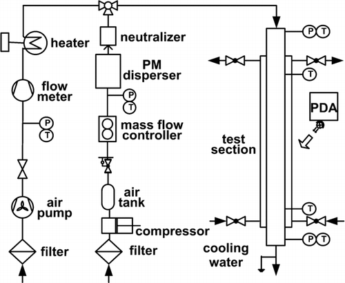
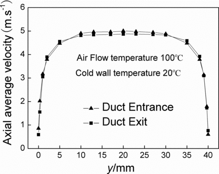
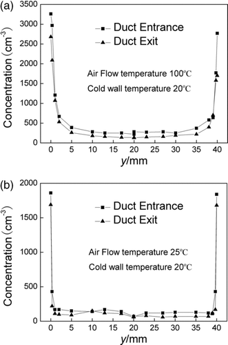
The authors have accomplished the experimental research on the inhalable particles kinematic characteristics and thermophoretic deposition in turbulent air flows. The experimental conditions also become the foundation of numerical simulation. The schematic diagram of the experimental apparatus is shown in . The apparatus essentially consists of a clean air supply system, a particle feed system, an air heater, a test section and a particle measurement and data acquisition system. The clean air driven by an air pump passes through the heater and flows into a particle-intake device. The particles carried by air flow go into a particulate matter disperser (RGB-2000, PALAS GMBH, Germany), then pass through the TSI-3045A Neutralizer (TSI, Germany) where the net charge on the particles is removed and finally are fed into the particle-intake device. In the particle-intake device, the hot air and particles are well mixed then enter the test section. The test section is a vertical rectangular duct made of steel. There are water-jacketed heat exchangers at the test section side walls to establish a temperature gradient between the gas and the water wall. At the test section front wall, there are three optical glass windows arranged at the entrance, middle, and exit of the test section respectively. Through these glass windows, the particles kinematic characteristics and concentration distribution inside the duct were measured by the particle dynamics analyzer (PDA, 58N50, DANTEC, Denmark). The typical experimental results are shown in the Figures and .
3. NUMERICAL SIMULATION
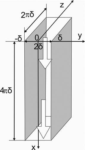
The three-dimensional computational domain modeling the vertical experimental duct is shown in . An incompressible, viscous fluid flows between the two cold walls in the x- direction under a constant pressure gradient. A fully developed laminar velocity profile was used to initialize the flow field with fluctuations added to the x-, y-, and z-velocity components so that the initial flow would approximate fully developed turbulent flow. The computations used a mesh with 64 × 128 ×
64 elements in the x-, y-, and z- directions. The elements were nonuniform in the y- direction and uniform in the x- and z- directions. This arrangement was appropriate to calculate the inhalable particles kinematic characteristics in the near wall region where the thermophoresis effect was dominant. The mesh used in the computational procedure in the x- and y- directions is shown in . The distance between the two flats, parallel walls with a constant temperature of 293 K in the y- direction was 2δ (δ= 0.05 m). At the same time, the x- direction length is 4πδ and z- direction width is 2πδ. The origin of the rectangular coordinate system locates in the middle of the two walls at the channel inlet. In the following data analysis process, the dimensionless coordinates, which are equal to the ratio between the real location coordinates and the half width of the duct (δ), are used to describe the velocity and particle concentration distribution in the y- direction of the duct. It means that the range of y- direction dimensionless coordinates is from –1.0 to 1.0.
The gas flow in the duct is a classical air-particle two-phase flow. The continuity, momentum and energy equations consult the method of CitationYou and Li (2008), shown as:
The particle motion was tracked with the Lagrangian method. The particles were assumed to only be influenced by the drag force and the thermophoretic force. Because the channel is vertical and the focus of this article is the particle deposition near the walls, the gravity was neglected. The equation was shown as follows:
The drag force was calculated as Clift method (Clift et al. 1978).
The thermophoretic force was calculated as reported in the literature (Brock 1967).
After the flow was fully developed, 2.5 μm particles were random added into the flow field at the channel inlet. The initial particle distribution in the flow field was nearly uniform with initial velocities equal to the local fluid velocity. In each time step, firstly calculated the drag force and thermophoretic force value on every single particle to confirm the particle's velocity. Then the velocity should be integrated to gain the particle vector displacement in one time step. During the computation, it was important to consider the particles deposition, impact and agglomeration. If a particle deposited on the cold wall, collided other particle and finally agglomerated, or flowed out of the channel, it would be eliminated from the calculation process.
The temperature gradient creates a thermophoretic force that drives the particles to move towards the cold walls then deposit. In addition, Particle collisions occur more frequently as the particle concentration increases. The impact can ulteriorly lead to particles agglomeration. As the particles volumes grow due to agglomeration, they are more easily to be removed by traditional techniques. Consequently, another method to reduce inhalable particle pollution is increasing the inhalable particle aggregation efficiency. For preferably simulating the particle agglomeration, the particles collisions were modeled by the direct simulation Monte-Carlo (DSMC) method (CitationTanaka et al. 1996) and the Dahneke theory (CitationDahneke 1971) was applied to predict the particle agglomerations and deposition.
The DSMC method has already became an efficacious means to simulate particle to particle collisions. During one time step, after gaining particles velocities and kinetic paths from motion equations, whether the particle to particle collision occurred could be examined by means of the Monte-Carlo procedure (CitationTanaka et al. 1991). The collision partner and geometry conditions were also chosen by Monte-Carlo method.
When one particle collided with another, we imported the Dahneke theory to estimate particles agglomeration. Dahneke assumed that when a particle collides with a surface, the particle adhesion depends on the magnitude of the particle's incident normal velocity and the capture limit velocity, V*, which is given by:
ΔE could be calculated from the classical Bradley-Hamaker theory as:
If the relative velocity between two colliding particles was less than V*, it would be recognized that particles coagulate to form a new agglomerate particle. In this study, define the new particle volume equals to the summation volume of two original particles and calculate the new particle velocity according to the law of conservation of momentum. Contrarily, if colliding particles could not aggregate, the particles velocities after colliding would be calculated by the impulsive equations (CitationCrowe et al. 1998).
The Dahneke model can also be used to determine whether a particle deposits on the cold wall by assuming that the duct wall diameter is infinite. With this assumption, Equation (Equation10) can be simplified to:
Similar to the aggregation calculation procedure, If the particle incident normal velocity of the particle colliding with the cold wall was less than V*, it would be recognized that particle had deposited on the wall and be removed from calculation at next time step. Contrarily, if colliding particles could not deposit, the particle velocity after colliding would also be computed by the impulsive equations.
The important parameters used in the simulation are shown in .
TABLE 1 Parameters used in the simulation
4. RESULTS AND DISCUSSION
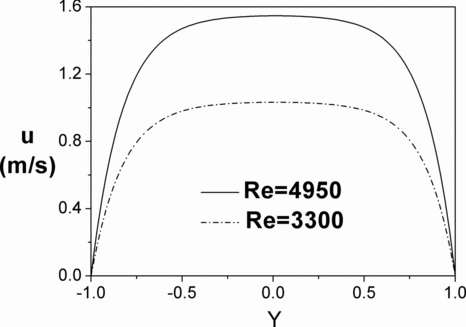
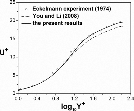
When the entrance air-flow temperature is equal to the cold wall temperature (293 K) and the flow is fully developed, the axial average velocity profiles for different Re numbers in linear dimensionless coordinates are shown in , where the ordinate is the air velocity and the abscissa is the dimensionless distance in the y direction based on the channel half width. , the same velocity profiles on logarithmic coordinates, shows that the recent results agree much better with the classical experimental data (CitationEckelmann 1974) than previous calculations (CitationYou and Li 2008) using a sixth order central difference method to discretize the convection term in the momentum equation. Thus, the present numerical simulations can be utilized to comparatively accurately analyze the turbulent flows. In addition, the upwind scheme is more effective for high Re flows than the central difference method.
When a temperature difference exists in the channel between the fluid and cold walls, the convective heat transfer affects the two-phase flow condition by changing the air properties, such as density and viscosity. Especially in the near wall region where a large temperature gradient exists, the effect of natural convection on the flow which may lead to obvious buoyancy must be considered. The flow can be described by the Oberbeck-Boussinesq model (CitationSanders 1988) which assumes that the fluid has a uniform density and the density differences only influence terms which drive the fluid motion. The density changes are induced by temperature changes but not pressure. The dimensionless momentum equation is:
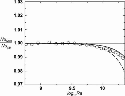
Under the maximum temperature difference (180 K) mentioned in this article, the relevant parameters on natural heat convection could be computed:
According to the Ahlers viewpoint (CitationAhlers et al. 2006), in such a situation, the OB model could be considered to highly approximately simulate the actual heat convection. This conclusion could be proved by . The OB curve (denoted by solid line) is subtotal superposition with NOB curve (denoted by dashed line) and experimental points (denoted by circles) in the range of log10 Ra⩽9.5.
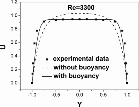
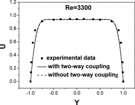
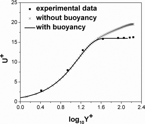
The axial average dimensionless velocity profiles are shown in , for an entrance air temperature of 393 K (maximum temperature difference between the fluid and the cold wall is 100 K) and Re = 3300, including the experimental data and numerical results using two computational methods. shows the same velocity profiles with logarithmic coordinates. The results show that with the buoyancy effect, the predicted profiles agree much better with the experimental data measured at the same temperature and Reynolds number (CitationYang et al. 2008; CitationLiu et al. 2009). Thus, the buoyancy must be considered for more accurately predicting the gas axial velocities.
FIG. 10 Mean velocity profiles normalized by the wall shear velocity with and without buoyancy for Re = 3300.
The particles are random added per time step at the channel entrance after the turbulent flow is fully developed and the particle velocity is equivalent to the local fluid velocity. The particle diameter is 2.5 μm for comparing with the experimental data. To investigate whether the particle phase influences the air phase flow or not, two-way coupling is used to account for the effect of the particles on the structure of the near-wall turbulence and the main stream. The most important factor is the drag force from the particle to the air flow which may influence the air flow. As mentioned above, it could be calculated by Equations (Equation4) and (Equation5).
The axial dimensionless velocity with the two-way coupling affection is shown in for the entrance air temperature of 393 K and Re = 3300. The results show that the 2.5 μm particles do not obviously impact the air phase motion for such flow condition. The axial velocity profiles with or without the two-way coupling are very similar to each other and both agree well with the experimental data.
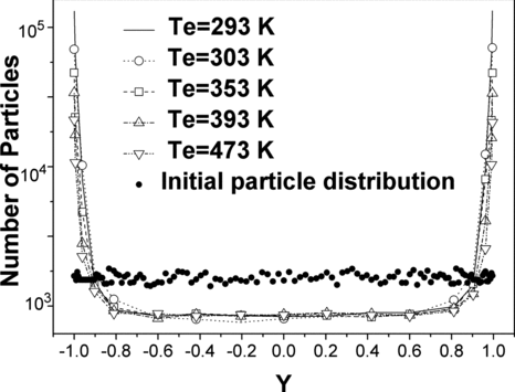
The particle concentration profiles in y- direction for Re = 3300, temperature differences between the entering fluid and the walls are 0 K, 10 K, 60 K, 100 K, and 180 K after 20,000 dimensionless time steps, are shown in the . In these simulation cases, every single time step, one hundred particles were random input into the duct at the inlet. The results indicate that even though the initial particle concentration distributions at the entrance are nearly uniform, the final particle concentration in the near wall area is much higher than that at center region of the channel. One important reason is the turbulent diffusion induces particle enrichment in the boundary layer and lower particle concentrations in the main stream. As shown in , the turbulence vortex which principally consists in the boundary layer and is almost nonexistence in the mainstream area could determine the particles distribution. Some researchers interpreted the turbulent transport on particles by the dimensionless particle relaxation time (CitationDehbi 2008). In this study, the estimate of the dimensionless particle relation time of the 2.5 μm particles is about 0.034 which is similar to the You's simulation condition (CitationYou et al. 2004, CitationYou et al. 2008) and his papers also reported the increased particle concentration close to the wall. Furthermore, comparing to the experimental results in , the particles enrichment is still in existence, even the temperature difference between gas and cold wall is quite small. Nevertheless, the thermophoresis is incontestable another important factor driving particles towards the walls by enhancing the turbulence intensity. The results in show that the predicted particle concentrations at the dimensionless coordinates Y =±1.0 decrease as the temperature increases. The higher temperature difference creates the larger thermophoresis effect which increases the particle deposition. As more particles deposited on the wall, fewer particles exist in the channel, especially in the boundary layer.
FIG. 12 Particle concentration distributions in the y direction for different temperatures and Re = 3300.
To clarify these conclusions, the particle concentration spatial distributions in the near wall region for Y = –0.95 to Y = –1 and Z = 0 to Z = 0.15 in the dimensionless coordinate system were investigated for various values of Re, temperature, initial particle concentration and thermophoretic force. The results in –c indicate that the particle concentration clearly increases from Y = –0.95 to Y = –1. When Re and the initial particle concentration are constant, the entrance temperature difference between the fluid and the walls determines the particles deposition rate and concentration distribution. The increasing entrance temperature difference reduces the number of active particles in the near wall region and more particles deposit on the wall.
FIG. 14 Particle concentration distributions in the near wall region, (a) Re = 3300, Te = 293 K, (b) Re = 3300, Te = 393 K, (c) Re = 3300, Te = 473 K, (d) Re = 3300, Te = 393 K, increased initial particle concentration, (e) Re = 4950, Te = 493 K, (f) Re = 3300, Te = 393 K, without thermophoretic force.
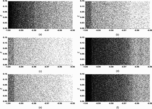
Figures and d show the initial concentration effect on the particle concentration in the near wall region. In the case (d), five hundred particles were random input into the duct at every single time step which is five times of usual case, for example case (b). However, analysis of the statistics shows that the particle deposition efficiency with the significantly high initial particle concentration is just the same level as with lower concentration. Therefore, if the cold wall's particle capture capacity is not saturated, the particle concentration change is not the key parameter affecting the particle deposition efficiency.
Figures and b show effect of Re on the particle deposition. For Re = 4950 situation, the predicted particle concentration and deposition efficiency are both reduced because the higher Reynolds number leads to faster fluid velocities in the mainstream which makes the 2.5 μm particles pass through the channel more quickly. Therefore, the shortened particle residence time limits the particle deposition on the walls.
For a long time, various researchers have focused on analyzing whether thermophoresis or turbulent diffusion affect particle deposition more strongly. The data in show the particle concentrations in the turbulent duct flow with temperature gradient field, when suppose thermophoretic force not to affect particle motion and ignore that during calculation. The simulation results illuminate that compared with predictions in the same turbulence field and the initial particle concentration is also constant, more particles are gathered in the boundary layer, but only minority deposit on the wall. It could be considered that without the thermophoretic force, even a great deal particles transported into the region close to the wall, the majority of the 2.5 μm particles still does not deposit on the cold wall. The thermophoresis is the dominant factor to decide 2.5 μm particles deposition. The hypothesis of this phenomenon could be fairly explained by viscous sub-layer theory. The shows the simulation result of vortex distribution near the cold wall. From this vortex isoline profile, it is indisputability that a laminar sub-layer exists just close to the wall which thickness is about 100 μm. In this sub-layer, the turbulent diffusion and vortex functions which drive particles moving toward the wall almost disappear. It distinctly induces the particle would not deposit on the wall without other forces which have no relationship with turbulence intensity, such as thermophoretic force. With a temperature gradient in the channel radial direction, the thermophoresis pushes the particles towards the low temperature wall, which increases the 2.5 μm particles deposition on the cold wall. Consequently, the turbulent diffusion and vortex could lead to particles enrichment in the near wall area, but the thermophoretic force is the dominant reason to decide particles deposition in temperature gradient field.
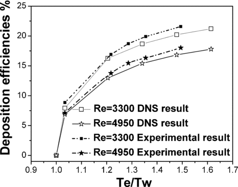
The deposition efficiencies of the 2.5 μm particles were determined from the simulation data in various simulation conditions. The deposition efficiencies are illustrated in , with the abscissa being the ratio of the air temperature at the channel entrance (Te) to the cold wall temperature (Tw). The predictions show that the deposition efficiencies of 2.5 μm particles mainly depend on Te/Tw. The deposition efficiencies increase as temperature ratio increasing when the air flow rate and particle concentration are fixed. When the temperature ratio is one which means that there is no temperature difference between the entrance fluid and the cold wall and the particle deposition is purely turbulent deposition, the turbulent deposition efficiency of only 0.0006% agrees well with the theoretical result (CitationWood 1981). For the conditions in , the deposition rate is only 0.0224%, which is much less than the thermophoretic deposition efficiency at the same temperature ratio and flow situation. Besides temperature, the fluid velocity expressed by the Reynolds number is also an important factor affecting the particles deposition. The increasing Re reduces the particles residence time in the duct due to accelerate the gas flow. Thus, some particles which could have deposited in low velocities would flow out of the duct at high velocities before they had chances to be delivered into the near wall area and removed from the gas. Therefore, the speediness air velocities impede particle to deposit on the duct wall. The predictions are compared with experimental data in to validate the results of the DNS program. The results in show that the simulation results agree reasonably well with the experimental data (CitationYang et al. 2008; CitationLiu et al. 2009).
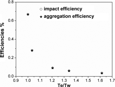
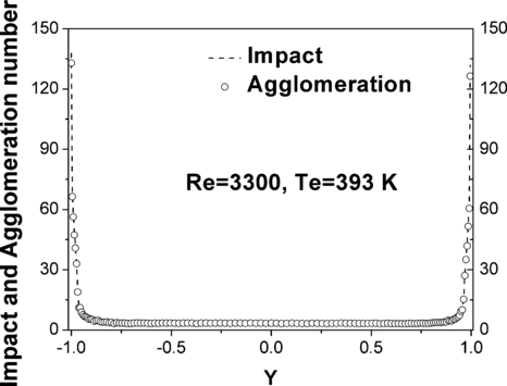
In practical air-particle two-phase flows, the inhalable particles could impact and aggregate more easily by strong thermophoresis and turbulence, particularly in the near wall region with higher particle concentrations. The DSMC method and Dahneke model was used to simulate the particle impact and aggregation process, and the results are given in where the abscissa is the ratio of the air temperature at the channel entrance (Te) to the cold wall temperature (Tw), the ordinate is impact efficiency (the ratio of total particle-collision times to total particle number) and aggregation efficiency (the ratio of total particle-aggregation times to total particle number). Because of the concentration, one important factor is to determine the particle collision and aggregation. When the temperature ratio increases, more particles deposit on the cold wall and at the same time the particle concentration consequentially decrease. So the impact and aggregation efficiencies for the 2.5 μm particles decrease as the temperature ratio increases. The data also shows that 2.5 μm particle colliding usually lead to particle agglomeration. Static analyses show that because of the limited kinetic energy, when these 2.5 μm particles collide, the aggregation probability is over 99%, but the particles tiny volumes limit their colliding chances overly. The typical condition is shown in the . It means that the inhalable particles are difficult to collide; however, once two such particles colliding, they are easy to aggregate. This characteristic of inhalable particles is quite different from large particles with diameters over 10 μm.
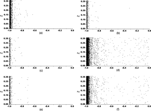
The effect of factors influencing the particle impact and aggregation could be analyzed from . It represents the spatial distribution of particle impact and aggregation in the half channel cross-section from Y = 0 to Y = –1 in the y direction and from Z = 0 to Z = 0.3 in the z direction in the dimensionless coordinate system. The Reynold numbers, the temperatures, the initial particle concentration and the thermophoretic forces are varied in different calculation cases. Few particle aggregations occur in the central part of the channel while many more particles impact and aggregate in the region close to the wall. Comparing to the computation results about particle distribution with the same calculation state, it is specific that the most significant difference between these two areas is the particle concentrations. Accordingly, the simulation results indicate that the particle impact and aggregation is directly proportional to the particle concentration. The areas with more particle collisions and aggregation are the same locations with high particle concentrations.
FIG. 19 Spatial distribution of agglomerates in the half channel region, (a) Re = 3300, Te = 293 K, (b) Re = 3300, Te = 393 K, (c) Re = 3300, Te = 473 K, (d) Re = 3300, Te = 393 K, increased initial particle concentration, (e) Re = 4950, Te = 493 K, (f) Re = 3300, Te = 393 K, without theremophoretic force.
5. CONCLUSIONS
The kinematic characteristics, including the collision, aggregation, and deposition of the inhalable particles in three-dimensional, incompressible turbulent air flows in a channel with temperature gradient are simulated by direct numerical simulations (DNS) method. The high order upwind compact difference schemes to eliminate aliasing error and the Oberbeck-Boussinesq model to consider the influence of natural convection of air on the particle motion are adapted in the numerical calculation to improve the simulation accuracy. The numerical simulation results confirm and extend the experimental investigation on the kinematic characteristics of inhalable particles in the duct. The particle motions including the effects of collisions were calculated using the direct simulation Monte-Carlo (DSMC). The agglomeration and depositions of particles in the turbulent channel flow with a temperature gradient were simulated by the Dahneke model. The research focused on the effects of Re (based on the center velocity and half channel width), the temperature gradient and the particle concentration on particle motion, impact, agglomeration and deposition. The numerical results showed that the thermophoresis dominates the particle deposition, which agrees with the experimental data. The numerical simulation results also show that particle collision and agglomeration are significantly affected by the particle concentration.
This research was supported by the Special Funds for Major State Basic Research Project of China (No. 2002 CB 211604).
REFERENCES
- Ahlers , G. , Broban , E. , Araujo , F. F. , Funfschilling , D. , Grossman , S. and Lohse , D. 2006 . Non-Oberbeck–Boussinesq Effects in Strongly Turbulent Rayleigh-Bernard Convection . J. Fluid. Mech , 569 : 409 – 445 .
- Batchelor , G. K. and Shen , C. 1985 . Thermophoretic Deposition of Particles in Gas Flowing Over Cold Surface . J. Colloid Interface Sci. , 107 ( 1 ) : 21 – 37 .
- Byers , R. L. and Calvert , S. 1969 . Particle Deposition from Turbulent Streams by Means of Thermal Force . I & C. Fundam. , 8 ( 4 ) : 646 – 655 .
- Crowe , C. , Sommerfeld , M. and Tsuji , Y. 1998 . Multiphase Flows with Droplets and Particles , New York : CRC Press .
- Dahneke , B. 1971 . The Capture of Aerosol Particles by Surfaces . J. Colloid interface Sci. , 342 ( 37 )
- Dehbi , A. 2008 . Turbulent Particle Dispersion in Arbitrary Wall-Bounded Geometries: A Coupled CFD Langevin Equation Based Approach . Int. J. Multiphase Flow. , 34 : 819 – 828 .
- Eckelmann , H. 1974 . The Structure of the Viscous Sublayer and the Adjacent Wall Region in a Turbulent Channel Flow . J. Fluid Mech. , 65 : 439 – 472 .
- Housiadas , C. and Drossinos , Y. 2005 . Thermophoretic Deposition in Tube Flow . Aerosol Sci. Technol. , 39 : 304 – 318 .
- Israelachvili , J. N. 1991 . Intermolecular and Surface Forces , 2nd Ed. , London : Academic Press .
- Kim , J. , Moin , P. and Moser , R. D. 1987 . Turbulence Statistics in Fully–Developed Channel Flow at Low Reynolds Number . J. Fluid Mech , 177 : 133 – 166 .
- Liu , R. L. , Yang , R. C. , You , C. F. , Zhao , L. and Zhou , T. 2009 . Kinematic Characteristics and Thermophoretic Deposition of Inhalable Particles in Temperature Gradient Field [In Chinese] . CIESC Journal , 60 ( 7 ) : 1623 – 1628 .
- Messerer , A. , Niessner , R. and Pöschl , U. 2003 . Thermophoretic Deposition of Soot Aerosol Particles Under Experimental Conditions Relevant for Modern Diesel Engine Exhaust Gas Systems . J. Aerosol Sci. , 34 ( 8 ) : 1009 – 1021 .
- Morawska , L. and Zhang , J. 2002 . Combustion Sources of Particles: Health Relevance and Source Signatures . Chemosphere , 49 : 1045 – 1058 .
- Romay , F. J. , Takagaki , S. S. , Pui , D. Y. H. and Liu , B. Y. H. 1998 . Thermophoretic Deposition of Aerosol Particles in Turbulent Tube Flow . J. Aerosol Sci. , 29 ( 8 ) : 943 – 959 .
- Sanders , J. 1988 . Stability of Single-Phase Natural Circulation with Inverted U-Tube Steam Generators . J. Heat Transfer. , 110 : 735 – 742 .
- Talbot , L. , Cheng , R. K. , Schefer , R. W. and Willis , D. R. 1980 . Thermophoresis of Particles in a Heated Boundary Layer . J. Fluid Mech. , 101 : 737 – 758 .
- Tanaka , T. , Kiribayashi , K. and Tsuji , Y. 1991 . “ Monte Carlo Simulation of Gas-Solid Flow in Vertical Pipe or Channel ” . In Proceeding of the International Conference on Multiphase Flows ‘91-Tsuguba , 439 – 442 . Japan : Tsububa .
- Tanaka , T. , Yonemura , S. , Kiribayashi , K. and Tsuji , Y. 1996 . Cluster Formation and Particle Induced Instability in Gas-Solid Flows Predicted by the DSMC Method . JSME. , 39 ( 2 ) : 239 – 245 .
- Wood , N. B. 1981 . The Mass Transfer of Particles and Acid Vapor to Cooled Surfaces . J. Inst. Energy. , 76 : 76 – 93 .
- Yang , R. C. , Liu , R. L. , Zhou , T. and Zhao , L. 2008 . Kinematic Characteristics and Thermophoretic Deposition of Inhalable Particles in Turbulent Duct Flow . Chinese J. Chem. Engin. , 16 ( 2 ) : 192 – 197 .
- You , C. F. , Li , G. H. , Qi , H. Y. and Xu , X. C. 2004 . Motion of Micro–Particles in Channel Flow . Atmos. Environ. , 38 : 1559 – 1565 .
- You , C. F. and Li , G. H. 2008 . Direct Numerical Simulation of Microparticle Motion in Channel Flow with Thermophoresis . J. Environ. Engin. , 134 ( 2 ) : 138 – 144 .
- Zhou , T. , Wang , Z. H. and Yang , R. C. 2005 . Optimization and Improvement of PM2. 5 Thermophoretic Deposition Efficiency in Turbulent Gas Flowing over Tube Surfaces . J. Colloid Interface Sci. , 289 ( 1 ) : 36 – 41 .
